
Lumbar Interbody Fusion Conducted on a Porcine Model with a Bioresorbable Ceramic/Biopolymer Hybrid Implant Enriched with Hyperstable Fibroblast Growth Factor 2

 , , , ,
  , and
, and
Abstract
:1. Introduction
2. Materials and Methods
2.1. Implant Preparation
2.2. Scaffold Morphology
2.3. Mechanical Testing
2.4. In Vitro Testing of Ceramic-Based Scaffolds
2.5. Animal Model and Study Design
2.6. Surgical Method
2.7. General Observation, X-ray Imaging
2.8. X-ray Computed Microtomography (Micro-CT)
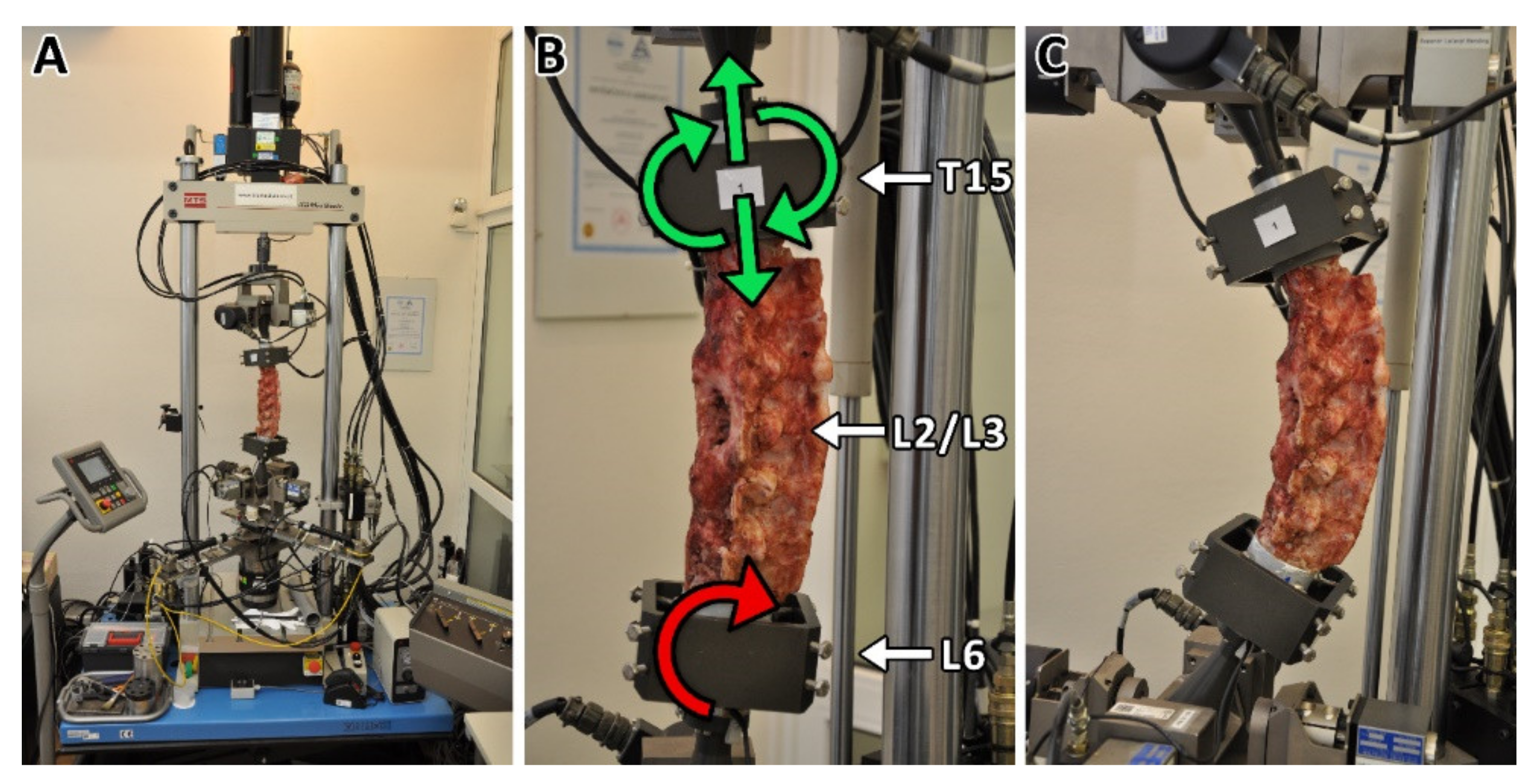
2.9. Biomechanical Testing
2.10. Histological Evaluation
2.11. Statistical Analysis
3. Results
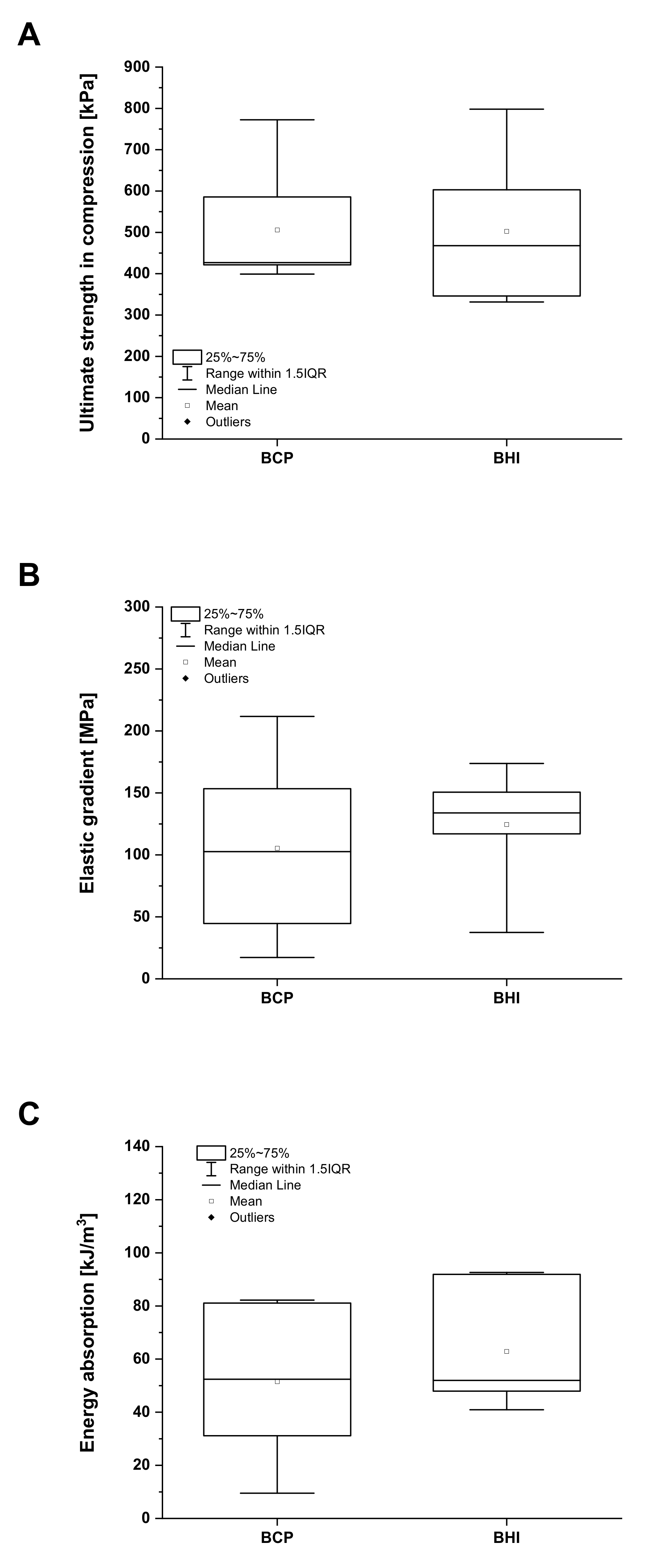
3.1. Bioresorbable Hybrid Implant Properties
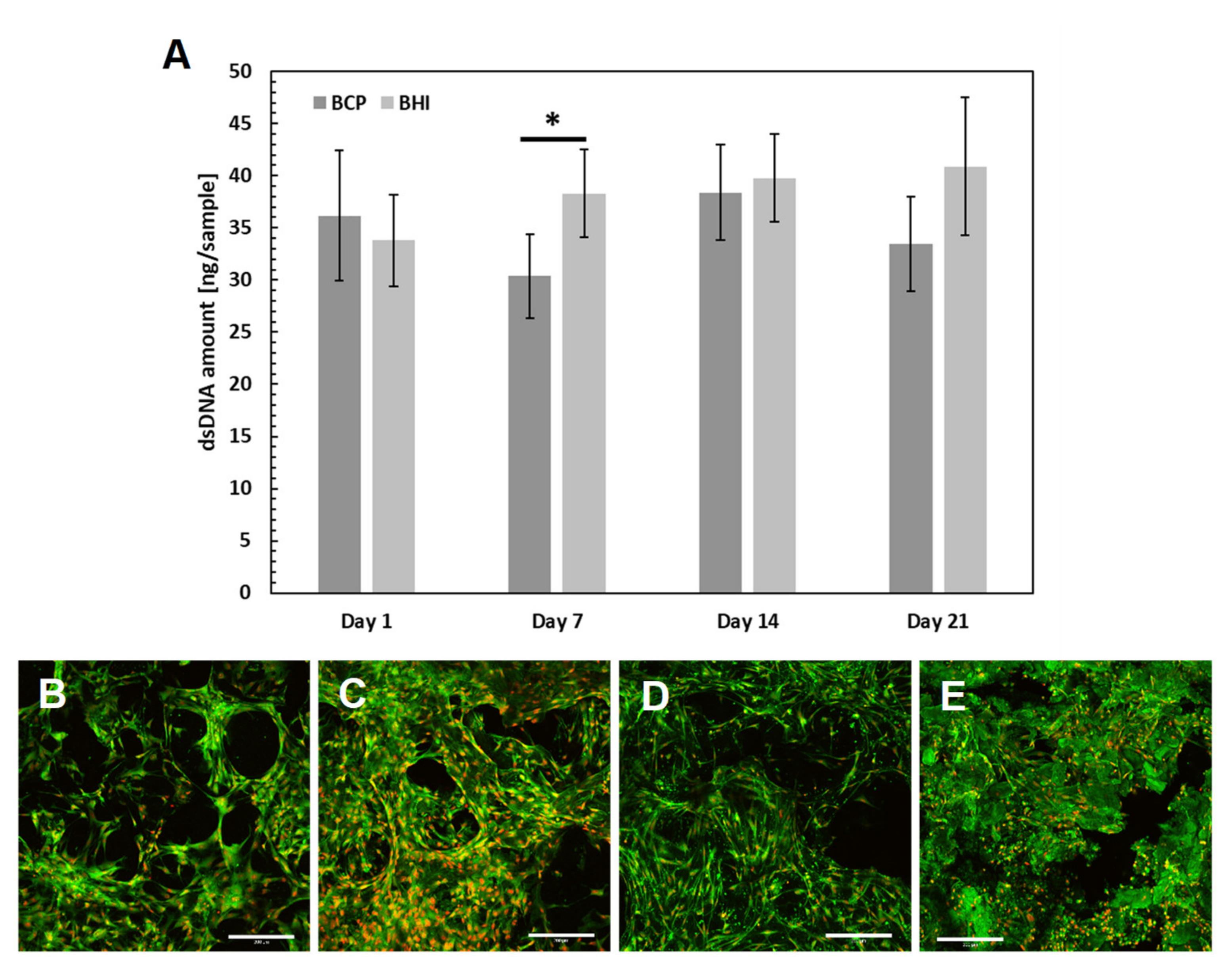
3.2. Cytotoxicity of Prepared Scaffolds
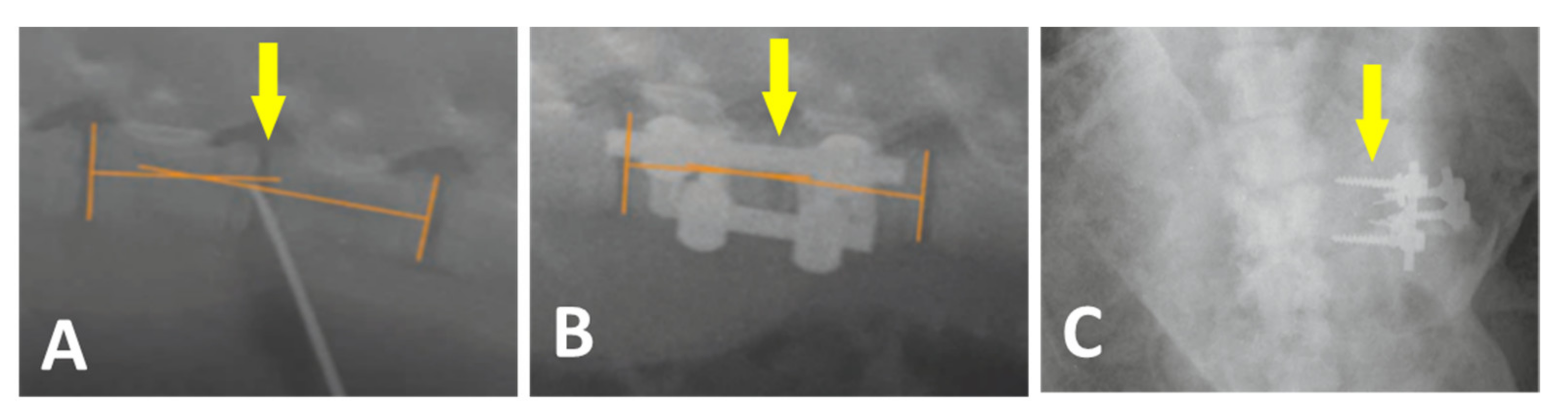
3.3. Surgery
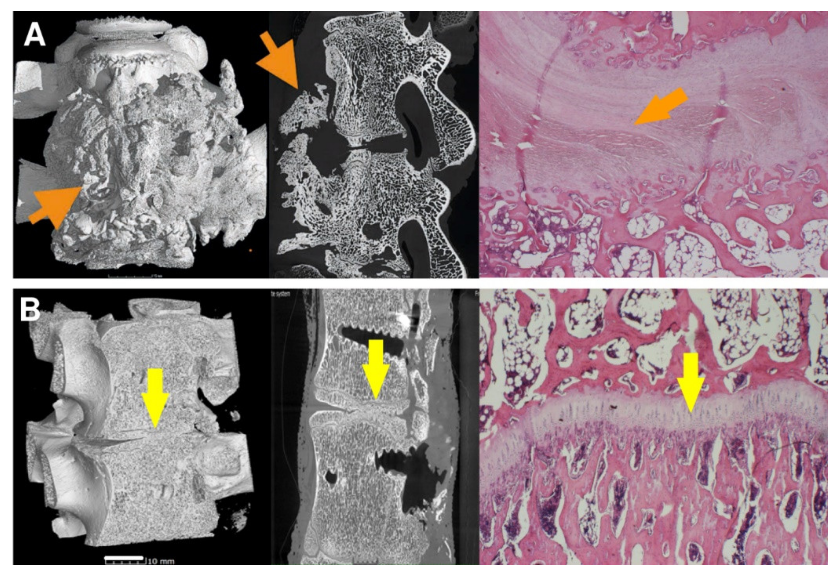
3.4. Micro-CT
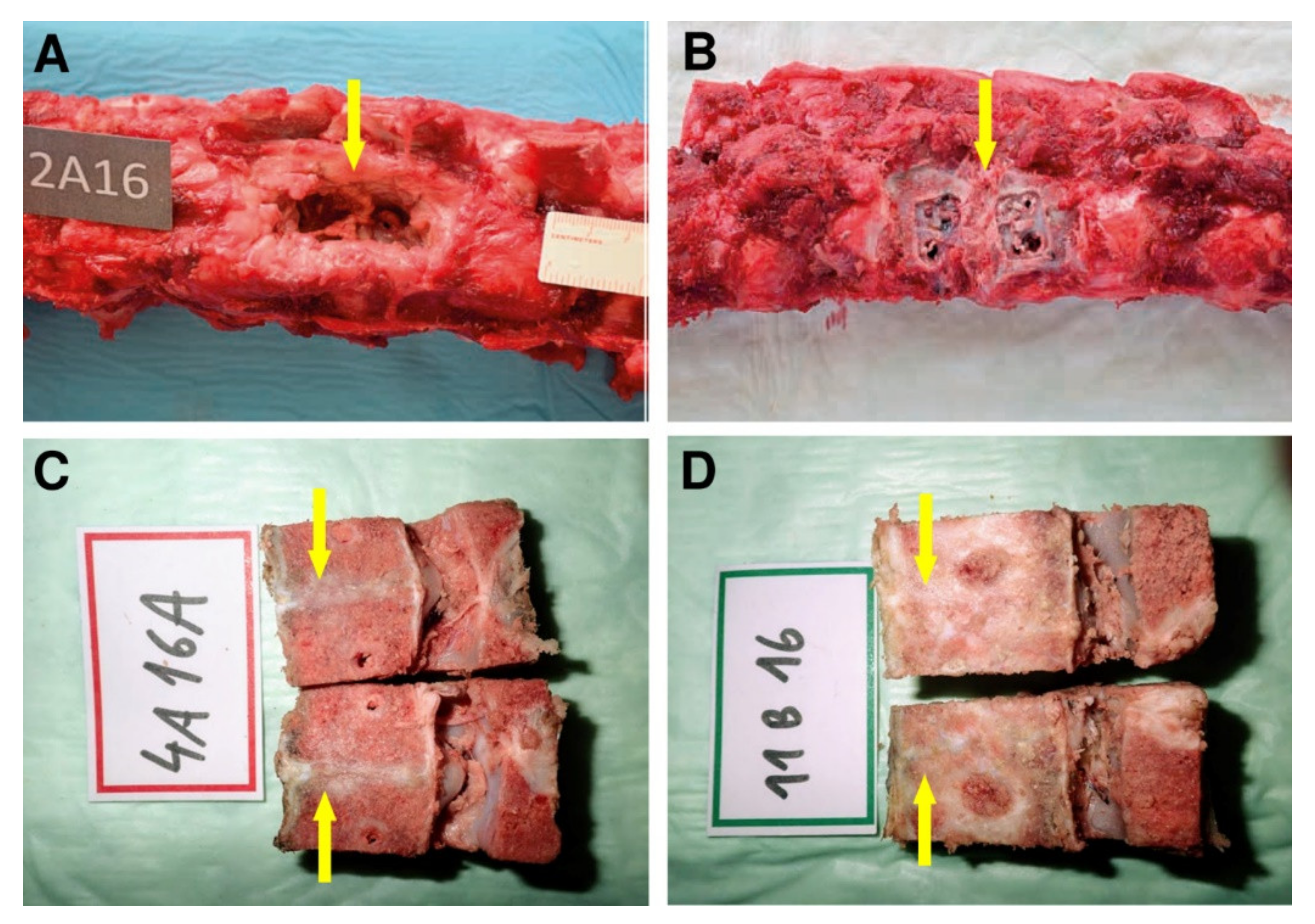
3.5. Histology
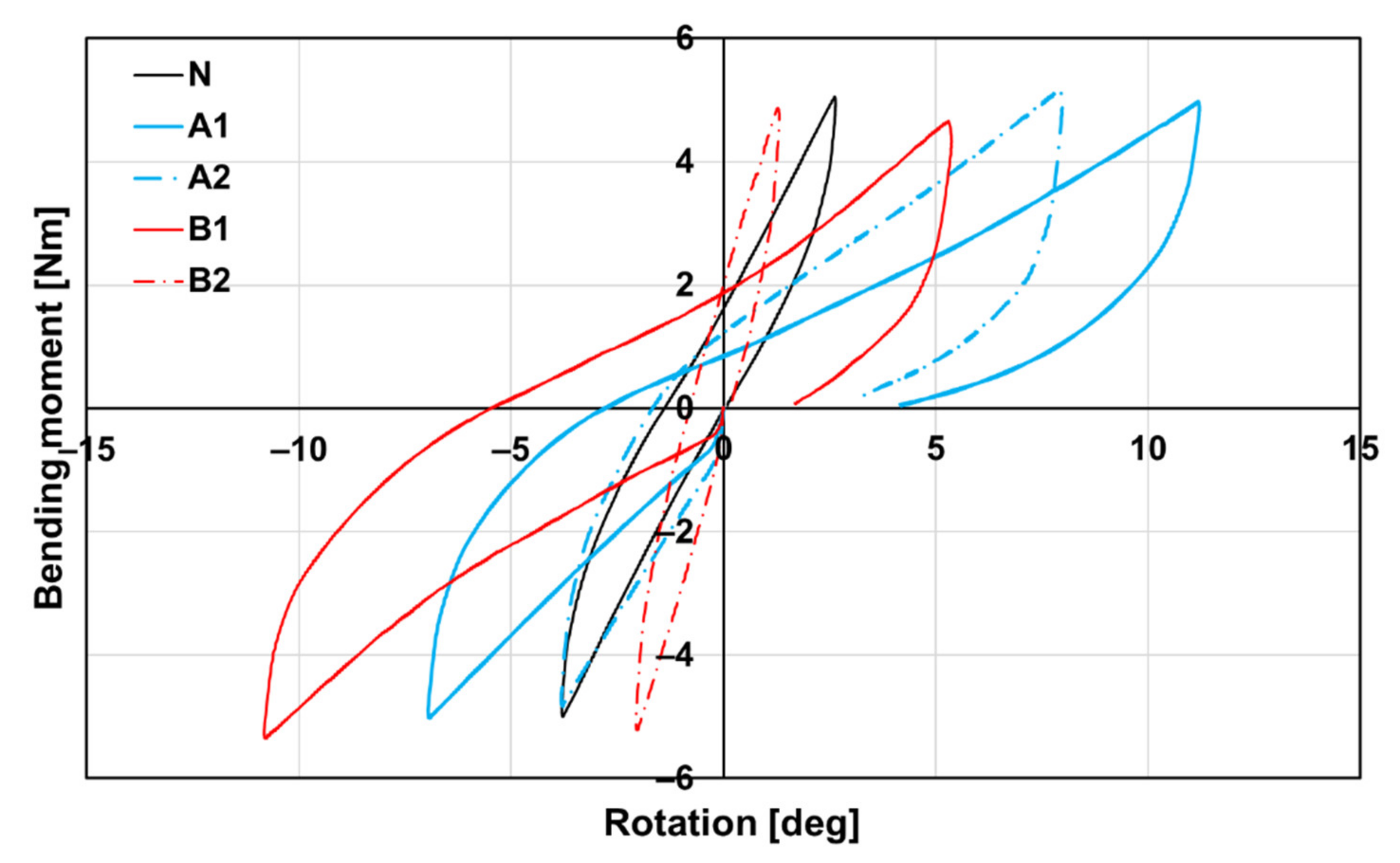
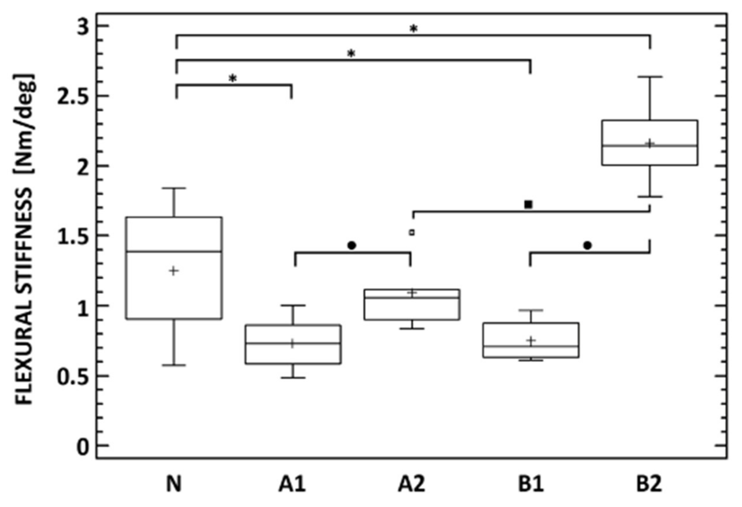
3.6. Biomechanics
4. Discussion
5. Conclusions
Author Contributions
Funding
Institutional Review Board Statement
Informed Consent Statement
Data Availability Statement
Acknowledgments
Conflicts of Interest
References
- Rajaee, S.S.; Bae, H.; Kanim, L.E.; Delamarter, R.B. Spinal fusion in the United States. Spine 2012, 37, 67–76. [Google Scholar] [CrossRef] [Green Version]
- Chun, D.S.; Baker, K.C.; Hsu, W.K. Lumbar pseudarthrosis: A review of current diagnosis and treatment. Neurosurg. Focus 2015, 39, E10. [Google Scholar] [CrossRef] [PubMed] [Green Version]
- Albrektsson, T.; Johansson, C. Osteoinduction, osteoconduction and osseointegration. Use Bone Substit. Spine Surg. 2002, 10, 12–17. [Google Scholar] [CrossRef] [Green Version]
- Seiler, J.G.; Johnson, J. Iliac crest autogenous bone grafting: Donor site complications. J. South. Orthop. Assoc. 2000, 9, 91–97. [Google Scholar] [PubMed]
- Qu, H.; Fu, H.; Han, Z.; Sun, Y. Biomaterials for bone tissue engineering scaffolds: A review. RSC Adv. 2019, 9, 26252–26262. [Google Scholar] [CrossRef] [Green Version]
- Einhorn, T.A. The cell and molecular biology of fracture healing. Clin. Orthop. Relat. Res. 1998, 355S, S7–S21. [Google Scholar] [CrossRef]
- El Bialy, I.; Jiskoot, W.; Nejadnik, M.R. Formulation, Delivery and Stability of Bone Morphogenetic Proteins for Effective Bone Regeneration. Pharm. Res. 2017, 34, 1152–1170. [Google Scholar] [CrossRef] [Green Version]
- Ye, F.; Zeng, Z.; Wang, J.; Liu, H.; Zheng, Z. Comparison of the use of rhBMP-7 versus iliac crest autograft in single-level lumbar fusion: A meta-analysis of randomized controlled trials. J. Bone Miner. Metab. 2017, 350, 119–127. [Google Scholar] [CrossRef]
- Cottrill, E.; Ahmed, A.K.; Lessing, N.; Pennington, Z.; Ishida, W.; Perdomo-Pantoja, A.; Lo, S.-F.; Howell, E.; Holmes, C.; Goodwin, C.R.; et al. Investigational growth factors utilized in animal models of spinal fusion: Systematic review. World J. Orthop. 2019, 10, 176–191. [Google Scholar] [CrossRef]
- Coffin, J.D.; Homer-Bouthiette, C.; Hurley, M.M. Fibroblast Growth Factor 2 and Its Receptors in Bone Biology and Disease. J. Endocr. Soc. 2018, 2, 657–671. [Google Scholar] [CrossRef]
- Inoue, G.; Uchida, K.; Matsushita, O.; Fujimaki, H.; Saito, W.; Miyagi, M.; Sekiguchi, H.; Nishi, N.; Ohtori, S.; Yogoro, M.; et al. Effect of freeze-dried allograft bone with human basic fibroblast growth factor containing a collagen-binding domain from clostridium histolyticum collagenase on bone formation after lumbar poster-olateral fusion surgery in rats. Spine 2017, 42, E995–E1001. [Google Scholar] [CrossRef] [PubMed]
- Charoenlarp, P.; Rajendran, A.K.; Iseki, S. Role of fibroblast growth factors in bone regeneration. Inflamm. Regen. 2017, 37, 1–7. [Google Scholar] [CrossRef] [Green Version]
- Buchtova, M.; Chaloupkova, R.; Zakrzewska, M.; Vesela, I.; Cela, P.; Barathova, J.; Gudernova, I.; Zajickova, R.; Trantirek, L.; Martin, J.; et al. Instability restricts signaling of multiple fibroblast growth factors. Cell. Mol. Life Sci. 2015, 72, 2445–2459. [Google Scholar] [CrossRef]
- Enantis. Stable Fibroblast Growth Factor 2 FGF2-STAB®; Enantis: Brno, Czech Republic, 2017. [Google Scholar]
- Nečas, A.; Proks, P.; Urbanová, L.; Srnec, R.; Stehlík, L.; Crha, M.; Raušer, P.; Plánka, L.; Janovec, J.; Dvořák, M.; et al. Healing of Large Segmental Bone Defect after Implantation of Autogenous Cancellous Bone Graft in Comparison to Hydroxyapatite and 0.5% Collagen Scaffold Combined with Mesenchymal Stem Cells. Acta Veter. Brno 2010, 79, 607–612. [Google Scholar] [CrossRef] [Green Version]
- Prosecka, E.; Rampichova, M.; Vojtová, L.; Tvrdik, D.; Melčáková, Š.; Juhasova, J.; Plencner, M.; Jakubová, R.; Necas, A.; Klepáček, J.; et al. Optimized conditions for mesenchymal stem cells to differentiate into osteoblasts on a collagen/hydroxyapatite matrix. J. Biomed. Mater. Res. Part A 2011, 99, 307–315. [Google Scholar] [CrossRef] [PubMed]
- Plánka, L.; Nečas, A.; Crha, M.; Proks, P.; Vojtova, L.; Gal, P. Treatment of a bone bridge by transplantation of mesenchymal stem cells and chon-drocytes in a composite scaffold in pigs. Experimental study. Acta Chir. Orthop. Traumatol. Cech. 2011, 78, 528–536. [Google Scholar] [PubMed]
- Nečas, A.; Plánka, L.; Srnec, R.; Crha, M.; Hlučilová, J.; Klíma, J.; Starý, D.; Křen, L.; Amler, E.; Vojtova, L.; et al. Quality of newly formed cartilaginous tissue in defects of articular surface after transplantation of mesenchymal stem cells in a composite scaffold based on collagen i with chitosan micro- and nanofibres. Physiol. Res. 2010, 59, 605–614. [Google Scholar] [CrossRef]
- Karageorgiou, V.; Kaplan, D. Porosity of 3D biomaterial scaffolds and osteogenesis. Biomaterials 2005, 26, 5474–5491. [Google Scholar] [CrossRef] [PubMed]
- Wang, M. Composite Scaffolds for Bone Tissue Engineering. Am. J. Biochem. Biotechnol. 2006, 2, 80–84. [Google Scholar] [CrossRef] [Green Version]
- Sukhodub, L.; Moseke, C.; Sulkio-Cleff, B.; Maleev, V.; Semenov, M.; Bereznyak, E.; Bolbukh, T. Collagen–hydroxyapatite–water interactions investigated by XRD, piezogravimetry, infrared and Raman spectroscopy. J. Mol. Struct. 2004, 704, 53–58. [Google Scholar] [CrossRef]
- Sachlos, E.; Gotora, D.; Czernuszka, J.T. Collagen scaffolds reinforced with biomimetic composite nano-sized carbonate-substituted hydroxyapatite crystals and shaped by rapid prototyping to contain internal microchannels. Tissue Eng. 2006, 12, 2479–2487. [Google Scholar] [CrossRef] [PubMed]
- Prosecka, E.; Rampichova, M.; Litvinec, A.; Tonar, Z.; Kralickova, M.; Vojtová, L.; Kochova, P.; Plencner, M.; Buzgo, M.; Mickova, A.; et al. Collagen/hydroxyapatite scaffold enriched with polycaprolactone nanofibers, thrombocyte-rich solution and mesenchymal stem cells promotes regeneration in large bone defect in vivo. J. Biomed. Mater. Res. Part A 2015, 103, 671–682. [Google Scholar] [CrossRef] [PubMed]
- Veillette, C.J.; McKee, M.D. Growth factors—BMPs, DBMs, and buffy coat products: Are there any proven differences amongst them? Injury 2007, 38, S38–S48. [Google Scholar] [CrossRef] [PubMed]
- Babrnáková, J.; Pavliňáková, V.; Brtníková, J.; Sedláček, P.; Prosecká, E.; Rampichová, M.; Filová, E.; Hearnden, V.; Vojtová, L. Synergistic effect of bovine platelet lysate and various polysaccharides on the biological properties of collagen-based scaffolds for tissue engineering: Scaffold preparation, chemo-physical characterization, in vitro and ex ovo evaluation. Mater. Sci. Eng. C 2019, 100, 236–246. [Google Scholar] [CrossRef]
- Ong, S.-Y.; Wu, J.; Moochhala, S.M.; Tan, M.-H.; Lu, J. Development of a chitosan-based wound dressing with improved hemostatic and antimicrobial properties. Biomaterials 2008, 29, 4323–4332. [Google Scholar] [CrossRef]
- Novotna, K.; Havelka, P.; Sopuch, T.; Kolarova, K.; Vosmanska, V.; Lisa, V.; Svorcik, V.; Bacakova, L. Cellulose-based materials as scaffolds for tissue engineering. Cellulose 2013, 20, 2263–2278. [Google Scholar] [CrossRef] [Green Version]
- Hosoya, T.; Bacher, M.; Potthast, A.; Elder, T.; Rosenau, T. Insights into degradation pathways of oxidized anhydroglucose units in cellulose by β-alkoxy-elimination: A combined theoretical and experimental approach. Cellulose 2018, 25, 3797–3814. [Google Scholar] [CrossRef] [Green Version]
- Vojtová, L.; Pavliňáková, V.; Muchová, J.; Kacvinská, K.; Brtníková, J.; Knoz, M.; Lipový, B.; Faldyna, M.; Göpfert, E.; Holoubek, J.; et al. Healing and Angiogenic Properties of Collagen/Chitosan Scaffolds Enriched with Hyperstable FGF2-STAB® Protein: In Vitro, Ex Ovo and In Vivo Comprehensive Evaluation. Biomedicines 2021, 9, 590. [Google Scholar] [CrossRef]
- Muchová, J.; Hearnden, V.; Michlovská, L.; Vištejnová, L.; Zavaďáková, A.; Šmerková, K.; Kočiová, S.; Adam, V.; Kopel, P.; Vojtová, L. Mutual influence of selenium nanoparticles and FGF2-STAB® on biocompatible properties of collagen/chitosan 3D scaffolds: In vitro and ex ovo evaluation. J. Nanobiotechnology 2021, 19, 1–16. [Google Scholar] [CrossRef]
- Dong, C.; Lv, Y. Application of collagen scaffold in tissue engineering: Recent advances and new perspectives. Polymer 2016, 8, 42. [Google Scholar] [CrossRef] [Green Version]
- Šťastný, P.; Sedlacek, R.; Suchý, T.; Lukasova, V.; Rampichova, M.; Trunec, M. Structure degradation and strength changes of sintered calcium phosphate bone scaffolds with different phase structures during simulated biodegradation in vitro. Mater. Sci. Eng. C 2019, 100, 544–553. [Google Scholar] [CrossRef] [PubMed]
- Šťastný, P.; Chlup, Z.; Kalasova, D.; Zikmund, T.; Kaiser, J.; Trunec, M. Epoxy-based gelcasting of machinable hydroxyapatite foams for medical applications. J. Am. Ceram. Soc. 2018, 101, 3317–3327. [Google Scholar] [CrossRef]
- Sloviková, A.; Vojtová, L.; Jančař, J. Preparation and modification of collagen-based porous scaffold for tissue engineering. Chem. Pap. 2008, 62, 417–422. [Google Scholar] [CrossRef]
- Dvorak, P.; Bednar, D.; Vanacek, P.; Balek, L.; Eiselleova, L.; Stepankova, V.; Sebestova, E.; Bosakova, M.; Konecna, Z.; Mazurenko, S.; et al. Computer-assisted engineering of hyperstable fibroblast growth factor 2. Biotechnol. Bioeng. 2018, 115, 850–862. [Google Scholar] [CrossRef] [PubMed]
- Schneider, C.A.; Rasband, W.S.; Eliceiri, K.W. NIH Image to ImageJ: 25 years of image analysis. Nat. Methods 2012, 9, 671–675. [Google Scholar] [CrossRef]
- Tan, G.H.; Goss, B.; Thorpe, P.J.; Williams, R.P. CT-based classification of long spinal allograft fusion. Eur. Spine J. 2007, 16, 1875–1881. [Google Scholar] [CrossRef] [Green Version]
- Scholz, M.; Schleicher, P.; Eindorf, T.; Friedersdorff, F.; Gelinsky, M.; König, U.; Sewing, A.; Haas, N.; Kandziora, F. Cages augmented with mineralized collagen and platelet-rich plasma as an osteoconductive/inductive combination for interbody fusion. Spine 2010, 35, 740–746. [Google Scholar] [CrossRef]
- Chen, G.; Gulbranson, D.R.; Yu, P.; Hou, Z.; Thomson, J.A. Thermal stability of fibroblast growth factor protein is a determinant factor in regulating self-renewal, differentiation, and reprogramming in human pluripotent stem cells. Stem Cells 2011, 30, 623–630. [Google Scholar] [CrossRef] [PubMed] [Green Version]
- Andreopoulos, F.M.; Persaud, I. Delivery of basic fibroblast growth factor (bFGF) from photoresponsive hydrogel scaffolds. Biomaterials 2006, 27, 2468–2476. [Google Scholar] [CrossRef] [PubMed]
- Cai, S.; Liu, Y.; Shu, X.Z.; Prestwich, G.D. Injectable glycosaminoglycan hydrogels for controlled release of human basic fibroblast growth factor. Biomaterials 2005, 26, 6054–6067. [Google Scholar] [CrossRef]
- Benington, L.; Rajan, G.; Locher, C.; Lim, L.Y. Fibroblast Growth Factor 2—A Review of Stabilisation Approaches for Clinical Applications. Pharmaceutics 2020, 12, 508. [Google Scholar] [CrossRef] [PubMed]
- Koledova, Z.; Sumbal, J.; Rabata, A.; De La Bourdonnaye, G.; Chaloupkova, R.; Hrdlickova, B.; Damborsky, J.; Stepankova, V. Fibroblast growth factor 2 protein stability provides decreased dependence on heparin for induction of FGFR signaling and alters ERK signaling dynamics. Front. Cell Dev. Biol. 2019, 7, 331. [Google Scholar] [CrossRef] [Green Version]
- Kanematsu, A.; Marui, A.; Yamamoto, S.; Ozeki, M.; Hirano, Y.; Yamamoto, M.; Ogawa, O.; Komeda, M.; Tabata, Y. Type I collagen can function as a reservoir of basic fibroblast growth factor. J. Control. Release 2004, 99, 281–292. [Google Scholar] [CrossRef] [PubMed]
- Munisso, M.C.; Morimoto, N.; Notodihardjo, S.C.; Mitsui, T.; Kakudo, N.; Kusumoto, K. Collagen/Gelatin Sponges (CGSs) Provide Both Protection and Release of bFGF: An In Vitro Study. BioMed Res. Int. 2019, 2019, 1–9. [Google Scholar] [CrossRef] [PubMed] [Green Version]
- Wu, J.M.; Xu, Y.Y.; Li, Z.H.; Yuan, X.Y.; Wang, P.F.; Zhang, X.Z.; Liu, Y.Q.; Guan, J.; Guo, Y.; Li, R.X.; et al. Heparin-functionalized collagen matrices with controlled release of basic fibroblast growth factor. J. Mater. Sci. Mater. Med. 2011, 22, 107–114. [Google Scholar] [CrossRef]
- Ludwig, T.E.; Levenstein, M.E.; Jones, J.M.; Berggren, W.T.; Mitchen, E.R.; Frane, J.L.; Crandall, L.J.; A Daigh, C.; Conard, K.R.; Piekarczyk, M.S.; et al. Derivation of human embryonic stem cells in defined conditions. Nat. Biotechnol. 2006, 24, 185–187. [Google Scholar] [CrossRef]
- Oh, S.H.; Park, I.K.; Kim, J.M.; Lee, J.H. In vitro and in vivo characteristics of PCL scaffolds with pore size gradient fabricated by a centrifugation method. Biomaterials 2007, 28, 1664–1671. [Google Scholar] [CrossRef]
- Marie, P. Fibroblast growth factor signaling controlling osteoblast differentiation. Gene 2003, 316, 23–32. [Google Scholar] [CrossRef]
- Suchý, T.; Šupová, M.; Bartoš, M.; Sedláček, R.; Piola, M.; Soncini, M.; Fiore, G.B.; Sauerova, P.; Kalbacova, M.H. Dry versus hydrated collagen scaffolds: Are dry states representative of hydrated states? J. Mater. Sci. Mater. Med. 2018, 29, 20. [Google Scholar] [CrossRef]
- Mosekilde, L.; Mosekilde, L. Normal vertebral body size and compressive strength: Relations to age and to vertebral and iliac trabecular bone compressive strength. Bone 1986, 7, 207–212. [Google Scholar] [CrossRef]
- De Faria, S.P. Biomechanical Analysis of the Human Lumbar Spine—An Experimental and Computational Approach; LAETA, IDMEC, IST: Lisbon, Portugal, 2015. [Google Scholar]
- Busscher, I.; van der Veen, A.J.; van Dieën, J.H.; Kingma, I.; Verkerke, G.J.; Veldhuizen, A.G. In vitro biomechanical characteristics of the spine. Spine 2010, 35, E35–E42. [Google Scholar] [CrossRef] [PubMed]
- Lee, J.H.; Nam, Y.; Lee, J.-H. Animal models of orthopedic research: A spinal fusion model. J. Korean Orthop. Assoc. 2017, 52, 344–349. [Google Scholar] [CrossRef]
- McGilvray, K.C.; Waldorff, E.I.; Easley, J.; Seim, H.B.; Zhang, N.; Linovitz, R.J.; Ryaby, J.T.; Puttlitz, C.M. Evaluation of a polyetheretherketone (PEEK) titanium composite interbody spacer in an ovine lumbar interbody fusion model: Biomechanical, microcomputed tomographic, and histologic analyses. Spine J. 2017, 17, 1907–1916. [Google Scholar] [CrossRef] [Green Version]
- Yong, M.R.; Saifzadeh, S.; Askin, G.N.; Labrom, R.D.; Hutmacher, D.W.; Adam, C.J. Biological performance of a polycaprolactone-based scaffold plus recombinant human morphogenetic protein-2 (rhBMP-2) in an ovine thoracic interbody fusion model. Eur. Spine J. 2013, 23, 650–657. [Google Scholar] [CrossRef] [PubMed] [Green Version]
- Chau, A.M.T.; Xu, L.L.; Wong, J.H.-Y.; Mobbs, R.J. Current status of bone graft options for anterior interbody fusion of the cervical and lumbar spine. Neurosurg. Rev. 2013, 37, 23–37. [Google Scholar] [CrossRef]
- Sherman, B.P.; Lindley, E.M.; Turner, A.S.; Iii, H.B.S.; Benedict, J.; Burger, E.L.; Patel, V.V. Evaluation of ABM/P-15 versus autogenous bone in an ovine lumbar interbody fusion model. Eur. Spine J. 2010, 19, 2156–2163. [Google Scholar] [CrossRef] [PubMed] [Green Version]
- Ren, C.; Song, Y.; Xue, Y.; Yang, X.; Zhou, C. Evaluation of bioabsorbable multiamino acid copolymer/nanohydroxyapatite/calcium sulfate cage in a goat spine model. World Neurosurg. 2017, 103, 341–347. [Google Scholar] [CrossRef]
- Xu, H.; Zhang, F.; Wang, H.; Geng, F.; Shao, M.; Xu, S.; Xia, X.; Ma, X.; Lu, F.; Jiang, J. Evaluation of a Porous Bioabsorbable Interbody Mg-Zn Alloy Cage in a Goat Cervical Spine Model. BioMed Res. Int. 2018, 2018, 1–10. [Google Scholar] [CrossRef] [Green Version]
- Abbah, S.A.; Lam, C.X.; Ramruttun, K.A.; Goh, J.C.; Wong, H.-K. Autogenous bone marrow stromal cell sheets-loaded mpcl/tcp scaffolds induced osteogenesis in a porcine model of spinal interbody fusion. Tissue Eng. Part A 2011, 17, 809–817. [Google Scholar] [CrossRef]
- Dewan, A.K.; Dewan, R.A.; Calderon, N.; Fuentes, A.; Lazard, Z.; Davis, A.R.; Heggeness, M.; Hipp, J.A.; Olmsted-Davis, E.A. Assessing mechanical integrity of spinal fusion by in situ endochondral oste-oinduction in the murine model. J. Orthop. Surg. Res. 2010, 5, E1–E9. [Google Scholar] [CrossRef] [Green Version]
- Kroeze, R.J.; Smit, T.H.; Vergroesen, P.-P.; Bank, R.A.; Stoop, R.; Van Rietbergen, B.; Van Royen, B.J.; Helder, M.N. Spinal fusion using adipose stem cells seeded on a radiolucent cage filler: A feasibility study of a single surgical procedure in goats. Eur. Spine J. 2014, 24, 1031–1042. [Google Scholar] [CrossRef] [PubMed]
- Daentzer, D.; Willbold, E.; Kalla, K.; Bartsch, I.; Masalha, W.; Hallbaum, M.; Hurschler, C.; Kauth, T.; Kaltbeitzel, D.; Hopmann, C.; et al. Bioabsorbable interbody magnesium-polymer cage. Spine 2014, 39, E1220–E1227. [Google Scholar] [CrossRef] [PubMed]
- Tang, J.; Guo, J.; Li, Z.; Yang, C.; Xie, D.; Chen, J.; Li, S.; Li, S.; Kim, G.B.; Bai, X.; et al. A fast degradable citrate-based bone scaffold promotes spinal fusion. J. Mater. Chem. B 2015, 3, 5569–5576. [Google Scholar] [CrossRef] [Green Version]
- Abbah, S.A.; Lam, C.X.; Ramruttun, A.K.; Goh, J.C.; Wong, H.-K. Fusion performance of low-dose recombinant human bone morphogenetic protein 2 and bone marrow-derived multipotent stromal cells in biodegradable scaffolds. Spine 2011, 36, 1752–1759. [Google Scholar] [CrossRef] [PubMed]
- Sandhu, H.S.; Toth, J.M.; Diwan, A.; Seim, H.B.; Kanim, L.E.; Kabo, J.M.; Turner, A.S. Histologic evaluation of the efficacy of rhbmp-2 compared with autograft bone in sheep spinal anterior interbody fusion. Spine 2002, 27, 567–575. [Google Scholar] [CrossRef] [PubMed] [Green Version]
- Manzur, M.; Virk, S.S.; Jivanelli, B.; Vaishnav, A.S.; McAnany, S.J.; Albert, T.J.; Iyer, S.; Gang, C.H.; Qureshi, S. The rate of fusion for stand-alone anterior lumbar interbody fusion: A systematic review. Spine J. 2019, 19, 1294–1301. [Google Scholar] [CrossRef]


| 8 Weeks | 16 Weeks | |||||
|---|---|---|---|---|---|---|
| Fusion Grade | Subgroup A1 (n = 6) Autograft | Subgroup B1 (n = 6) BHI | p | Subgroup A2 (n = 6) Autograft | Subgroup B2 (n = 6) BHI | p |
| I | 3 | 2 | 1 | 5 | ||
| II | 1 | 2 | 0.737 | 3 | 1 | 0.023 * |
| III | 1 | 1 | 2 | 0 | ||
| IV | 1 | 1 | 0 | 0 | ||
Publisher’s Note: MDPI stays neutral with regard to jurisdictional claims in published maps and institutional affiliations. |
© 2021 by the authors. Licensee MDPI, Basel, Switzerland. This article is an open access article distributed under the terms and conditions of the Creative Commons Attribution (CC BY) license (https://creativecommons.org/licenses/by/4.0/).
Share and Cite
Krticka, M.; Planka, L.; Vojtova, L.; Nekuda, V.; Stastny, P.; Sedlacek, R.; Brinek, A.; Kavkova, M.; Gopfert, E.; Hedvicakova, V.; et al. Lumbar Interbody Fusion Conducted on a Porcine Model with a Bioresorbable Ceramic/Biopolymer Hybrid Implant Enriched with Hyperstable Fibroblast Growth Factor 2. Biomedicines 2021, 9, 733. https://doi.org/10.3390/biomedicines9070733
Krticka M, Planka L, Vojtova L, Nekuda V, Stastny P, Sedlacek R, Brinek A, Kavkova M, Gopfert E, Hedvicakova V, et al. Lumbar Interbody Fusion Conducted on a Porcine Model with a Bioresorbable Ceramic/Biopolymer Hybrid Implant Enriched with Hyperstable Fibroblast Growth Factor 2. Biomedicines. 2021; 9(7):733. https://doi.org/10.3390/biomedicines9070733
Chicago/Turabian StyleKrticka, Milan, Ladislav Planka, Lucy Vojtova, Vladimir Nekuda, Premysl Stastny, Radek Sedlacek, Adam Brinek, Michaela Kavkova, Eduard Gopfert, Vera Hedvicakova, and et al. 2021. "Lumbar Interbody Fusion Conducted on a Porcine Model with a Bioresorbable Ceramic/Biopolymer Hybrid Implant Enriched with Hyperstable Fibroblast Growth Factor 2" Biomedicines 9, no. 7: 733. https://doi.org/10.3390/biomedicines9070733