YAG Laser Rod 3D Corrective Process Optimization through Tool Influent Function Shape Inspection

1
TOPTEC, Institute of Plasma Physics, Academy of Sciences of the Czech Republic, Turnov, 1660, 51101 Sobotecka, Czech Republic
2
CRYTUR, spol. s r.o., Turnov, 2283, 51101 Na Lukách, Czech Republic
*
Author to whom correspondence should be addressed.
Appl. Sci. 2020, 10(22), 8194; https://doi.org/10.3390/app10228194
Submission received: 5 October 2020
/
Revised: 7 November 2020
/
Accepted: 17 November 2020
/
Published: 19 November 2020
Abstract
:Featured Application
3D subaperture surface shape correction of YAG laser rods for solid-state laser production.
Abstract
Due to the increasing demands on the quality of solid-state laser active media production based on yttrium aluminum garnet Y3Al5O12 in the form of rods with precisely machined faces, the possibilities of applying subaperture 3D corrective polishing in this segment of optical production were studied. For the considered laser rod diameters of up to 10 mm, the corrective process had to be optimized to achieve a stable, suitably shaped tool influence function at the full width at half maximum of approximately 1.5 mm, enabling 3D shape corrections with sufficient lateral resolution. For this purpose, a number of experiments were performed using both tools based on a flexible elastic membrane inflated by compressed air and tools with a viscoelastic head, and the effect of the tool-polished surface interaction was studied and analyzed.
1. Introduction
Yttrium aluminum garnet Y3Al5O12 (YAG) is an optically isotropic crystal of cubic structure characterized by a high Mohs hardness of 8.5 and a relatively high thermal conductivity of approximately 13 W/mK. The crystals are grown by the Czochralski method by drawing an oriented crystal nucleus from a melt placed in an iridium or molybdenum crucible. Neodymium ion-doped YAG is the most widespread active medium in the field of solid-state laser application, where it is used in the form of rods with precisely machined (polished) faces with high demands on both minimum surface micro-roughness and shape error, which can be further minimized by 3D subaperture shape correction.
However, in the process of 3D shape correction of optical surfaces by computer numerical control (CNC) technologies, where the subaperture tool moves along precisely defined paths, specific structures are generated, often falling into the category of so-called mid-spatial frequencies (MSFs) [1], which can significantly limit the optical properties of the resulting optical element. The causes of MSF generation are numerous [2] and include the geometry and material properties of the polishing tool. The resulting character of the surface is then determined by their interaction. In addition, the precision of 3D shape correction controlled by dwell time algorithms [3,4] is significantly affected by the possibility of achieving the most accurate tool influence function (TIF) shape modeling using a suitable mathematical approach. A rotationally symmetric Gaussian function [5] is often used, which, in many cases, may not be accurate enough and thus may introduce a substantial systematic error into the process of 3D correction. The polishing tool geometry, its construction material, and the process settings used all have a significant effect on both the final surface quality and the final shape accuracy; therefore, their optimization must be given considerable attention.
Besides non-contact shape correction methods such as ion beam figuring (IBF) [6] or fluid jet polishing (FJP) [7], the dominant method for dwell time shape correction consists of processes based on contact tool utilization, where the active tool part consists of a flexible elastic membrane (FEM) inflated by compressed air or of a viscoelastic head (VEH) [8]. The contact between the tool and the polished (corrected) surface is then realized by a suitably selected polishing pad. Material removal can generally be described using the traditional Preston relation (1):
where k is the process parameter, p is the pressure on the polished surface, v is the relative velocity of the tool-surface movement, and Δt is the dwell time.
Δh(x;y) = k × p(x;y) × v(x;y) × Δt(x;y)
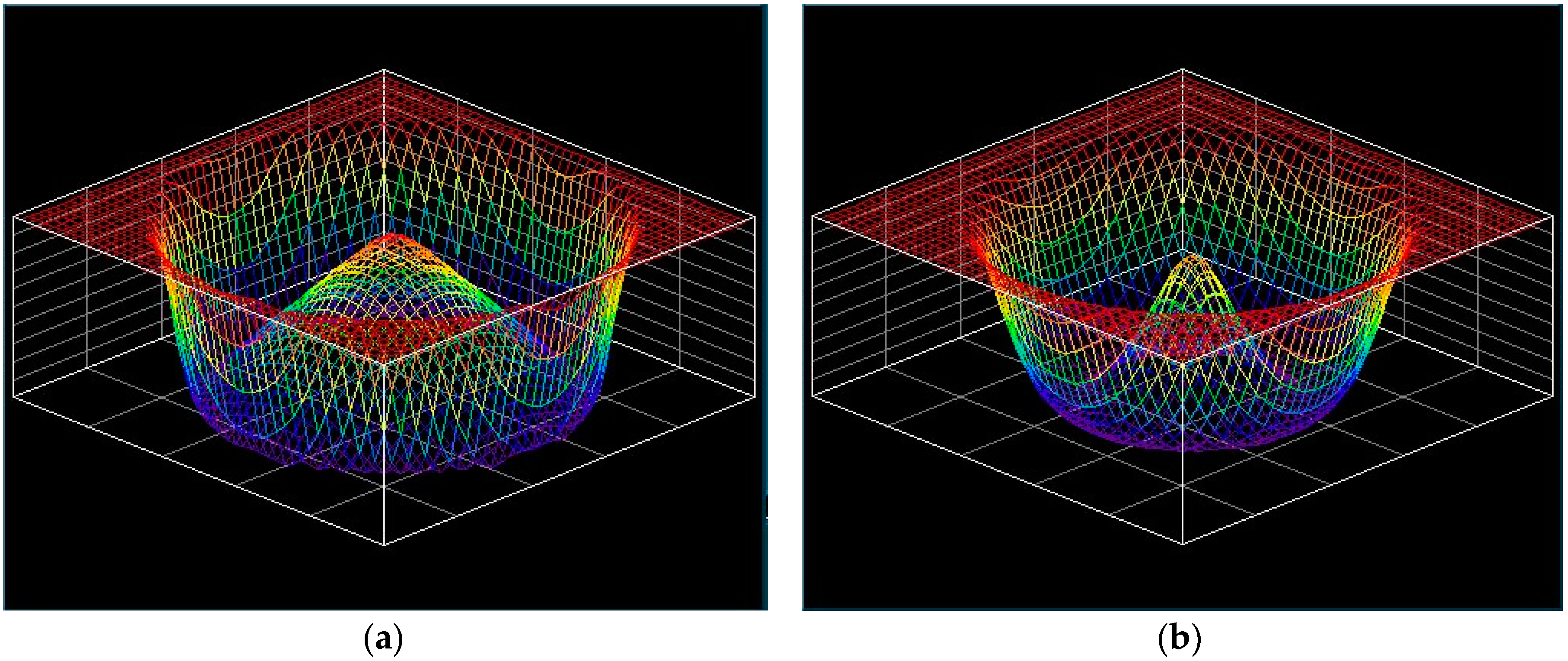
Based on Equation (1), in the case of a static tool action (without movement in the x and y axes), at a selected pressure, tool speed, and at a given dwell time, material removal can be simulated relatively easily (see Figure 1) because pressure is either constant (for the FEM tool) or given by the tool deformation caused by interaction with the workpiece surface [9].
However, the above-presented simulation models assume a relatively simple pressure distribution due to the perfectly elastic behavior of the tool material, which can be described by Hooke’s law (2):
where δ is the stress in the material (δ determines the polishing pressure), ε is the relative deformation, and E is the elastic modulus.
δ = E × ε
Nevertheless, this assumption about tool construction materials based on rubbers or other organic polymers does not correspond with reality [10]; for a description of their behavior (under static stress), it is necessary to use, at minimum, more complex models such as Voight’s model (3):
where η is the viscosity of a considered material and dε/dt is the relative deformation change with time.
δ = E × ε + η × (dε/dt)
The situation is also complicated by the fact that in the process of subaperture polishing, it is dynamic rather than static stress of the polishing tool that occurs, and that the real behavior of commonly used tool construction materials can differ significantly in both of the loading types [11]. In addition to the possible nonlinearity of the elastic modulus and material creep, their dependence on the oscillating deformation frequency may also occur [12]. In this case, it is necessary to use a very complex mathematical apparatus to describe the real pressure distribution in the polishing spot area using a number of viscoelastic material parameters, such as complex modulus of elasticity, storage modulus, and loss modulus, which need to be experimentally determined [13]. This fact significantly limits the possibility of using this approach to optimize the properties of the polishing tool. If we further consider the influence of the uneven polishing slurry distribution caused by the pressure distribution and by the centrifugal effect, the only usable method of tool optimization remains the use of spot experiments.
2. Optimization Experiments
In the process of YAG 3D correction optimization, the aim of this work was to select a suitable constructional and geometric tool—workpiece arrangement, allowing precise control of a spot the size of approximately 1.5 mm and a suitable process setup under which the simplest possible TIF shape could be generated without a significant central artifact and without a significant ripple. This was especially important to ensure precise mathematical fitting, which was necessary to minimize of the residual shape error after 3D dwell time correction as well as the generated MSF. It should be noted that YAG is a very hard crystalline material, whose subaperture 3D correction is time consuming due to very low removal rates, and any deviations between the theoretical correction model and the actual process lead to large residual errors.
The spot experiments were performed on 20 × 60 × 2 mm YAG plates fixed on a HD25 holder. A Zeeko IRP 100 polishing device (for the VEH tool) and an Optotech MCP 250 CNC device (for the FEM tool) were used for testing. In both cases, aqueous suspensions of Cerox were used as the polishing slurry and polyurethane foil as the polishing pad. For the VEH tool experiments, a polyurethane viscoelastic head prepared in Toptec [13] was utilized. The experiment conditions are shown in Table 1. A spot size of approximately 5 mm was chosen to enable a more detailed TIF analysis and for a better mapping of the influence of the participating factors.
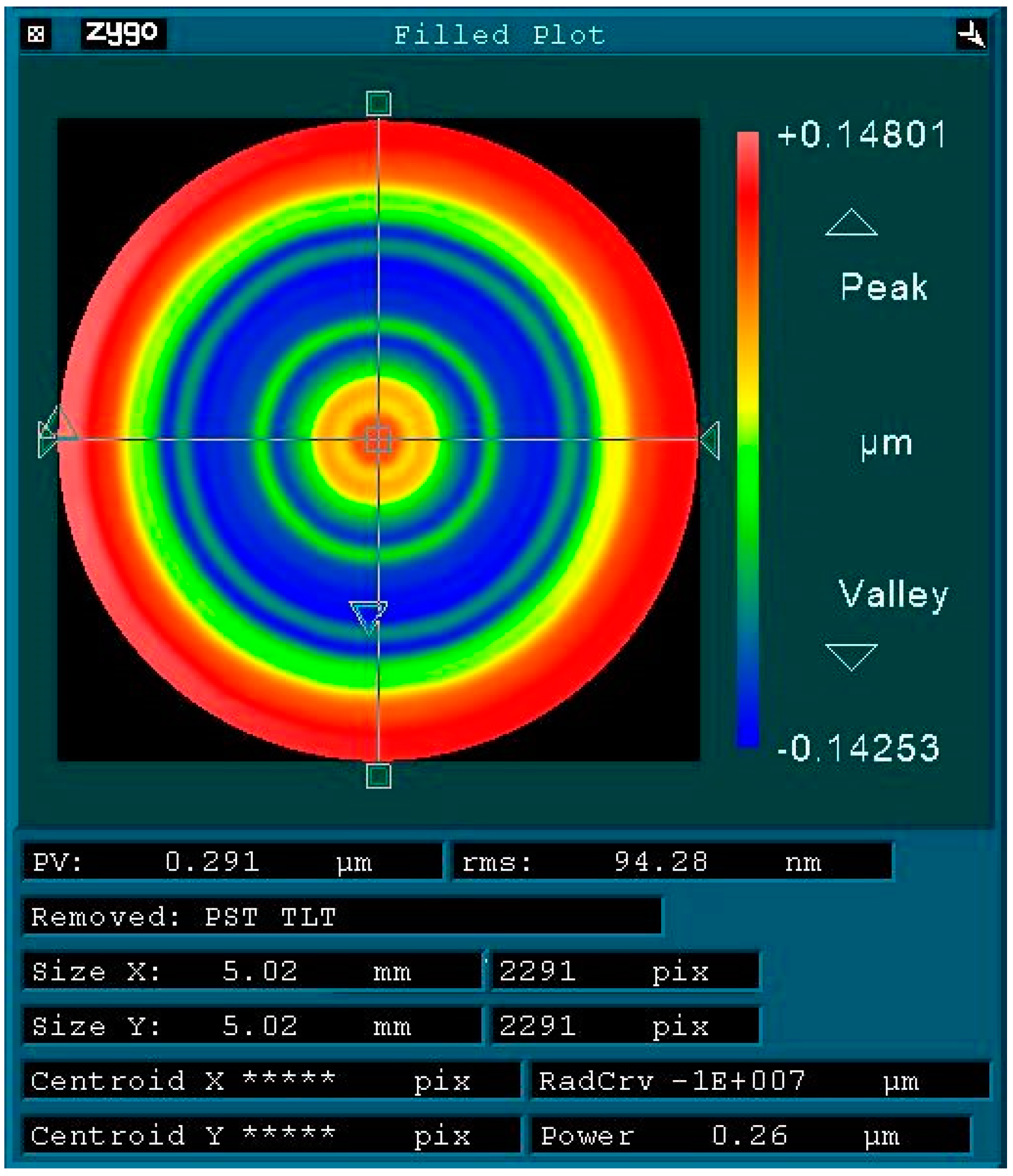
In the spot experiments, the spherical R10 or plane R0 tools with a polishing spot diameter of approximately 5 mm were left in contact with the planar surface of the YAG plate at the defined speed for 30 s and, subsequently, the generated spots were checked by an interferometer. In the next step, white light interferometry (WLI) at a magnification of 5x was used to capture the fine structure of the spots; the spot area was scanned in the 6 × 6 mm stitching mode (Figure 2). Tool speeds of 600, 700, 800, and 900 rpm were tested; in the case of the FEM tool, pressures of 0, 0.7, and 1.5 bar were tested. The obtained results were processed using the Zeeko Metrology Toolkit and the Zygo MetroPro software.
3. Results and Discussion
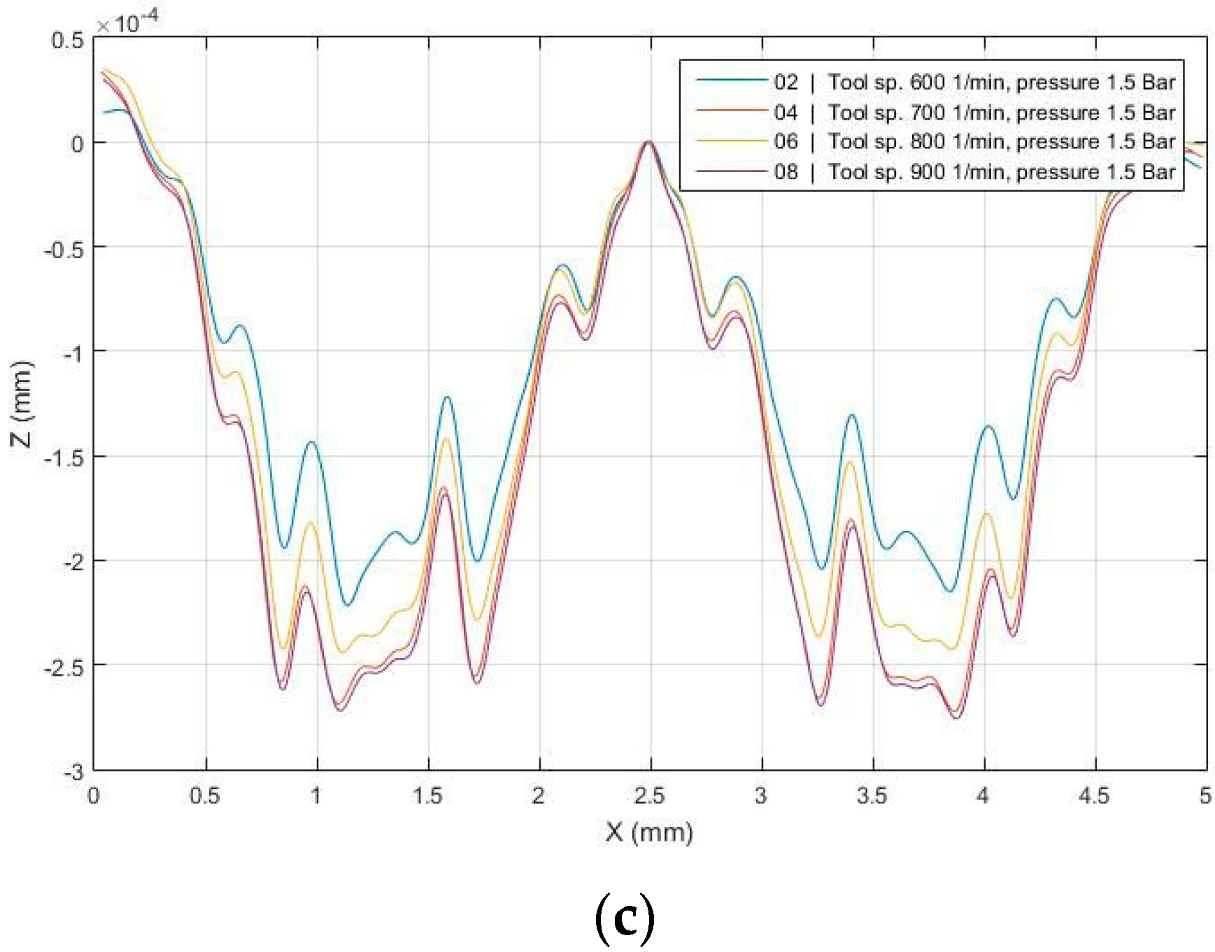
The results of the spot experiments performed on the YAG samples for the FEM tool are shown in Figure 3 and Figure 4, which confirm a significant difference in the real behavior of the tool from the theoretical model, manifested by ripple formation. Such complicated forms of the spots are difficult to fit mathematically and are, therefore, unsuitable for dwell time correction. The experiments also showed that an increase in tool speed led to an increase in material removal but had almost no effect on the shape of the polishing spot. In addition, it was evident that with an increase in pressure, the shape of the removal function changed. Consequently, it was deduced that the assumption that this tool design would ensure constant pressure was faulty. This was likely an effect associated with the small tool radius (necessary to control the spot size) and the inherent rigidity of the polyurethane polishing pad.
Two variants were tested for the VEH tool: a tool with a radius of R10 and a tool into whose head a planar surface with a diameter of 5.5 mm had been machined for the purpose of gluing on the polishing pad (R0). From the experiments performed (Figure 5), it was evident that in all cases, material removal increased when the tool speed rotation increased; however, this had no effect on the final shape of the polishing spots. Furthermore, in the case of the R10 spherical tool (Figure 5a), the material was polished out primarily by a very narrow ring, as the central part of the tool nearly failed to remove the material due to low circumferential speed and low polish penetration. The interaction between the pressure, the circumferential speed, and the distribution of the polishing slurry then resulted in the observed undulation, which was unsuitable for mathematical modeling of TIF using the Gaussian function.
In the case of the R0 tool, the situation was simpler, as the component of the variable pressure distribution was eliminated and, therefore, the resulting spot did not have such a tendency to ripple. However, a certain complication was caused by the increased sensitivity of the geometry of the planar tool–planar workpiece surface to mutual plane parallelism, where a small angular deviation led to a violation of uniformity in pressure distribution and material removal in the wedge (Figure 5b). Despite this complication, the planar tool option was considered more suitable for the YAG 3D shape correction.
Finally, the variant in which the spherical R10 tool was inclined by 15° from the normal of the polished surface was tested. In this arrangement, the tool rotary axis did not pass through the polishing spot, which led to a smaller decrease in the removal rate toward the center of the polishing spot. However, there was a rotationally asymmetrical distribution of circumferential speeds, which resulted in a characteristic deformation of the spot shape (Figure 6a) and thus unsuitability for the accurate fitting necessary for the dwell time correction. However, this phenomenon could be suppressed by sequential tilting of the tool rotation axis in the +X, +Y, −X, and −Y axes of the polishing device coordinate system (the so-called dynamic mode) [5], thus symmetrizing the shape of the polishing spot. This was confirmed by the results of the experiments performed using this method (Figure 6b).
For example, if we compare the results of the TIF mathematical fitting obtained by the Zeeko Precessions software for the FEM tool spot and for the VEH tool spot generated in dynamic mode with sequential tilting 15° in the +X, +Y, −X, and −Y axes, there was a significant reduction in the residual error of the TIF (Figure 7). This suggests the possibility of more accurate control of the dwell time corrective process.
4. Conclusions
Based on the performed experiments and the detected behavior of the various tools, the VEH R10 tool was selected, and the modified ring form presented in Figure 8 was chosen for the 3D corrective polishing of YAG laser rod faces.
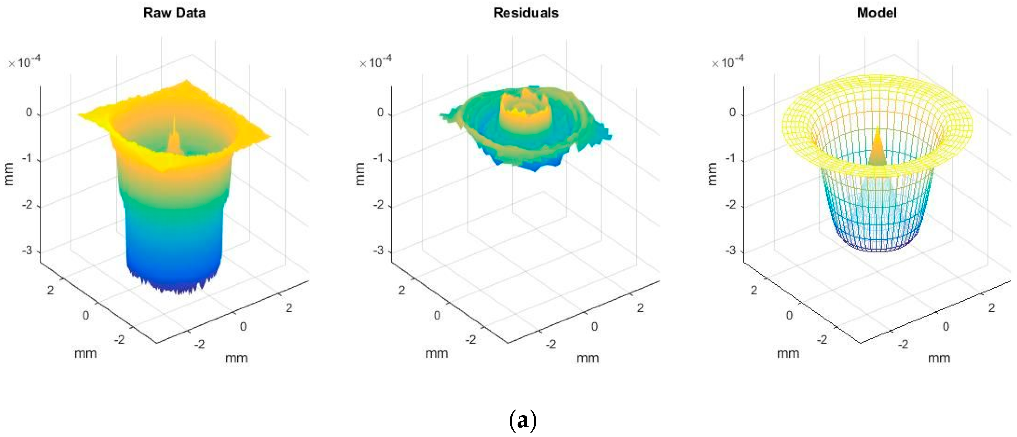
The polyurethane (PU) polishing pad was reduced to a ring, shaped by CNC machining for better control of the spot size and of the tool lateral resolution due to a reduction in the tool contact area at the YAG corrected surface and the tool mutual compression. The entire optimized process was then verified by a 3D correction of the 8 × 8 mm YAG plate in the Zeeko IRP 100, where the correction task was programmed in the Zeeko Precessions and Zeeko TPG software. The process parameters are shown in Table 2 and the correction results in Figure 9. In one 16-min correction step, the input shape error of 46 nm root mean square (RMS) was reduced to the value of 9 nm RMS. This satisfies the intended application both for shape accuracy and time consumption.
Author Contributions
Conceptualization and theoretical background, F.P. and K.N.; methodology and simulations, O.M.; experiment realization, J.B. and D.T.; result analysis and article writing, F.P. All authors have read and agreed to the published version of the manuscript.
Funding
This work was carried out within the sub-project “Laser rod faces characterization and 3D corrective micropolishing processes development (RMPT)” of the TACR NCK1 project “Center of electron and photonic optics” (number TN01000008), and co-funded by the European Structural and Investment Funds within the framework of the “Partnership for Excellence in Superprecise Optics” project (Reg. No. CZ.02.1.01/0.0/0.0/16_026/0008390).
Conflicts of Interest
The authors declare no conflict of interest.
References
- Murphy, P.E. Methods and challenges in quantifying mid-spatial frequencies. In Frontiers in Optics 2008/Laser Science XXIV/Plasmonics and Metamaterials/Optical Fabrication and Testing; Optical Society of America: Washington, DC, USA, 2008. [Google Scholar] [CrossRef]
- Zhang, J.; Wang, F.; Wang, G. Multi-Tool Sub-Aperture polishing High-Slope Asphere with Low Mid-Spatial Frequency Errors. In Proceedings of the 7th International Symposium on Advanced Optical Manufacturing and Testing Technologies: Advanced Optical Manufacturing Technologies, Harbin, China, 6 August 2014. [Google Scholar] [CrossRef]
- Wang, C.; Yang, W.; Wang, Z.; Yang, X.; Hu, C.; Zhong, B.; Guo, Y.; Xu, Q. Dwell-time algorithm for polishing large optics. Appl. Opt. 2014, 53, 4752–4760. [Google Scholar] [CrossRef] [PubMed]
- Yang, M.; Lee, H. Dwell time algorithm for computer-controlled polishing of small axis-symmetrical aspherical lens mold. Opt. Eng. 2001, 40, 1936–1943. [Google Scholar] [CrossRef]
- Walker, D.D.; Brooks, D.; King, A.; Freeman, R.; Morton, R.; McCavana, G.; Kim, S.W. The ‘Precessions’ tooling for polishing and figuring flat, spherical and aspheric surfaces. Opt. Express 2003, 11, 958–964. [Google Scholar] [CrossRef] [PubMed]
- Demmler, M.; Zeuner, M.; Allenstein, F.; Dunger, T.; Nestler, M.; Kiontke, S. Ion beam figuring (IBF) for high precision optics. In Proceedings of the Advanced Fabrication Technologies for Micro/Nano Optics and Photonics III, San Francisco, CA, USA, 16 February 2010. [Google Scholar] [CrossRef]
- Fang, H.; Guo, P.; Yu, J. Surface roughness and material removal in fluid jet polishing. Appl. Opt. 2006, 45, 4012–4019. [Google Scholar] [CrossRef] [PubMed]
- Kim, D.W.; Burge, J.H. Rigid conformal polishing tool using non-linear visco-elastic effect. Opt. Express 2010, 18, 2242–2257. [Google Scholar] [CrossRef] [PubMed] [Green Version]
- Kim, D.W.; Kim, S.W. Static tool influence function for fabrication simulation of hexagonal mirror segments for extremely large telescopes. Opt. Express 2005, 13, 910–917. [Google Scholar] [CrossRef] [PubMed] [Green Version]
- Roland, C.M. Mechanical Behavior of Rubber at High Strain Rates. Rubber Chem. Technol. 2006, 79, 429–459. [Google Scholar] [CrossRef]
- Plagge, J.; Klüppel, M. A physically based model of stress softening and hysteresis of filled rubber including rate- and temperature dependency. Int. J. Plast. 2017, 89, 173–196. [Google Scholar] [CrossRef]
- Tolpekina, T.V.; Pyckhout-Hintzen, W.; Persson, B. Linear and Nonlinear Viscoelastic Modulus of Rubber. Lubricants 2019, 7, 22. [Google Scholar] [CrossRef] [Green Version]
- Procháska, F.; Matousek, O.; Tomka, D.; Beneš, J.; Pechociakova, M. Concept of a polishing tool based on viscoelastic properties for midspatial frequencies suppression on aspheric surfaces. Opt. Eng. 2019, 58, 115102. [Google Scholar] [CrossRef]
Figure 1.
Material removal simulation for spherical tool with radius R1O mm for tool speed 800 1/min— flexible elastic membrane (FEM) with pressure of 1 bar (a); viscoelastic head (VEH) with ideal elastic behavior: elastic modulus of 10 MPa and relative deformation of 3% (b).
Figure 1.
Material removal simulation for spherical tool with radius R1O mm for tool speed 800 1/min— flexible elastic membrane (FEM) with pressure of 1 bar (a); viscoelastic head (VEH) with ideal elastic behavior: elastic modulus of 10 MPa and relative deformation of 3% (b).

Figure 2.
Example of white light interferometry (WLI) analysis results (FEM tool at 700 rpm with a pressure of 0.7 bar).
Figure 2.
Example of white light interferometry (WLI) analysis results (FEM tool at 700 rpm with a pressure of 0.7 bar).

Figure 3.
FEM R1O tool at 0 bar (a), 0.7 bar (b), and 1.5 bar (c).


Figure 4.
FEM R1O tool at 800 rpm for pressures of 0, 0.7, and 1.5 bar.

Figure 5.
VEH R10 (a) and R0 (b) tools.

Figure 6.
VEH R1O tool—tilting 15° in the +Y axis (a); symmetrization by sequential tilting 15° in the +X, +Y, −X, and −Y axes in the dynamic mode (b).
Figure 6.
VEH R1O tool—tilting 15° in the +Y axis (a); symmetrization by sequential tilting 15° in the +X, +Y, −X, and −Y axes in the dynamic mode (b).

Figure 7.
Tool influence function (TIF) fitting results comparison—FEM R10 tool (a); VEH R10 tool in the dynamic mode (b).
Figure 7.
Tool influence function (TIF) fitting results comparison—FEM R10 tool (a); VEH R10 tool in the dynamic mode (b).


Figure 8.
VEH R10 tool optimized for laser rod 3D correction.

Figure 9.
The 8 × 8 mm yttrium aluminum garnet Y3Al5O12 (YAG) plate 3D correction results—the VEH tool spot (a); the plate shape before correction (b); the plate shape after correction (c).
Figure 9.
The 8 × 8 mm yttrium aluminum garnet Y3Al5O12 (YAG) plate 3D correction results—the VEH tool spot (a); the plate shape before correction (b); the plate shape after correction (c).


Table 1.
Spot experiment conditions.
| Tool FEM R1O | Tool VEH R10 | Tool VEH R0 | |
|---|---|---|---|
| Dwell time (s) | 30 | 30 | 30 |
| Compression (mm) | 0.35 | 0.35 | 0.1 * |
| Tool speed (rpm) | 600; 700; 800; 900 | 600; 700; 800; 900 | 600; 700; 800; 900 |
| Pressure (bar) | 0; 0.7; 1.5 | - | - |
* A plane with a diameter of 5.5 mm was machined into the VEH tool head.
Table 2.
3D correction experiment settings.
| Tool | VEH (PU Pad) |
|---|---|
| Polishing slurry | Cerox |
| Tool tilt (°) | 15° (sequential in the +X, +Y, −X, and −Y axes) |
| Spot diameter (mm) | 2 |
| Kinematics | Raster (0.1 × 0.1 mm) |
| Tool speed (rpm) | 800 |
| Correction time (min) | 16 |
Publisher’s Note: MDPI stays neutral with regard to jurisdictional claims in published maps and institutional affiliations. |
© 2020 by the authors. Licensee MDPI, Basel, Switzerland. This article is an open access article distributed under the terms and conditions of the Creative Commons Attribution (CC BY) license (http://creativecommons.org/licenses/by/4.0/).
Share and Cite
MDPI and ACS Style
Prochaska, F.; Nejezchleb, K.; Benes, J.; Matousek, O.; Tomka, D. YAG Laser Rod 3D Corrective Process Optimization through Tool Influent Function Shape Inspection. Appl. Sci. 2020, 10, 8194. https://doi.org/10.3390/app10228194
AMA Style
Prochaska F, Nejezchleb K, Benes J, Matousek O, Tomka D. YAG Laser Rod 3D Corrective Process Optimization through Tool Influent Function Shape Inspection. Applied Sciences. 2020; 10(22):8194. https://doi.org/10.3390/app10228194
Chicago/Turabian StyleProchaska, Frantisek, Karel Nejezchleb, Jiri Benes, Ondrej Matousek, and David Tomka. 2020. "YAG Laser Rod 3D Corrective Process Optimization through Tool Influent Function Shape Inspection" Applied Sciences 10, no. 22: 8194. https://doi.org/10.3390/app10228194
Note that from the first issue of 2016, this journal uses article numbers instead of page numbers. See further details here.