Preparation and Characterization of a Selective Polymer-Based Solar Absorber for Building Integration


1
Institute of Building Structures, Faculty of Civil Engineering, Brno University of Technology, Veveří 331/95, 602 00 Brno, Czech Republic
2
Department of Material Engineering and Physics, Faculty of Civil Engineering, Slovak University of Technology, Radlinského 11, 810 05 Bratislava, Slovakia
3
Global Change Research Institute of the Czech Academy of Sciences, Bělidla 986/4a, 603 00 Brno, Czech Republic
*
Author to whom correspondence should be addressed.
Appl. Sci. 2020, 10(21), 7861; https://doi.org/10.3390/app10217861
Submission received: 17 September 2020
/
Revised: 4 November 2020
/
Accepted: 4 November 2020
/
Published: 6 November 2020
(This article belongs to the Special Issue Energy Efficient Envelope Technologies for Green, Healthy and Comfortable Buildings)
Abstract
:Featured Application
Prototype of a solar absorber for building integrated solar thermal applications.
Abstract
Recent technological advances in solar absorber production may have created opportunities for new applications of these materials in buildings. A low-emissivity enhanced polymer-based absorber foil was developed and prototyped to demonstrate feasibility of the concept. This paper describes key development factors leading to a particular composition of the prototype and its testing, specifically spectroscopy measurements (both for shortwave and longwave regions) and environmental impact assessment of its production. It also provides comparison of the tested parameters with commercially available absorbers. The results show that the developed absorber has relatively good thermal emissivity (approx. 0.3), high solar absorption (0.95) and selectivity (3.2), and significantly lower (up to 98%) environmental impacts compared to the commercially available metal-based solar selective absorbers.
1. Introduction
One solution to meet the global growth in energy demand is wider utilization of solar energy. This is one of the most challenging environmental ambitions influencing numerous industries, including building and construction [1]. Attention has focused on the development of various solar cells (thermal, photovoltaic, etc.) and collectors. One of the promising fields in this regard is the development of façade systems that integrate passive or active heating and cooling [2,3]. Such systems can increase the energy efficiency of buildings and help them achieve near-zero or even zero-energy performance levels. However, their successful integration requires finding synergy between thermal insulation of the façade in cooler periods and overheating in warmer periods.
Ongoing research projects, such as [4,5,6], strive to improve energy performance of buildings using solar heating and/or cooling. 6. Potential innovations include materials with reflective [7,8], solar [9,10], and selective [11] parameters able to work within a particular range of the thermal radiation spectrum. Research presented in the current study also contributes to this field. In this study, we developed a novel selective absorber technology for potential building integration that can prevent heat losses, influence overheating, and allow environmentally friendly conversion of incident solar energy into thermal energy [12].
Commercially available solar selective coatings applied in solar absorbers are produced from non-renewable resources (such as oil), whose reserves are declining due to increasing demand. This issue, combined with energy-intensive production (which also releases considerable greenhouse gas emissions) and questionable recyclability, are disadvantages of the use of these materials for sustainable construction. Furthermore, these issues have motivated researchers to identify new, renewable, and more environmentally friendly resources. Expensive high-tech technologies exist, such as the production of nanostructures. In addition, low-tech and low-cost polymeric photonic technologies appear to present a viable option for the present and the near future [13]. Therefore, it is desirable to develop a coating with high structural stability (with dependable production processes) to reduce the cost and environmental impact of solar absorbers, [14].
Another characteristic of many solar absorbers, such as the stable cermets of conductive ceramics TiN in SiO2 [15], is that they are designed for operating temperatures of 300 °C and higher [16]. Such temperatures are appropriate for solar thermal systems [17,18,19]. However, it has been also shown [20] that a suitable design of an absorber system integrated in a building facade can reach a maximum temperature of approx. 80 °C. This enables the use of less demanding (and expensive) materials, such as polymers, for the production of absorbers, resulting in notable economic and environmental benefits. Overall, polymer-based products are likely to be commonly used in the future due to their significant advantage over other non-polymer nanophotonic materials in terms of manufacturability and cost [21]. The key attributes for the newly developed solar absorber material described in this paper are therefore low cost; high absorption of solar radiation (αs > 0.9); medium emissivity (ε < 0.4); high durability in the context of long-term operating temperature of at least 80 °C; low environmental impacts; easy applicability to common building surfaces; and production with readily available industrial technologies (in the context of developed or developing regions, such as Central Europe).
Recent development of solar selective absorbers highlights the need for cost-effective and environmentally friendly materials with high selectivity and durability [22]. Both of these parameters heavily depend on efficient resource consumption (energy, materials, etc.). In this regard, construction of a selective solar absorber can be based on a number of concepts [23]. One of the available concepts is a thickness insensitive coating, in which low-emissivity flakes are embedded in a suitable binder with a pigment with high solar absorption. Such a coating can be applied on various substrates; however, its low emissivity and price are questionable. Another concept utilizes a thickness sensitive coating. This requires a low-emissivity surface (such as aluminum) covered by a layer of material with high absorption of shortwave radiation and, simultaneously, transparency for longwave radiation.
The thickness of the coating is usually less than 5 microns. Such a thickness can be easily achieved by “high-tech” methods such as vacuum deposition [24,25] or ion deposition. These methods can produce an absorbent layer with a thickness of about 40 nm, which is sufficient to reduce surface emissivity below ε = 0.05. Such technology is commonly used, e.g., in the packaging industry [26], microelectronics, photovoltaics or optics [27,28]. However, “low-tech” methods also exist, such as painting [29,30], which can be sufficiently accurate (for the intended purpose) in the controlled environment of an industrial production line. Other options include chemical deposition [31] or treatment of the low-emissivity substrate [23]. However, these have disadvantages, such as the wet process or potentially harmful chemicals. Finally, solar absorbers can be based on a thin polymer foil dyed with suitable dark pigment. This foil can be attached to a low-emissivity surface or directly metalized, e.g., by vacuum deposition.
In conventional building applications (solar thermal systems, solar walls), the metal is also present as a structural element in the form of a sheet (metal thickness of at least 0.2 mm). However, previous research identified high environmental impacts of metal in this role [32,33]. Therefore, the developed absorber presented in this paper utilizes metal only for its impact on emissivity. The structural role is transferred to the underlying material to which it will be attached. Dyed polyolefin laminate backed by a low-emissivity substrate was selected as a relevant option for such a low-cost environmentally-friendly solution. Another important aspect is that although a need may exist for a specific industrial production line (such as an industrial line for blowing-out the foil and in-line vacuum deposition facility), it is possible to purchase machine time, thus allowing the production to be managed without significant capital investment. Low emissivity barriers [34] and reflective foils [35] have been widely investigated in buildings when opaque building components are designed. However, although existing works (such as [36,37]) suggest that a solar selective absorber is a viable option for the reduction of heating energy consumption, a literature review did not identify an existing solar absorber foil that could be potentially integrated for innovative energy-efficient building-envelope applications.
2. Materials and Methods
The absorber developed in the presented research utilizes a polymer-based absorption layer colored with an inorganic pigment. This concept allows a low infrared (IR) absorption rate due to the bond matrix and tolerance to pigment thickness variation. The key aim of the presented research was therefore investigation of the spectral optical performance of the developed absorber samples and other comparable spectrally-selective solar absorbers, at both solar radiation and longwave radiation levels. Reflective measurements and spectral methods were applied to determine the solar reflectance in the visible (VIS) and the near infrared (NIR) region, and the thermal emissivity of the samples. This analysis is crucial for detailed examination of the heat transfer phenomena at the boundary with the surrounding built and urban environment. However, the developed absorber should not be only optically comparable to existing products; it should also reduce environmental impacts of buildings. Therefore, another aim of the presented research is a life cycle assessment that focuses on embodied environmental impacts related to the production of the developed absorber.
2.1. Material Preparation and Final Selection
Two absorber concepts with different materials and production technology were investigated in the initial research phase. The first concept was a paint with alcohol-based organic pigment. Its advantage was that it could be applied with a 50 mm wide felt tip marker. However, in the case of application on a 0.02 mm thick aluminum foil, the pigment layer was prone to leafing. A 0.3 mm aluminum plate was necessary to provide an optimal low-emissivity substrate. The second concept was a polyolefin laminate combined with manganese ferrite black spinel pigment (0.5 µm mean diameter of particles). Due to its better mechanical stability, it was possible to incorporate the pigment in high-density polyethylene (HDPE) (5% by mass). The HDPE was processed on a semi-industrial blow-out line. The resulting foil was subsequently attached to a low-density polyethylene (LDPE) metalized laminate by hot pressing (20 min; 140 °C; 0.1 MPa).
The second concept was selected to be more promising for further development after the initial spectral optical measurements based on the results of the tests, previous work experience, and a literature review (see Section 1). It was assumed that a polymer-based absorber foil would have advantages of easier transportability, and lower production costs and environmental impacts, compared to an absorber incorporating metal plates. This resulted in selection of biaxially oriented polypropylene (BOPP) and metalized polyethylene terephthalate (MPET) foils as possible substrate materials for the final absorber concept. Both are well-established materials (in the context of Central Europe) with suitable parameters. BOPP is more compatible with a polyethylene absorption layer, but it has lower thermal resistance. MPET has high tensile strength (150 MPa), stiffness, and temperature resistance (up to 140 °C), ensuring acceptable mechanical properties at the intended operating temperatures around 80 °C. This selection was followed by further development of the production process. Industrial roll-to-roll processing was selected because it is a readily available technology with an acceptable production rate (up to a few meters per second), sufficiently low costs, and sufficient pigment thickness control. It also enables reprocessing of technological waste and works without further materials, such as solvents in printing technologies (which is beneficial for the mitigation of environmental impacts).
The final composition of the developed polymer-based solar absorber therefore consists of a polyethylene absorbent layer with 5% (by mass) inorganic pigment, an adhesive polyethylene bridge, vapor-coated aluminum, and a structural layer of MPET (see Figure 1). In standalone applications, a UV stabilizer should be incorporated, however, it was not used in the current development stage.
2.2. Tested Materials
As mentioned in previous sub-sections, samples of the developed absorber were spectrally analyzed to evaluate their optical performance. Samples of six other absorbers were also analyzed for comparison purposes: three samples of black painted absorbers (S1–S3) and three samples of commercially available selective absorbers (R1–R3) that were characterized in the authors’ previous work [20]. An overview of the tested samples is presented in Table 1.
2.3. Spectral Optical Measurements
Solar reflectance measurements were based on measurement of the fraction of the incident beam light of the wavelength reflected by a surface. A Lambda 1050 UV/VIS/NIR spectrophotometer (PerkinElmer, Waltham, MA, USA) equipped with a 150 mm Spectralon integrating sphere was used for this purpose. This device can register spectral reflectance properties from 200 to 3300 nm. Spectral curves and integrated total solar reflectance (TSR) values from 280 to 2500 nm are provided. The solar reflectance was calculated using the method of (ASTM) G173 standard [38] for hemispherical global tilt irradiance for air mass 1.5, and each specific region is demonstrated. This is described in Equation (1), where R is the percent reflectance, I is the solar irradiance, and dλ is the wavelength interval of integration:
The available principles for the determination of spectral emissivity (reflectance) are based on spectral analysis with infrared spectroscopy in the longwave region. Reflective measurements utilizing a Michaelson wave interferometer and Fourier transform (FT-IR) were selected for this purpose. Therefore, a Nicolet 380 infrared spectrometer from the Thermo Electron Corporation (Waltham, MA, USA) equipped with a Mid-IR™ IntegratIR integrating sphere from PIKE Technologies (Madison, WI, USA) was used. This device can eliminate any reflected radiation loss by integrating a sphere from the whole measured surface area. The principle of the test is to measure the specimen on the reflection of the beam (angle of incidence of 8°) of infrared radiation ranging from 2.5 to 18 μm of wavelength. The weighted average reflectance was calculated for 80 °C. Subsequently Equation (2) based on the law of the conservation of energy and Kirchhoff’s laws was used for determination of the measurement results in terms of emissivity values:
ε = α = 1 − ρ, or ελ = αλ = 1 − ρλ
Consequently, Plank’s formula (Equation (3)) of spectral radiance intensity of 80 °C (353 K) black body M0, λ as the weighted function for determination of emissivity values was applied:
Finally, the simplified calculation of the optical efficiency was performed using two parameters: selectivity (f) and figure of merit (FM, e.g., in [39,40]) according to Equation (4). The first parameter can practically and effectively characterize performance as the selectivity parameter [41] with higher f indicating more selective material. However, it should be noted that the optical efficiency is affected by other parameters of a particular absorber application. Therefore, high selectivity does not necessarily indicate the best absorber [42]. For this reason, in the presented calculation of FM, by neglecting convection and conduction heat loss and following boundary conditions, it is assumed: 1000 W∙m−2 incidence solar radiation (G), 80 °C operating temperature of the absorber (TA), and 0 °C ambient temperature e.g., sky (Tsky).
2.4. Life Cycle Assessment (LCA)
LCA is a well-established method for multi-criteria evaluation of environmental impacts of products (see, e.g., [43]). It is especially useful in comparative studies, where it provides a complex basis for the decision-making process [44]. Its general framework is defined in ISO 14040 [45]. This ISO standard is rather vague for the purposes of the presented study. Therefore, the boundary conditions and specifications for building-material-related LCAs described in European standard EN 15804 [46] were also applied.
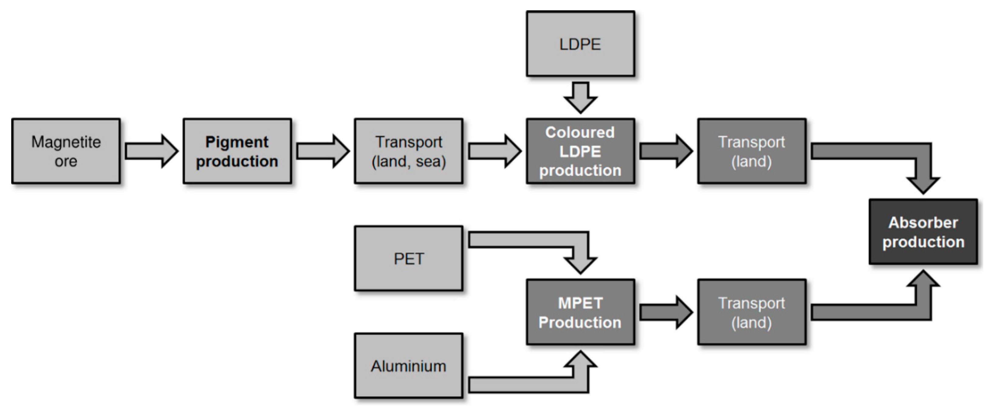
The presented research utilized LCA to support decision making during the development of the prototype absorber composition and production process. The LCA presented in this paper shows environmental impacts related to the production of the final absorber prototype (see scheme in Figure 2) and compares them with environmental impacts of the production of S3, R2, and R3 absorbers (as representatives of the S1–S3 and R1–R3 absorbers). The selection of production process corresponds with “cradle-to-gate” system boundaries (modules A1–A3) defined as one of the options for product LCA in EN 15804. Installation, maintenance, or disposal (modules A4–D according to EN 15804) of the absorbers were omitted at this stage of the absorber development because they are the focus of ongoing research. The addition of hypothetical scenarios representing these life cycle stages would needlessly reduce the accuracy of the comparison. However, previous work [47] clearly shows that environmental impacts of these stages could overshadow the production stage. They can even justify the initial increase in environmental impacts by operational energy savings. Future LCAs will therefore cover the whole life cycle of the absorber.
The LCA presented in this paper considered the following boundary conditions and simplifications:
- The environmental impacts were calculated using 13 impact categories defined in EN 15804 (with amendment A2). The results are presented using both the impact category indicators and normalized indicators (transformed to “person equivalents”) to increase clarity.
- The environmental impacts were calculated in the GaBi software with the ecoinvent 3.6 database.
- The declared unit of the LCA is 1 m2 of the absorber. This equals 42 g of P1, 300 g of S3, 1795 g of R2, and 813 g of R3 absorbers. The selection of the declared unit is based on information in EN 15804 and following standards.
- Production losses of 5% were considered during production of the P1 absorber based on information from the operator of the production line. Landfill is considered the worst-case production waste management scenario.
- Only primary raw materials were considered to provide the worst-case scenario results.
- No packaging was considered.
- The hypothetical final production site for the P1 absorber was set to Brno, Czech Republic. This was reflected in transport of raw materials from suppliers (transport of MPET from Germany, pigment from Norway, and LDPE from Czech Republic).
- Data on the production of the absorbers and related raw materials were assigned to suitable ecoinvent datasets. The database however does not contain datasets representing pigment and MPET production. Pigment production was therefore modelled based on data from a Norwegian producer and MPET production was modelled based on [48]. Both of their models include raw material supply, production process, and (major) waste management.
3. Results
3.1. Evaluation of Spectral Optical Parameters
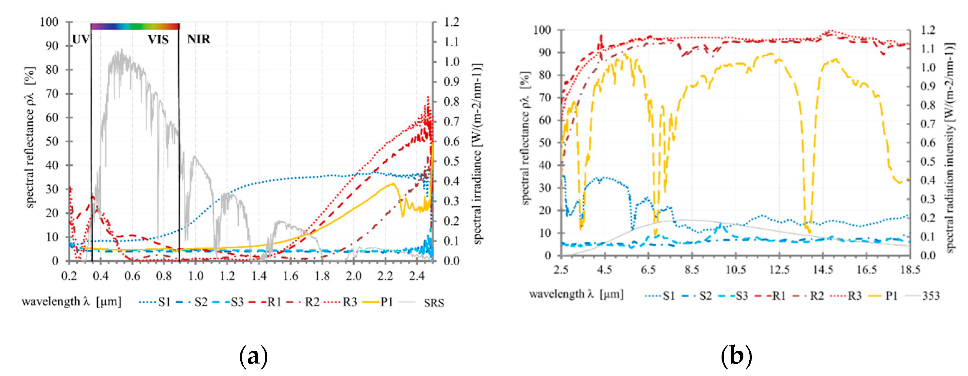
Figure 3 shows the results of the spectral measurements of the samples in the range from 200 nm to 18 μm. The charts in the figure represent all thermal regions of the electromagnetic spectrum. Figure 3a shows the spectral irradiance curve of the solar radiation spectrum (SRS) in the UV/VIS/NIR results (absorbance in shortwave spectrum). Figure 3b shows the curve of the spectral radiance intensity of a 353 K (80 °C) black body representing the weighted function for the determination of emissivity in the results of the longwave IR range (longwave spectrum). Table 2 sums the results of the spectral reflectance analysis: thermal emissivity and solar absorbance of the tested absorbers. In addition, the table also shows the selectivity of the absorbers (the ratio between both parameters) and figure of merit (FM; calculated based on [39,40]). This shows that all evaluated absorbers have almost the same solar absorbance (from 0.90 to 0.95), whereas their emissivity notably varies. The developed P1 absorber has emissivity of around 0.3 in the longwave radiation spectrum, which is approx. 60% lower than the S1–S3 paint-based absorbers but higher than those of the selective types. As a result of filtration of some regions’ results (3.5, 7.0, and 14.0), the difference is up to 25% compared to the evaluated selective solar absorbers R1–R3. This fact is also evident for the level of selectivity. Results show that commercially available absorbers can be considered to be highly selective, with selectivity values ranging from 13.6 to 23.5. In comparison, the developed P1 absorber achieves selectivity of 3.2 and paints S1–S3 achieve selectivity of only 1.0. This means that P1 achieves FM = 0.78, while R2 and R3 achieve FM = 0.91 and 0.92, respectively, for the theoretical case with absorber operating temperature of 80 °C (the best theoretical efficiency is 1.0 for an ideal absorber with α = 1 and ε = 0).
3.2. Evaluation of Environmental Impacts
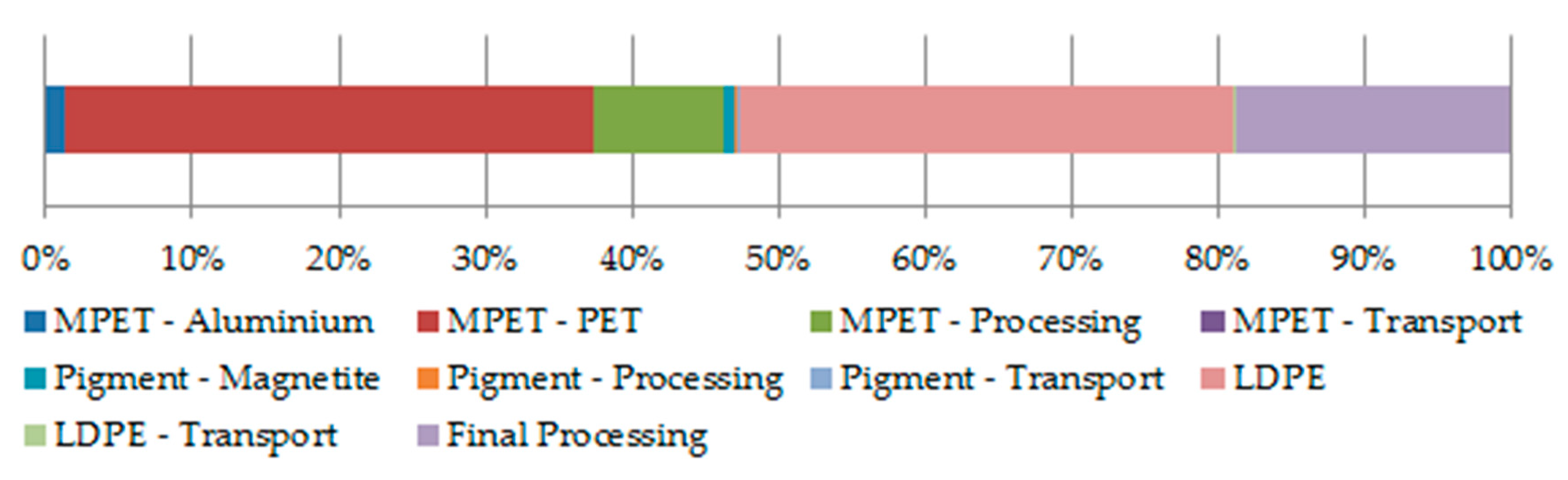
Results of the LCA regarding environmental impacts of the developed P1 absorber’s production are summarized in Table 3 and Figure 4. Table 3 shows environmental impacts of the P1 absorber divided per individual impact category, material, and process (in accordance with the production scheme in Figure 2). Figure 4 provides further insight into the numerical results by showing shares of the materials and processes relative to the sum of normalized environmental impacts. Both the table and the figure identify pigment production as the least environmentally demanding (less than a 0.1% share of the sum of normalized results in Figure 4). This is followed by transport. Although the sum of transport distances is close to 3000 km, this only accounts for 0.4% of the sum of normalized results. In contrast, PET and LDPE have the highest and second highest environmental impacts in most categories. Their shares of the sum of normalized results are 36% and 34%, respectively.
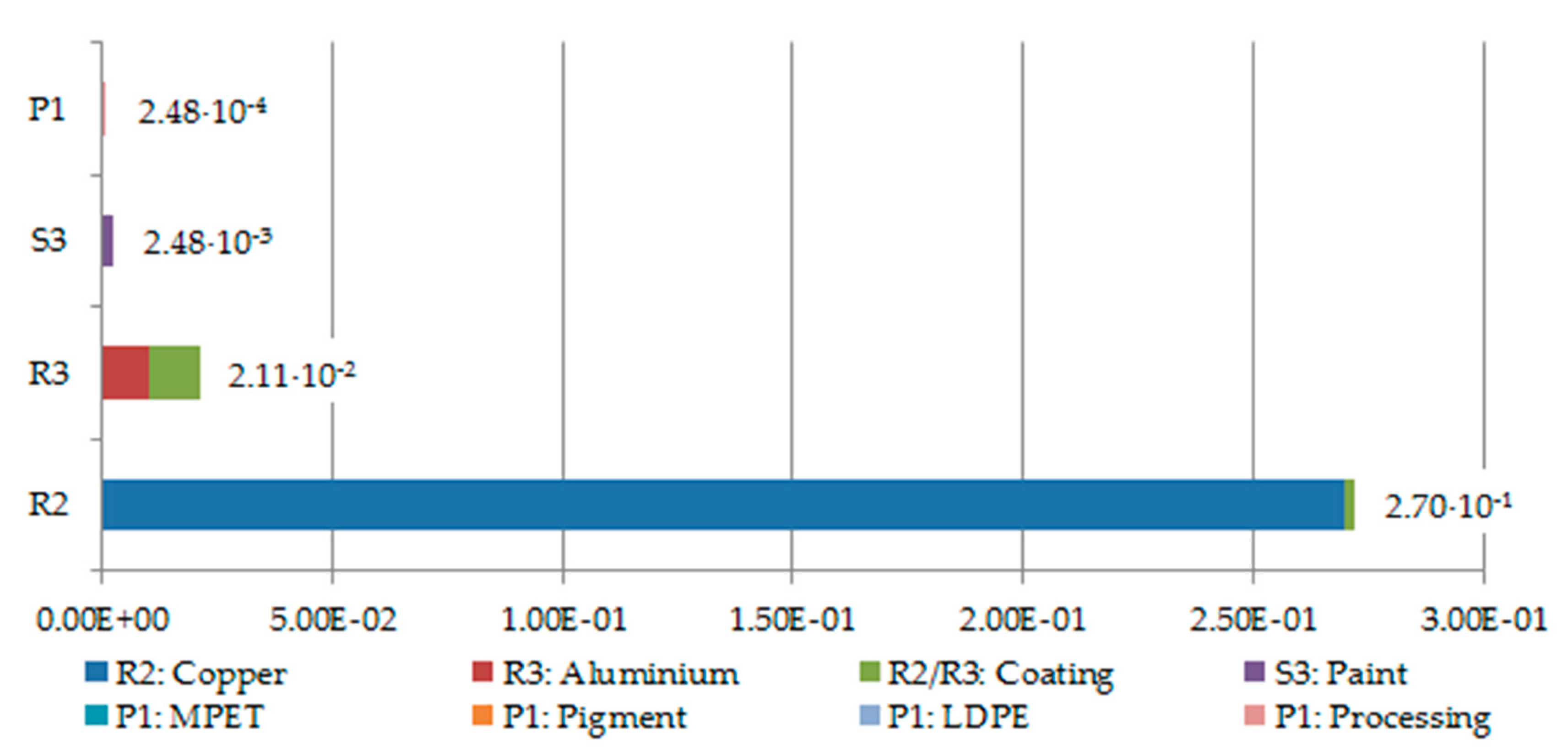
Table 4 shows total environmental impacts of the P1 absorber, in addition to those of the R2 and R3 TiNOx absorbers and S3 synthetic coating. It shows that the P1 absorber has the lowest impact in 12 of the 13 categories. The difference is at least 98% compared to R2 and R3, and at least 83% compared to S3. The sums of normalized environmental impacts in Figure 5 further highlight the environmental efficiency of the P1 absorber, particularly when compared to TiNOx absorbers incorporating a comparatively high amount of metals.
4. Discussion
Previous sections describe the development of the new solar absorber and compare its spectral parameters and environmental performance with commercially available products. The results provide several points for discussion:
- Optical parameters. The performance data presented in Table 2 can be utilized to determine the efficiency of the compared absorbers in various solar thermal applications (e.g., solar thermal collectors in [30,42]). P1, S3, and R2 absorbers share the best solar absorbance (αλ = 0.95). This means that they would also have identical net absorbed energy. The results also show that thermal emissivity of the developed P1 absorber is approximately 25% worse than that of commercial selective absorbers R1–R3 due to the presence of the polyethylene absorbent layer. Thermal emissivity is a key parameter for the determination of the heat transfer coefficient and the heat loss of any solar thermal system (e.g., solar facades with selective absorbers as described in [12,20,33,49]). When evaluating efficiency of the absorber, both parameters should be included in the selectivity parameter. In general, changes in selectivity do not adequately reflect how it affects the system efficiency. A particular solar thermal application needs to be specified for it to properly identify the theoretical efficiency of a solar absorber. Then, a figure of merit (FM) representing the efficiency can be calculated. In this paper a simple theoretical case of 80 °C absorber temperature and incidence solar radiation of 1000 W∙m−2 was utilized for this purpose. The ratio of the net solar power absorbed by the system (i.e., absorbed power minus radiated power) to the incident power in the system simply conveys the system efficiency. Compared to the ideal absorber, due to emissivity changes of all of the evaluated absorbers, the decrease in efficiency varies: 22% (P1), 58% (S3), and 8–9% (e.g., R2 and R3). This makes the developed P1 absorber only slightly less efficient (up to 14%) compared to the R2 and R3 absorbers. However, it should be noted that the difference is related to ambient temperature: a smaller difference between the absorber temperature and ambient temperature reduces the difference in the efficiency of the absorbers.
- Environmental impacts. The LCA quantified the environmental impacts related to the production of the developed P1 absorber. It identified (primary) plastics and their processing as major contributors. This means that utilization of recycled materials (in accordance with circular economy principles) and renewable energy sources could further improve the environmental performance of the absorber. Such improvement would also benefit other compared absorbers, especially TiNOx-based R2 and R3, because the LCA confirmed that their high environmental impacts are related to the metal substrate (as already indicated in [33]). In fact, the results show that primary aluminum and copper have approx. 49% and 99% shares of the normalized environmental impacts of the respective absorbers (due to the energy intensity of the metal processing). However, even following a 90% reduction of the embodied environmental impacts of recycled metals, as suggested in the literature (e.g., [50]), the developed absorber would still be superior.
- Operating temperature. This is one of the key parameters for operation of the spectral selective coatings. Some of the existing material concepts are limited by the operating temperature, e.g., up to 200 °C or less. However, the intended application (in building envelopes) does not presuppose exceeding 100 °C. In this range, the suggested polymer-based foil absorber should perform adequately, considering its intended building integration.
- Operating conditions. The absorber foil could be damaged by the environment (dust or other mechanical threats, UV radiation, etc.). It does not require the same level of protection as an evacuated solar thermal system. Nonetheless, it is expected that (in the context of a solar wall) the absorber will be installed behind a transparent element (glass or a transparent insulation material) that will provide sufficient protection. As suggested in Section 2.4., this would influence the environmental performance of the absorber. Thus, a full cradle-to-grave LCA is necessary to confirm environmental advantages of the developed absorber compared to its competitors.
- Heat transfer. Primarily, the developed absorber is intended for passive air heating with the possibility of heating the base material. This is advantageous in contrast to elements intended for water heating because it is not necessary to consider the efficiency of heat transfer to another medium. Therefore, as noted in the previous point, it is appropriate to consider solutions using polymer-based foils, etc.
- Production options. The developed absorber can be produced in a new production facility. However, this would result in unnecessarily high investment costs. Thus, the development of the absorber aims at utilization of already proven (and commercially available) solutions. This would reduce the need of high investment and make the production easily achievable in various locations.
5. Conclusions
The presented research aims at the development of a suitable spectrally selective surface technology that can be used in solar thermal applications in building envelopes (e.g., solar walls for passive heating, as in [36,37]). The paper describes the reasoning behind the development of the low-cost polymer-based foil solar absorber, analysis of its spectral optical parameters, and environmental assessment of its production. These are compared with parameters of commercially available absorbers. The results indicate that the developed absorber can be applied in situations in which activation of the selective functions of its surface layers is beneficial for the thermal performance of the building envelope (regarding the heat transfer phenomena).
The results of spectral optical analysis are presented in the form of spectral curves and reflectance radiative parameters. It is shown that the developed absorber has very good solar absorbance (95%). This is comparable with the best of the tested commercial products. It also has acceptably low emissivity (30%) of thermal radiation. Furthermore, the LCA of the developed absorber shows that it is considerably more environmentally friendly than the commercial products. The difference is at least 98% compared to TiNOx absorbers and 83% compared to a synthetic paint. This difference could be further increased by utilization of secondary raw materials (and renewable energy sources).
The presented study suggests several future research and development prospects:
- Feasibility. The presented study compared parameters of the developed absorber with those of several commercially available products. In conjunction with better performance, the developed absorber should also be able to compete with the commercially available products in terms of investment cost. A life cycle cost analysis should be performed to address this issue.
- Durability. As mentioned before, the durability of the polymer-based foil is likely lower than that of metal-based products. Therefore, future research should include testing of environmental resistance (UV, mechanical durability, etc.) and development of suitable inbuilding options that protect the foil.
- Color design. The integrated façade element will influence the overall aesthetics of the building. In terms of efficiency, the best color option is black, however “sacrificing” about 10–15% of absorption performance would allow a wider range of dark color options.
- Environmental impacts. The drawbacks of the presented LCA are mentioned in Section 4. These indicate the need for further research of the whole life cycle of the absorber, including installation, maintenance, and disposal. This would allow identification of the most efficient means of application in buildings.
- Energy efficiency. A whole life cycle perspective is also necessary from the perspective of energy efficiency. This means adding the operational energy balance to the calculations of performance and energy savings (and related environmental impacts) achievable by the installation of the absorber in various conditions (cardinal orientation of the surface, climate, etc.). Combined with further optimization of physical parameters and the production process, this would lead to an optimal balance of environmental and monetary savings for the users of buildings.
Author Contributions
Conceptualization, M.Č. and D.K.; methodology, M.Č., D.K. and K.S.; software, K.S.; formal analysis, K.S.; investigation, M.Č., D.K. and K.S.; resources, K.S.; data curation, M.Č., D.K. and K.S.; writing—original draft preparation, M.Č. and K.S.; writing—review and editing, M.Č. and K.S.; visualization, K.S.; supervision, M.Č.; project administration, M.Č.; funding acquisition, M.Č. All authors have read and agreed to the published version of the manuscript.
Funding
Grantová Agentura České Republiky: GA 20-00630S; Vedecká grantová agentúra MŠVVaŠ SR a SAV: VEGA 1/0680/20.
Acknowledgments
This research was supported by Czech Science Foundation, project GA 20-00630S “Climate responsive components integrated in energy and environmentally efficient building envelope” and VEGA 1/0680/20 supported by the Scientific Grant Agency of the Ministry of Education, Science, Research and Sport of the Slovak Republic.
Conflicts of Interest
The authors declare no conflict of interest. The funders had no role in the design of the study; in the collection, analyses, or interpretation of data; in the writing of the manuscript, or in the decision to publish the results.
References
- Buker, M.S.; Riffat, S.B. Building integrated solar thermal collectors–A review. Renew. Sustain. Energy Rev. 2015, 51, 327–346. [Google Scholar] [CrossRef]
- Luo, Y.; Zhang, L.; Bozlar, M.; Liu, Z.; Guo, H.; Meggers, F. Active building envelope systems toward renewable and sustainable energy. Renew. Sustain. Energy Rev. 2019, 104, 470–491. [Google Scholar] [CrossRef]
- Prieto, A.; Knaack, U.; Auer, T.; Klein, T. COOLFACADE: State-of-the-art review and evaluation of solar cooling technologies on their potential for façade integration. Renew. Sustain. Energy Rev. 2019, 101, 395–414. [Google Scholar] [CrossRef]
- Bonato, P.; Fedrizzi, R.; D’Antoni, M.; Meir, M.; Kostro, A.; Hafner, A.; Souto, A.V.; Arregi, B.; Copertaro, B.; Wilkinson, B.; et al. State-of-the-Art and SWOT Analysis of Building Integrated Solar Envelope Systems; Technical Report: IEA Task56 DA1 DA2; International Energy Agency: Paris, France, 2019; 103p. [Google Scholar] [CrossRef]
- Garshasbi, S.; Santamouris, M. Using advanced thermochromic technologies in the built environment: Recent development and potential to decrease the energy consumption and fight urban overheating. Sol. Energy Mater. Sol. Cells 2019, 191, 21–32. [Google Scholar] [CrossRef]
- Ürge-Vorsatz, D.; Khosla, R.; Bernhardt, R.; Chan, Y.C.; Vérez, D.; Hu, S.; Cabeza, L.F. Advances Toward a Net-Zero Global Building Sector. Annu. Rev. Environ. Resour. 2020, 45, 227–269. [Google Scholar] [CrossRef]
- Jin, L.Q.; Xu, Q.-H. Preparation of Hollow Microsphere and its Application in Paper Coating. Adv. Mater. Res. 2013, 652, 740–744. [Google Scholar] [CrossRef]
- Jia, M.Q.; Jin, Y.H. Performance of Thermal Insulation Reflective Composite Coatings. Adv. Mater. Res. 2011, 239, 1771–1774. [Google Scholar] [CrossRef]
- Richter, A.; Hermle, M.; Glunz, S.W. Reassessment of the Limiting Efficiency for Crystalline Silicon Solar Cells. IEEE J. Photovolt. 2013, 3, 1184–1191. [Google Scholar] [CrossRef]
- Kanama, D.; Kawamoto, H. Research and development trends of solar cell for highly efficiency. Q. Rev. 2008, 4, 57–74. [Google Scholar]
- Orel, C.Z.; Klanjšek, G.M. Spectrally selective paint coatings: Preparation and characterization. Sol. Energy Mater. Sol. Cells 2011, 68, 337–353. [Google Scholar] [CrossRef]
- Čekon, M.; Čurpek, J. A transparent insulation façade enhanced with a selective absorber: A cooling energy load and validated building energy performance prediction model. Energy Build. 2019, 183, 266–282. [Google Scholar] [CrossRef]
- Santamouris, M.; Feng, J. Recent Progress in Daytime Radiative Cooling: Is It the Air Conditioner of the Future? Buildings 2018, 8, 168. [Google Scholar] [CrossRef] [Green Version]
- Zhang, K.; Hao, L.; Du, M.; Mi, J.; Wang, J.-N.; Meng, J.-P. A review on thermal stability and high temperature induced ageing mechanisms of solar absorber coatings. Renew. Sustain. Energy Rev. 2017, 67, 1282–1299. [Google Scholar] [CrossRef]
- Cao, F.; Tang, L.; Li, Y.; Litvinchuk, A.P.; Bao, J.; Ren, Z. A high-temperature stable spectrally-selective solar absorber based on cermet of titanium nitride in SiO2 deposited on lanthanum aluminate. Sol. Energy Mater. Sol. Cells 2017, 160, 12–17. [Google Scholar] [CrossRef] [Green Version]
- Gao, X.-H.; Guo, Z.-M.; Geng, Q.-F.; Ma, P.-J.; Wang, A.; Liu, G. Enhanced optical properties of TiN-based spectrally selective solar absorbers deposited at a high substrate temperature. Sol. Energy Mater. Sol. Cells 2017, 163, 91–97. [Google Scholar] [CrossRef]
- Selvakumar, N.; Manikandanath, N.; Biswas, A.; Barshilia, H.C. Design and fabrication of highly thermally stable HfMoN/HfON/Al2O3 tandem absorber for solar thermal power generation applications. Sol. Energy Mater. Sol. Cells 2012, 102, 86–92. [Google Scholar] [CrossRef]
- Jyothi, J.; Chaliyawala, H.; Srinivas, G.; Nagaraja, H.; Barshilia, H.C. Design and fabrication of spectrally selective TiAlC/TiAlCN/TiAlSiCN/TiAlSiCO/TiAlSiO tandem absorber for high-temperature solar thermal power applications. Sol. Energy Mater. Sol. Cells 2015, 140, 209–216. [Google Scholar] [CrossRef]
- Chen, H.-P.; Lee, C.-T.; Liao, W.-B.; Chang, Y.-C.; Chen, Y.-S.; Li, M.-C.; Lee, C.-C.; Kuo, C.-C. Analysis of High-Efficiency Mo-Based Solar Selective Absorber by Admittance Locus Method. Coatings 2019, 9, 256. [Google Scholar] [CrossRef] [Green Version]
- Čekon, M.; Slávik, R. A Non-Ventilated Solar Façade Concept Based on Selective and Transparent Insulation Material Integration: An Experimental Study. Energies 2017, 10, 815. [Google Scholar] [CrossRef] [Green Version]
- Zhao, D.; Aili, A.; Zhai, Y.; Xu, S.; Tan, G.; Yin, X.; Yang, R. Radiative sky cooling: Fundamental principles, materials, and applications. Appl. Phys. Rev. 2019, 6, 021306. [Google Scholar] [CrossRef]
- Amri, A.; Jiang, Z.T.; Pryor, T.; Yin, C.Y.; Djordjevic, S. Developments in the synthesis of flat plate solar selective absorber materials via sol–gel methods: A review. Renew. Sustain. Energy Rev. 2014, 36, 316–328. [Google Scholar] [CrossRef] [Green Version]
- Xu, K.; Du, M.; Hao, L.; Mi, J.; Yu, Q.; Li, S. A review of high-temperature selective absorbing coatings for solar thermal applications. J. Mater. 2020, 6, 167–182. [Google Scholar] [CrossRef]
- Bishop, C.A. Vacuum Deposition onto Webs, Films and Foils, 3rd ed.; William Andrew Publishing: Norwich, NY, USA, 2016; 602p. [Google Scholar]
- Selvakumar, N.; Barshilia, H.C. Review of physical vapor deposited (PVD) spectrally selective coatings for mid- and high-temperature solar thermal applications. Sol. Energy Mater. Sol. Cells 2012, 98, 1–23. [Google Scholar] [CrossRef]
- Lindner, M.; Schmid, M. Thickness Measurement Methods for Physical Vapor Deposited Aluminum Coatings in Packaging Applications: A Review. Coatings 2017, 7, 9. [Google Scholar] [CrossRef] [Green Version]
- Wu, X.; Zhou, Z.; Wang, Y.; Li, J. Syntheses of Silver Nanowires Ink and Printable Flexible Transparent Conductive Film: A Review. Coatings 2020, 10, 865. [Google Scholar] [CrossRef]
- Rydosz, A. The Use of Copper Oxide Thin Films in Gas-Sensing Applications. Coatings 2018, 8, 425. [Google Scholar] [CrossRef] [Green Version]
- Jerman, I.; Koželj, M.; Orel, B. The effect of polyhedral oligomeric silsesquioxane dispersant and low surface energy additives on spectrally selective paint coatings with self-cleaning properties. Sol. Energy Mater. Sol. Cells 2010, 94, 232–245. [Google Scholar] [CrossRef]
- Orel, Z.C.; Gunde, M.K.; Lenček, A.; Benz, N. The preparation and testing of spectrally selective paints on different substrates for solar absorbers. Sol. Energy 2001, 69, 131–135. [Google Scholar] [CrossRef]
- Huang, T.-C.; Yeh, J.-M.; Lai, C.-Y. Polymer nanocomposite coatings. In Advances in Polymer Nanocomposites; Woodhead Publishing Series in Composites Science and Engineering; Woodhead Publishing: Cambridge, UK, 2012; pp. 605–638. [Google Scholar]
- Struhala, K.; Čekon, M.; Slávik, R. Life Cycle Assessment of Solar Façade Concepts Based on Transparent Insulation Materials. Sustainability 2018, 10, 4212. [Google Scholar] [CrossRef] [Green Version]
- Čekon, M.; Struhala, K. Thermal, energy and life-cycle aspects of a transparent insulation façade: A case study. IOP Conf. Ser. Mater. Sci. Eng. 2018, 415, 012055. [Google Scholar] [CrossRef]
- Baldinelli, G. A methodology for experimental evaluations of low-e barriers thermal properties: Field tests and comparison with theoretical models. Build. Environ. 2010, 45, 1016–1024. [Google Scholar] [CrossRef]
- Tenpierik, M.; Hasselaar, E. Reflective multi-foil insulations for buildings: A review. Energy Build. 2013, 56, 233–243. [Google Scholar] [CrossRef]
- Szyszka, J.; Bevilacqua, P.; Bruno, R. An Innovative Trombe Wall for Winter Use: The Thermo-Diode Trombe Wall. Energies 2020, 13, 2188. [Google Scholar] [CrossRef]
- Szyszka, J. Experimental Evaluation of the Heat Balance of an Interactive Glass Wall in A Heating Season. Energies 2020, 13, 632. [Google Scholar] [CrossRef] [Green Version]
- ASTM. G173-03: Standard Tables for Reference Solar Spectral Irradiances: Direct Normal and Hemispherical on 37° Tilted Surface; ASTM International: West Conshohocken, PA, USA, 2012. [Google Scholar]
- Roberts, D. A figure of merit for selective absorbers in flat plate solar water heaters. Sol. Energy 2013, 98, 503–510. [Google Scholar] [CrossRef]
- Wang, H.; Wang, L. Perfect selective metamaterial solar absorbers. Opt. Express 2013, 21, A1078–A1093. [Google Scholar] [CrossRef]
- Katumba, G.; Olumekor, L.; Forbes, A.; Makiwa, G.; Mwakikunga, B.W.; Lu, J.; Wäckelgård, E. Optical, thermal and structural characteristics of carbon nanoparticles embedded in ZnO and NiO as selective solar absorbers. Sol. Energy Mater. Sol. Cells 2008, 92, 1285–1292. [Google Scholar] [CrossRef]
- Roberts, D.; Forbes, A. An analytical expression for the instantaneous efficiency of a flat plate solar water heater and the influence of absorber plate absorptance and emittance. Sol. Energy 2012, 86, 1416–1427. [Google Scholar] [CrossRef]
- Boustead, I. LCA—How it came about: The Beginning in the UK. Int. J. Life Cycle Assess. 1996, 1, 147–150. [Google Scholar] [CrossRef]
- Baumann, H.; Tilman, A.-M. The Hitch Hiker’s Guide to LCA, An Orientation in Life Cycle Assessment Methodology and Application; Studentlitteratur AB: Lund, Sweden, 2004; 20p. [Google Scholar]
- ISO. Environmental Management—Life cycle Assessment—Principles and Framework; ISO 14040; International Organization for Standardization (ISO): Geneva, Switzerland, 2006; 20p. [Google Scholar]
- CEN. Sustainability of Construction Works—Environmental Product Declarations—Core Rules for the Product Category of Construction Products; EN 15804; European Committee for Standardization (CEN): Brussels, Belgium, 2012; 84p. [Google Scholar]
- De Gracia, A.; Navarro, L.; Castell, A.; Boer, D.; Cabeza, L.F. Life cycle assessment of a ventilated facade with PCM in its air chamber. Sol. Energy 2014, 104, 115–123. [Google Scholar] [CrossRef]
- Bayus, J.A. Environmental Life Cycle Comparison of Aluminum-based High Barrier Flexible Packaging Laminates. Master’s Thesis, Rochester Institute of Technology, Rochester, NY, USA, 6 November 2015. [Google Scholar]
- Čekon, M.; Struhala, K. Polycarbonate multi-wall panels integrated in multi-layer solar façade concepts. IOP Conf. Ser. Mater. Sci. Eng. 2018, 415, 012019. [Google Scholar] [CrossRef]
- Grimaud, G.; Perry, N.; Laratte, B. Life Cycle Assessment of Aluminium Recycling Process: Case of Shredder Cables. Procedia CIRP 2016, 48, 212–218. [Google Scholar] [CrossRef] [Green Version]
Figure 1.
Solar absorber development: (a) scheme of the developed absorber: 1—polyethylene absorbent layer with 5% pigment, thickness (th.). 20 µm; 2—adhesive polyethylene bridge, th. 2 µm; 3—vapor-coated aluminum, th. 0.04 µm; 4—structural layer of MPET, th. 23 µm; (b) industrial roll-to-roll production line; (c) sample of a prototype with biaxially oriented polypropylene fabric.

Figure 2.
Scheme of the P1 absorber production considered in the life cycle assessment (LCA).

Figure 3.
Spectral optical parameters of absorbers: (a) shortwave spectrum; (b) longwave spectrum.

Figure 4.
Shares of individual materials and processes relative to the sum of normalized environmental impacts.
Figure 4.
Shares of individual materials and processes relative to the sum of normalized environmental impacts.

Figure 5.
Comparison of the summed normalized environmental impacts of the developed absorber P1 with S3 paint and R2 and R3 TiNOx absorbers (per 1 m2).
Figure 5.
Comparison of the summed normalized environmental impacts of the developed absorber P1 with S3 paint and R2 and R3 TiNOx absorbers (per 1 m2).


Table 1.
Summary of measured solar absorber samples.
| Sample | Material | Surface Shade | Color |
|---|---|---|---|
| S1 | Blacksmith refractory paint | semi-gloss | black |
| S2 | Synthetic paint | mat | black |
| S3 | Synthetic paint | gloss | black |
| R1 | Spectrally selective material—TiNOx-Nano | mat | black |
| R2 | Spectrally selective material—TiNOx-Cu | gloss | dark blue |
| R3 | Spectrally selective material—TiNOx-Al | gloss | dark blue |
| P1 | Polymer based solar absorber | gloss | black |
Table 2.
Optical parameters and figure of merit of the tested solar absorbers.
| Sample | Solar Absorbance αλ 0.3–2.5 μm | Thermal Emissivity ελ 2.5–18.0 μm | Selectivity f αλ/ελ | Figure of Merit FM Based On [40] |
|---|---|---|---|---|
| S1 | 0.85 ± 0.005 | 0.82 ± 0.05 | 1.0 | 0.39 |
| S2 | 0.94 ± 0.005 | 0.94 ± 0.05 | 1.0 | 0.41 |
| S3 | 0.95 ± 0.005 | 0.93 ± 0.05 | 1.0 | 0.42 |
| R1 | 0.90 ± 0.005 | 0.06 ± 0.05 | 15.0 | 0.87 |
| R2 | 0.95 ± 0.005 | 0.07 ± 0.05 | 13.6 | 0.91 |
| R3 | 0.94 ± 0.005 | 0.04 ± 0.05 | 23.5 | 0.92 |
| P1 | 0.95 ± 0.005 | 0.30 ± 0.05 | 3.2 | 0.78 |
Table 3.
Environmental impacts of the production of the P1 absorber (per 1 m2) divided by individual materials and processes shown in Figure 2. The gradual color scale indicates the influence of individual materials and processes on the results in particular impact categories.
Table 3.
Environmental impacts of the production of the P1 absorber (per 1 m2) divided by individual materials and processes shown in Figure 2. The gradual color scale indicates the influence of individual materials and processes on the results in particular impact categories.
| MPET | Pigment | LDPE | Absorber | |||||||
|---|---|---|---|---|---|---|---|---|---|---|
| Aluminum | PET | Processing | Transport | Mag. Ore | Processing | Transport | LDPE | Transport | Processing | |
| Climate Change (CC) | 2.81 × 10⁻³ | 6.81 × 10⁻² | 1.43 × 10⁻² | 1.18 × 10⁻⁶ | 1.03 × 10⁻³ | 2.75 × 10⁻⁵ | 1.86 × 10⁻⁵ | 6.10 × 10⁻² | 1.63 × 10⁻⁴ | 2.39 × 10⁻² |
| CC (fossil) | 2.75 × 10⁻³ | 6.80 × 10⁻² | 1.58 × 10⁻² | 1.18 × 10⁻⁶ | 1.03 × 10⁻³ | 2.60 × 10⁻⁵ | 1.78 × 10⁻⁵ | 6.24 × 10⁻² | 1.62 × 10⁻⁴ | 2.70 × 10⁻² |
| CC (biogenic) | 1.02 × 10⁻⁵ | 7.51 × 10⁻⁵ | −1.54 × 10⁻³ | −2.66 × 10⁻¹⁰ | −1.96 × 10⁻⁶ | 1.36 × 10⁻⁶ | 6.91 × 10⁻⁷ | −1.51 × 10⁻³ | 9.95 × 10⁻⁸ | −3.21 × 10⁻³ |
| CC (land use change) | 4.85 × 10⁻⁵ | 3.73 × 10⁻⁵ | 2.81 × 10⁻⁵ | 7.42 × 10⁻¹⁰ | 1.59 × 10⁻⁶ | 1.37 × 10⁻⁷ | 7.26 × 10⁻⁸ | 5.14 × 10⁻⁵ | 5.81 × 10⁻⁸ | 5.49 × 10⁻⁵ |
| Ozone depletion | 2.34 × 10⁻¹⁰ | 3.65 × 10⁻⁹ | 7.79 × 10⁻¹⁰ | 2.38 × 10⁻¹³ | 3.57 × 10⁻¹⁰ | 2.04 × 10⁻¹² | 1.97 × 10⁻¹² | 2.12 × 10⁻⁹ | 3.72 × 10⁻¹¹ | 2.07 × 10⁻⁹ |
| Acidification terrestrial and freshwater | 2.04 × 10⁻⁵ | 3.00 × 10⁻⁴ | 7.13 × 10⁻⁵ | 3.86 × 10⁻⁸ | 6.27 × 10⁻⁶ | 9.04 × 10⁻⁸ | 1.97 × 10⁻⁷ | 2.77 × 10⁻⁴ | 6.71 × 10⁻⁷ | 1.40 × 10⁻⁴ |
| Eutrophication freshwater | 1.28 × 10⁻⁶ | 1.49 × 10⁻⁵ | 1.07 × 10⁻⁵ | 4.30 × 10⁻¹¹ | 5.30 × 10⁻⁷ | 9.65 × 10⁻⁹ | 5.08 × 10⁻⁹ | 1.74 × 10⁻⁵ | 1.23 × 10⁻⁸ | 1.93 × 10⁻⁵ |
| Eutrophication marine | 2.78 × 10⁻⁶ | 5.69 × 10⁻⁵ | 1.51 × 10⁻⁵ | 9.64 × 10⁻⁹ | 1.28 × 10⁻⁶ | 2.24 × 10⁻⁸ | 4.91 × 10⁻⁸ | 5.65 × 10⁻⁵ | 2.01 × 10⁻⁷ | 2.64 × 10⁻⁵ |
| Eutrophication terrestrial | 2.77 × 10⁻⁵ | 5.87 × 10⁻⁴ | 1.44 × 10⁻⁴ | 1.07 × 10⁻⁷ | 1.32 × 10⁻⁵ | 2.46 × 10⁻⁷ | 5.44 × 10⁻⁷ | 5.80 × 10⁻⁴ | 2.19 × 10⁻⁶ | 2.50 × 10⁻⁴ |
| Photochemical ozone formation—hum. health | 9.12 × 10⁻⁶ | 2.13 × 10⁻⁴ | 3.74 × 10⁻⁵ | 2.76 × 10⁻⁸ | 3.59 × 10⁻⁶ | 6.44 × 10⁻⁸ | 1.41 × 10⁻⁷ | 2.53 × 10⁻⁴ | 6.87 × 10⁻⁷ | 7.10 × 10⁻⁵ |
| Resource use, mineral and metals | 1.07 × 10⁻⁸ | 1.20 × 10⁻⁶ | 1.32 × 10⁻⁷ | 7.90 × 10⁻¹² | 3.65 × 10⁻⁸ | 2.39 × 10⁻¹⁰ | 1.53 × 10⁻¹⁰ | 5.90 × 10⁻⁷ | 4.05 × 10⁻⁹ | 3.07 × 10⁻⁷ |
| Resource use, energy carriers | 4.01 × 10⁻² | 1.58 × 100 | 2.58 × 10⁻¹ | 1.50 × 10⁻⁵ | 1.60 × 10⁻² | 4.76 × 10⁻⁴ | 3.01 × 10⁻⁴ | 1.76 × 100 | 2.49 × 10⁻³ | 5.87 × 10⁻¹ |
| Water scarcity | 2.93 × 10⁻³ | 3.32 × 10⁻² | 2.04 × 10⁻² | 3.12 × 10⁻⁸ | 7.11 × 10⁻⁴ | 1.94 × 10⁻³ | 9.77 × 10⁻⁴ | 4.56 × 10⁻² | 1.20 × 10⁻⁵ | 8.91 × 10⁻² |
| Colour scale | highest | lowest |
Table 4.
Total environmental impacts of the compared absorbers (per 1 m2) in categories defined by EN 15804. Red indicates the highest, and green the lowest value in each impact category.
Table 4.
Total environmental impacts of the compared absorbers (per 1 m2) in categories defined by EN 15804. Red indicates the highest, and green the lowest value in each impact category.
| P1 | R2 | R3 | S3 | ||
|---|---|---|---|---|---|
| Climate Change (CC) | [kg CO2 eq.] | 1.72 × 10⁻¹ | 1.24 × 101 | 1.33 × 101 | 1.65 × 100 |
| CC (fossil) | [kg CO2 eq.] | 1.78 × 10⁻¹ | 1.23 × 101 | 1.32 × 101 | 1.44 × 100 |
| CC (biogenic) | [kg CO2 eq.] | −6.17 × 10⁻³ | 1.19 × 10⁻¹ | 2.50 × 10⁻² | −2.67 × 10⁻¹ |
| CC (land use change) | [kg CO2 eq.] | 2.22 × 10⁻⁴ | 1.44 × 10⁻² | 1.47 × 10⁻¹ | 4.80 × 10⁻¹ |
| Ozone depletion | [kg CFC−11 eq.] | 9.37 × 10⁻⁹ | 6.94 × 10⁻⁷ | 1.12 × 10⁻⁶ | 9.28 × 10⁷ |
| Acidification terrestrial and freshwater | [Mole of H+ eq.] | 8.18 × 10⁻⁴ | 1.09 × 100 | 1.78 × 10⁻¹ | 2.01 × 10⁻² |
| Eutrophication freshwater | [kg P eq.] | 6.42 × 10⁻⁵ | 1.31 × 10⁻¹ | 6.72 × 10⁻³ | 5.60 × 10⁻⁴ |
| Eutrophication marine | [kg N eq.] | 1.60 × 10⁻⁴ | 5.47 × 10⁻² | 1.41 × 10⁻² | 2.91 × 10⁻³ |
| Eutrophication terrestrial | [Mole of N eq.] | 1.61 × 10⁻³ | 7.80 × 10⁻¹ | 1.50 × 10⁻¹ | 1.67 × 10⁻² |
| Photochemical ozone formation—human health | [kg NMVOC eq.] | 5.90 × 10⁻⁴ | 2.07 × 10⁻¹ | 4.90 × 10⁻² | 6.55 × 10⁻³ |
| Resource use, mineral and metals | [kg Sb eq.] | 2.29 × 10⁻⁶ | 1.07 × 10⁻² | 2.31 × 10⁻⁴ | 2.80 × 10⁻⁵ |
| Resource use, energy carriers | [MJ] | 4.25 × 100 | 1.68 × 10² | 1.93 × 10² | 2.46 × 101 |
| Water scarcity | [m³ world eq.] | 1.94 × 10⁻¹ | 9.80 × 100 | 1.23 × 101 | 1.38 × 100 |
Publisher’s Note: MDPI stays neutral with regard to jurisdictional claims in published maps and institutional affiliations. |
© 2020 by the authors. Licensee MDPI, Basel, Switzerland. This article is an open access article distributed under the terms and conditions of the Creative Commons Attribution (CC BY) license (http://creativecommons.org/licenses/by/4.0/).
Share and Cite
MDPI and ACS Style
Čekon, M.; Struhala, K.; Kopkáně, D. Preparation and Characterization of a Selective Polymer-Based Solar Absorber for Building Integration. Appl. Sci. 2020, 10, 7861. https://doi.org/10.3390/app10217861
AMA Style
Čekon M, Struhala K, Kopkáně D. Preparation and Characterization of a Selective Polymer-Based Solar Absorber for Building Integration. Applied Sciences. 2020; 10(21):7861. https://doi.org/10.3390/app10217861
Chicago/Turabian StyleČekon, Miroslav, Karel Struhala, and Daniel Kopkáně. 2020. "Preparation and Characterization of a Selective Polymer-Based Solar Absorber for Building Integration" Applied Sciences 10, no. 21: 7861. https://doi.org/10.3390/app10217861
Note that from the first issue of 2016, this journal uses article numbers instead of page numbers. See further details here.