Article

PEO of AZ31 Mg Alloy: Effect of Electrolyte Phosphate Content and Current Density

1
Research Centre of the University of Žilina, University of Žilina, Univerzitná 8215/1, 01026 Žilina, Slovakia
2
Institute of Physics of Materials, Czech Academy of Sciences, Žižkova 513/22, 61600 Brno, Czech Republic
3
Materials Research Centre, Faculty of Chemistry, Brno University of Technology, Purkyňova 464/118, 61200 Brno, Czech Republic
4
Department of Metallurgy and Materials Engineering, University of Malta, Msida, MSD 2080, Malta
*
Author to whom correspondence should be addressed.
Metals 2020, 10(11), 1521; https://doi.org/10.3390/met10111521
Submission received: 26 October 2020 / Revised: 13 November 2020 / Accepted: 14 November 2020 / Published: 17 November 2020
(This article belongs to the Special Issue Surface Chemistry and Corrosion of Light Alloys)

Abstract

:
In this work, the quality of coatings prepared by plasma electrolytic oxidation (PEO) on an AZ31 magnesium alloy were evaluated. This was done by studying the effects of the chemical composition of phosphate-based process electrolytes in combination with different applied current densities on coating thickness, porosity, micro-cracking and corrosion resistance in 0.1 M NaCl. Both processing parameters were studied in four different levels. Mid-term corrosion resistance in 0.1 M NaCl was examined by electrochemical impedance spectroscopy and based on this, corrosion mechanisms were hypothesized. Results of performed experiments showed that the chosen processing parameters and electrolyte composition significantly influenced the morphology and corrosion performance of the prepared PEO coatings. The PEO coating prepared in an electrolyte with 12 g/L Na3PO4·12H2O and using an applied current density 0.05 A/cm2 reached the highest value of polarization resistance. This was more than 11 times higher when compared to the uncoated counterpart.

1. Introduction

Regardless of low weight, high specific strength and other positive features of magnesium alloys, high reactivity and consequent low corrosion resistance are the main factors that have to be reduced to extend the usage of Mg alloys in automotive, aircraft and marine industries [1,2,3,4]. The relatively high corrosion rate of Mg alloys is attributed to the presence of inclusions in microstructure leading to the promotion of galvanic coupling and enhanced corrosion of matrix or grain boundaries. From this point of view, the harmful elements in Mg alloys are mainly iron, cobalt and nickel, and therefore, it is important to avoid their presence or at least minimize their volume by carefully controlled casting and alloying process during the fabrication [5,6,7]. Another reason for the poor corrosion performance of Mg is given by the low standard potential of pure Mg with a value of −2.36 V vs. SHE (standard hydrogen electrode) and by the presence of naturally formed surface film based on MgO or Mg(OH)2 depending on the nature of the environment. This quasi-passive film is only stable in highly alkaline environments (pH ≥ 11), and therefore, it is problematic to find a practical application for pure magnesium [8,9,10]. These drawbacks also include low mechanical properties, and these could be improved via alloying with selected elements such as Al, Mn, Si, Zr, rare earth elements or lithium [11,12,13,14]. The alloys from the AZ system (Mg-Al-Zn) are amongst the most popular magnesium alloys in the industry with favorable casting response and relatively acceptable corrosion resistance. However, even modified Mg alloys do not meet the corrosion resistance of aluminum alloys or steels [15,16,17,18,19].
To this date, several techniques such as cathodic protection, plating and coatings have been employed in order to augment the corrosion resistance of Mg and its alloys [20,21]. According to contemporary papers, it appears that the most efficient way to have widespread applications of Mg alloys in the industry and other sectors is to improve their surface characteristics by adding surface layers or coatings [22,23,24,25]. One developing technique for coating fabrication is plasma electrolytic oxidation (PEO). PEO is an advanced technique for the preparation of ceramic-like coatings on the surface of light alloys like aluminum, magnesium, and titanium-based alloys. It is reported that this type of coating, if well prepared, could significantly enhance the corrosion resistance of magnesium alloys and increase their mechanical properties as well. An important advantage of PEO could be found in its versatility since they can be fabricated using a wide range of environmentally friendly electrolytes based on phosphates, silicates, aluminum amongst others. Preparation of such coatings is rather complicated with regard to obtained properties since there are plenty of variables associated with the PEO process, such as applied current or voltage, time of preparation, the optimal chemical composition of electrolyte and in the case of unipolar pulsed or AC signal also frequency, the shape of the signal, duty cycle, etc. [26,27,28,29,30,31]. Probably the most negative feature of PEO coatings, despite many efforts, is still their porosity and consequently their limited corrosion stability. It has been reported by many authors that processing parameters have a major impact on the corrosion resistance of PEO coatings, and therefore, it is necessary to control them thoroughly to obtain high quality coatings with as low porosity as possible to prolong the lifetime of corrosion protection provided to Mg alloys [32,33].
Several studies can be found that deal with the optimization of selected parameters of preparation. Rama Krishna et al. have examined the effect of the chemical composition of the electrolyte using a constant current density of 0.2 A/cm2 and changing concentrations of KOH, Na2SiO3 and NaAlO2. They have concluded that increasing the amount of Mg2SiO4 within the coating has led to decreased porosity; however, aluminum involved in MgAl2O4 has not significantly affected porosity, which has remained relatively low for all studied Al concentrations. All of the tested combinations have reduced the corrosion rate of Mg with 4 g/L of NaAlO2 and 6 g/L Na2SiO3 having the lowest corrosion current density. Moreover, authors have mentioned the negative effect of KOH on the porosity of PEO coatings [34]. On the other hand, Ma et al. have studied the effect of preparation time, current density, KOH and NaAlO2 contents, each variable in three different levels, to find the most suitable combination for an AM50 Mg alloy in terms of corrosion resistance by measuring potentiodynamic curves in 3.5% NaCl. They have observed that although each one of the parameters somehow influence corrosion stability, the concentration of KOH has appeared to play the most important role for corrosion resistance. The fully optimized coating has shown more than 10 times lower value of corrosion current density [35]. In addition, Mori et al. have prepared PEO coatings in mixed electrolytes contained different amounts of Na3PO4 and Na2SiO3·9H2O with the addition of NaOH to maintain sodium concentration using pulsed power supply. The SEM (scanning electron microscopy) observations and potentiodynamic measurements have revealed that an increase in the phosphorus content of the process electrolyte promoted the creation of larger pores and defects, leading to an increased corrosion current density. From this point of view, the most flourishing combination has been obtained using a P:Si ratio of 20:80 [36]. In contradiction with these statements, Li et al. have showed a positive effect of adding phosphorus in the process electrolyte. In their study, the PEO coating formed in a silicate-based electrolyte with and without addition of phosphate has been prepared on the surface of Mg-8.5Li alloy. EIS measurements performed in 3.5% NaCl up to 300 h have shown the beneficial effect of phosphate on corrosion stability of the coating due to the formation of crystalline Mg3(PO4)2∙22H2O, which acted as a sealant of microdefects within the coating area [37].
It can be seen that a number of processing parameters can be optimized in order to obtain an almost perfect PEO coating with low porosity and extended corrosion stability. However, there is a lack of summarizing papers dealing with combined optimization of applied DC current and the phosphate concentration content in the electrolyte. This is done because both parameters have a critical impact on the PEO coating quality. To this effect, the aim of this paper is to describe and develop a concept of optimized PEO coating on the surface of AZ31 magnesium alloy by examining the combined effect of various Na3PO4·12H2O content and various applied constant current densities. Both parameters have been studied in four different levels to reach the highest possible corrosion resistance using mid-term exposures in an aggressive chloride containing environment.

2. Materials and Methods

Continually cast and heat treated (420 °C/16 h) AZ31 magnesium alloy has been used as experimental material. The chemical composition performed using an ARL QUANT’X EDXRF Spectrometer (Thermo Fisher Scientific, Waltham, USA) is given in Table 1.

2.1. Preparation of PEO Coating

Prior to PEO treatment, samples of AZ31 alloy have been ground by an emery paper p1000. PEO coating has been prepared in a phosphate-based electrolyte bath consisting of Na3PO4·12H2O and KOH dissolved in deionized water having a pH of 12.5 ± 0.3. For the PEO coating preparation, a two-electrode system has been used consisting of the AZ31 alloy connected as an anode and a stainless-steel plate connected as a cathode to a Keysight N8762A (USA) DC power source. A constant distance of 10 cm between electrodes has been set during the coating fabrication, and a laboratory stirrer (Heidolph Instruments, Schwabach, Germany) has been employed to enhance the reactants distribution relative to the sample’s surface. The temperature of the coating bath has not exceeded 50 °C. This has been possible making use of a water-cooling system. The scheme of apparatus set-up is shown in Figure 1 [29,38]. With the aim to optimize processing parameters, the effect of two variables that are known to have a significant role in PEO process has been studied: the effect of electrolyte concentration and the effect of applied current density. Concentrations of Na3PO4·12H2O with a value of 8, 10, 12 and 15 g/L have been examined, and current densities of 0.025, 0.05, 0.1 and 0.15 A/cm2 have been applied to the sample for each electrolyte. The concentration of KOH has been set for all of the electrolytes at 1 g/L. The time of PEO treatment has not change and been set to 10 min.

2.2. Surface Characterization

The effect of processing parameters on morphological characteristics of prepared PEO coatings has been studied by scanning electron microscopy (SEM) (TESCAN, Brno, Czech Republic). Acquisition of SEM images has been performed by secondary electron method. The chemical composition of the coating has been investigated by EDX analysis. Surface roughness has been measured by Mitutoyo Surftest SJ-210 (Sakado, Japan), and standard roughness parameters have been obtained: arithmetical mean deviation Ra, a maximum height of the profile Rz and skewness Rsk. Measurements have been repeated at least 10 times on each sample.

2.3. Corrosion Testing

Electrochemical impedance spectroscopy (EIS) has been used for corrosion testing with the aim to quantify corrosion resistance of PEO coatings and describe corrosion mechanisms that occurred when samples have been in contact with in 0.1 M NaCl [39,40]. The sample’s area exposed to electrolyte has been 1 cm2. The time of exposure in solution has been set from 1 h up to 168 h at the temperature of 22 ± 2 °C. EIS experiments have been performed on 5-channel laboratory potentiostat VSP Bio-Logic (Bio-Logic SAS, Seyssinet-Pariset, France) with the frequency range from 100 kHz to 10 mHz with the change of frequency set to 10 times per decade using three-electrode cell system [41,42]. The amplitude of applied sinusoidal potential has been set to 15 mV, and the mean value has been identical with the value of open circuit potential (OCP) after each particular time of exposure. Nyquist diagrams have been analyzed by equivalent circuit technique using the EC Lab 10.42 software (Bio-Logic SAS, Seyssinet-Pariset, France) [43,44]. Schemes of used circuits are shown in Figure 2. A simple Randles circuit used to analyze diagrams with one capacitive loop is shown in Figure 2a. More complex circuits displayed in the Figure 2b,c have been used for analysis of diagrams with two capacitive loops and they describe occurrence of areas with different electrochemical behavior which could refer to the coating/corrosion products layer (first loop) and the existence of particular sub-layer or presence of double layer on a surface. In presented circuits, element Rs stand for solution resistance, and CPE represents constant phase element. Detailed description of elements employed in the circuits and their function could be found elsewhere [45,46,47,48]. The most important element from a corrosion point of view is ascribed as Rp—polarization resistance. It describes the impedance of the measured system, and it is in direct relation with the corrosion resistance of the measured surface [45]. Due to the high extent of measured data, only values of Rp, which are the most relevant factor for evaluation of corrosion resistance, are given. Complete measured Nyquist impedance spectra for each combination of electrolyte and current density are stated in Supplementary files (Figures S1–S4).

3. Results

The steady state like values of voltage recorded during the PEO process for each combination of parameters are shown in Table 2. When comparing the mentioned values, it can be seen that values of voltage have decreased with increasing phosphorus content and, on the contrary, increased with the increasing applied current density.

3.1. Surface Characterization

3.1.1. Electrolyte with 8 g/L of Na3PO4·12H2O

The Figure 3a–d shows the top surface and cross section morphology of the PEO coating prepared in the electrolyte with 8 g/L of Na3PO4·12H2O using different current densities. The thickness of the particular layers and values of roughness parameters are given Table 3. As can be seen, typical porosity and the presence of microcracks could be considered as general common features of the layers. On the other hand, there is a direct relation between applied current density and diameter of the pores. With a higher current, one gets larger pores; however, the number of pores are less when compared to lower currents. It can be also seen that thickness of the coatings and roughness parameters Ra and Rz have increased with an increased applied current, although, there is no significant difference between 0.05 and 0.1 A/cm2.

3.1.2. Electrolyte with 10 g/L of Na3PO4·12H2O

Morphologies of coatings created in electrolyte with addition of 10 g/L of Na3PO4·12H2O are shown in Figure 4a–d and corresponding values of thickness and roughness are mentioned in Table 4. Similarly, to the previous case, coatings have been porous and contained microcracks. On the other hand, the number of pores has been lower as can be mainly observed in the cross-section images. The top surface image of the coating prepared with 0.15 A/cm2 (Figure 4d) has revealed presence of small smooth particles within the layer. It has been observed that with increased phosphorus content, the thickness of the coatings has decreased, and roughness parameters Ra and Rz have been lower across all of the applied current densities compared to the PEO coatings created in the electrolyte with 8 g/L of Na3PO4·12H2O.

3.1.3. Electrolyte with 12 g/L of Na3PO4·12H2O

As can be seen from images shown in Figure 5a–d, PEO coatings prepared in electrolyte with 12 g/L of Na3PO4·12H2O have exhibited lower porosity compared to the two previous series of samples. It is also obvious that the thickness of the coatings (Table 5) has risen with the increased energy input. On the other hand, the thickness values for this series are generally lower compared to electrolytes with lower phosphorus-containing electrolytes. In the case of 0.025 A/cm2 and 0.05 A/cm2 layers, a slight increment of surface roughness has been observed, and in the two other layers, no significant difference in roughness parameters has been were detected.

3.1.4. Electrolyte with 15 g/L of Na3PO4·12H2O

When compared to the PEO coating fabricated in electrolytes with lower phosphorus content, morphologies of the PEO coatings originated from electrolyte prepared using 15 g/L of Na3PO4·12H2O (Figure 6a–d) reveal that increase of phosphorus content to 15 g per liter has led to the increased diameter of the pores, but the number of pores has not been reduced. Moreover, significant cracks could be observed in the cross-section image of PEO coating prepared with the highest applied current density (Figure 6d). The thickness of the coatings prepared in 15 g/L (Table 6) electrolyte appears to be lower when compared to those prepared in 12 g/L (Table 5), and also, parameters of the roughness (Ra and Rz) are lower compared to the previous concentration of electrolyte.

3.2. Corrosion Testing

Prior to the testing of PEO coatings prepared with different processing parameters, EIS measurements in 0.1 M NaCl have been performed on bare AZ31 magnesium alloy ground by p1000 SiC paper. Figure 7 shows Nyquist diagrams for ground AZ31, and corresponding values of Rp obtained by the equivalent circuit method are given in Table 7. It can be observed that the values of Rp have risen from 2438 Ω.cm2 up to maximum reached after 24 h (5614 Ω.cm2). After that, Rp has decreased until the end of measurements to the final value of 1240 Ω.cm2.

3.2.1. Corrosion Testing of PEO Coatings with 8 g/L of Na3PO4·12H2O

Figure 8 shows Nyquist diagrams for PEO coatings prepared in the electrolyte with 8 g/L of Na3PO4·12H2O with four different applied current densities after 1 h (a) and 168 h (b). The Rp of the coating prepared using 0.025 A/cm2 (Table 8) has dropped by two thirds after 2 h of exposure from initial 76,821 Ω.cm2 to 18,486 Ω.cm2 and consequently varied around 10 kΩ.cm2. After 48 h of exposure, another drop of Rp of about 50% has been detected (4043 Ω.cm2) followed by a continuous increase of resistance up to 5878 Ω.cm2. Coating fabricated with 0.05 A/cm2 has exhibited a lower value of initial Rp (66,299 Ω.cm2) compared to the previous one. A significant Rp decrease has been observed after 4 h of exposure. Consequently, Rp has risen (except 12 h) up to 18,047 Ω.cm2 reached after 48 h. As the exposure has proceeded, resistance has decreased towards the value of 9439 Ω.cm2 recorded after 168 h. This value has been positively higher compared to the previous tested sample. An increase of Rp has been recorded in case of the coating prepared at 0.1 A/cm2 from the beginning of exposure up to 2 h. Except for 8 h, Rp has tended to oscillated around 15 kΩ.cm2 until 96 h where the decrease of Rp has been observed continuing to the final value of 6012 Ω.cm2. The highest applied current density has led to the highest obtained Rp of 139,285 Ω.cm2 after 1 h of exposure. A significant drop of resistance has been registered after 4 h. In the following exposure, a continuous decrease of Rp (except 12 h: 18,093 Ω.cm2) has been observed to the 4740 Ω.cm2 reached after 168 h. When comparing final values of Rp, it is obvious that the highest corrosion resistance has been reached by using a current density of 0.05 A/cm2.

3.2.2. Corrosion Testing of PEO Coatings with 10 g/L of Na3PO4·12H2O

Coating prepared at 0.025 A/cm2 has shown that after the initial value of 26,863 Ω.cm2 (Figure 9a, Table 9) decrease of Rp has taken place up to 8 h. Consequently, Rp has risen towards 96 h followed by a decrease to 5223 Ω.cm2 after 168 h of exposure (Figure 9b, Table 9). When comparing the same applied current density and lower phosphorus content, it is clear that the actual coating shows lower Rp up to 24 h. On the other hand, it has dominated in following exposure times until 96 h. It is also obvious that no significant difference has been observed between these two coatings at the end of EIS measurements. A current density of 0.05 A/cm2 has led to higher obtained Rp after 1 h compared to the previous case. Even here, the decrease of Rp has been observed with increasing exposure time to the 12 h with the value of 10,423 Ω.cm2. After short Rp increment detected after 24 h, values have tended to decrease to the final 7221 Ω.cm2. The trend of increasing initial RP with the increased applied current has been observed also in the case of 0.1 A/cm2 with a value of 116,321 Ω.cm2. The coating has shown quite good stability up to the 4 h when the breakdown of Rp has been measured, and it has continued with the exception of 48 h to the 10,688 Ω.cm2 measured after 168 h. Coating fabricated by 0.15 A/cm2 has reached lower Rp after 1 h compared to the one prepared at 0.1 A/cm2. Even in this case, the exception from decreasing Rp trend has been observed after 48 h, and Rp at the end of exposure was 6110 Ω.cm2.

3.2.3. Corrosion Testing of PEO Coatings with 12 g/L of Na3PO4·12H2O

The layer prepared at 0.025 A/cm2 has exhibited a continuous decrease of RP, with exception observed after 24 h, to 8699 Ω.cm2 after 168 h (Figure 10b, Table 10). Significantly higher Rp (133,420 Ω.cm2) has been reached compared to the previous case after the increase of applied current to 0.05 A/cm2 (Figure 10a, Table 10). The decrement of RP has been disrupted after 12 h by the increment of resistance towards 28,053 Ω.cm2. This value has not markedly changed until 96 h of exposure when Rp of 17,428 Ω.cm2 has been detected. At the end of exposure, coating has reached almost 2-times higher Rp (14,489 Ω.cm2) compared to coating with lower applied current density. Coating prepared using 0.1 A/cm2 has reached higher Rp values compared to the previous one from the beginning of exposure up to 8 h and exhibited the RP of 10,032 Ω.cm2 after 168 h. Continuous decrease of Rp has been observed also in the case of the coating prepared with 0.15 A/cm2. It has reached the lowest values compared to previous three coatings with the final Rp of 5872 A/cm2.

3.2.4. Corrosion Testing of PEO Coatings with 15 g/L of Na3PO4·12H2O

Obtained electrochemical characteristics (Table 11) show that behavior of the layer prepared by 0.025 A/cm2 is represented by continuous degradation in terms of Rp from 26,466 Ω.cm2 reached after 1 h (Figure 11a) up to 11,739 Ω.cm2 measured after 8 h, followed by an increment of resistance terminated at 48 h. The final measured value was 6790 Ω.cm2 (Figure 11b). The increase of applied current density to 0.05 A/cm2 has brought increased Rp after 1 h of exposure (36,836 Ω.cm2). The coating was quite stable up to 48 h when the decrease of Rp by more than a half was observed (14,826 Ω.cm2). Consequently, resistance has decreased to 4419 Ω.cm2 measured after 168 h. Coating prepared using 0.1 A/cm2 has reached significantly higher initial Rp compared to previous coatings in this group. However, even here the Rp has decreased to the 17,372 Ω.cm2 measured after 8 h. In the following stages, Rp has increased up to the 24 h followed by a repeated decrease to the 4635 Ω.cm2 measured at the end of the exposure. Coating prepared by the highest current density (0.15 A/cm2) has reached lower Rp after 1 h compared to the previous one (82,771 Ω.cm2). Subsequent decrease of Rp has been stopped after 12 h and the coating has revealed rather a stability up to the 96 h with Rp values above 13 kΩ.cm2. At the end of exposure, a significant decrease of resistance has been detected to the final Rp of 5640 Ω.cm2. When comparing this group of coatings with the ones prepared using 12 g/L, it is clear that increased phosphorus content has led to the lower corrosion resistance in the case of all applied current densities.
The values of Rp measured after 168 h in 0.1 M NaCl have been chosen as a key factor to distinguish which combination of electrolyte and current density provides the highest corrosion resistance and the highest stability in terms of corrosion degradation. When such a comparison is performed, it is clear that coatings prepared in the electrolyte with addition of 15 g/L of Na3PO4·12H2O have reached the lowest Rp values among all tested concentrations. From this point of view, the most protective and stable PEO coatings appear to be those prepared in 12 g/L of Na3PO4·12H2O electrolyte with a special regard on coating fabricated using 0.05 A/cm2, which has reached the highest Rp from all of the examined combinations. Therefore, this optimized coating will be tested in the followed section.

3.3. Chemical Composition

The AZ31 is acting as an anode in the PEO process due to the polarity of applied current. Therefore, Mg substrate is dissolved according to the equation [5,10]:
Mg Mg 2 + + 2 e
Consequently, the following reactions take place in the presence of electric field in electrolyte containing phosphorus resulting in creation of MgO and Mg3(PO4)2 [26]:
Mg 2 + + 2 OH Mg ( OH ) 2
Mg ( OH ) 2 MgO + H 2 O
3 Mg 2 + + 2 PO 4 3 Mg 3 ( PO 4 ) 2
EDX analysis has been performed in order to evaluate the chemical composition of the coating prepared by 0.05 A/cm2 in the electrolyte containing 12 g/L of Na3PO4·12H2O. Results of analysis, EDX mapping and corresponding EDX spectra are shown in Table 12 and in Figure 12, respectively. Based on the mentioned values of chemical composition, it is obvious that coating consists of a mixture of elements released from electrolyte (P, O and Na) and elements originated from the substrate (Mg and Al) as well. This statement is supported by EDX mapping performed on a cross-section of PEO coating. It is also clear that elements with the highest amount (Mg, O and P) are uniformly distributed through the coating (Figure 12c–e).

4. Discussion

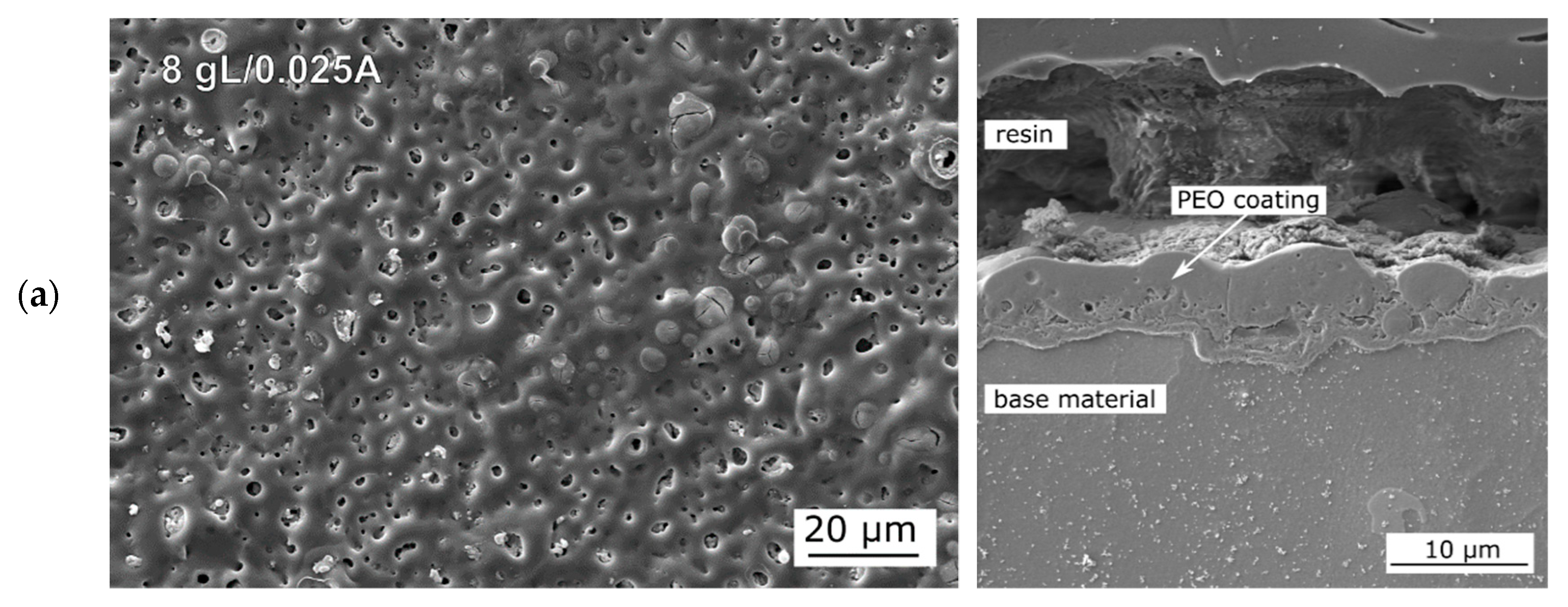
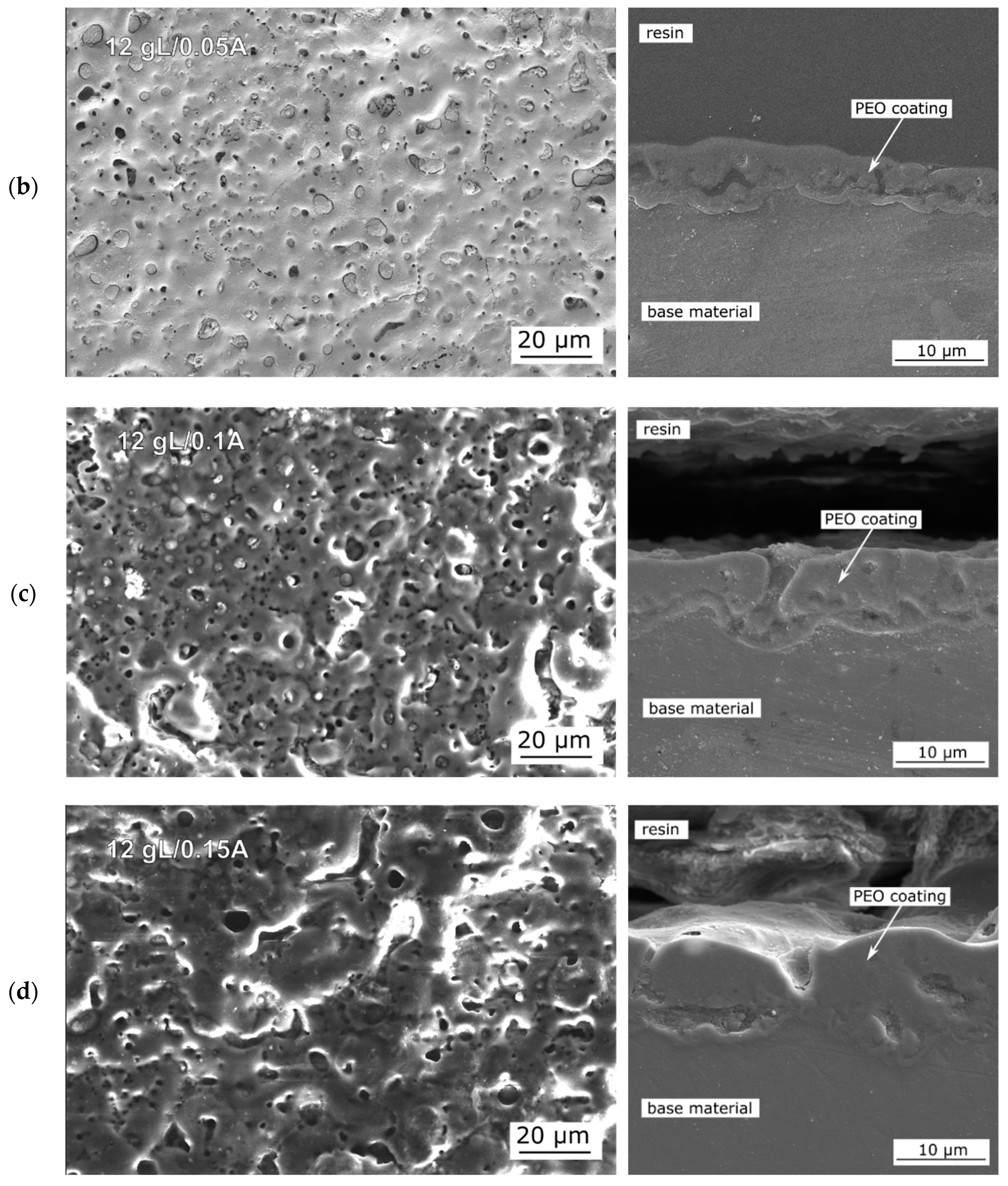
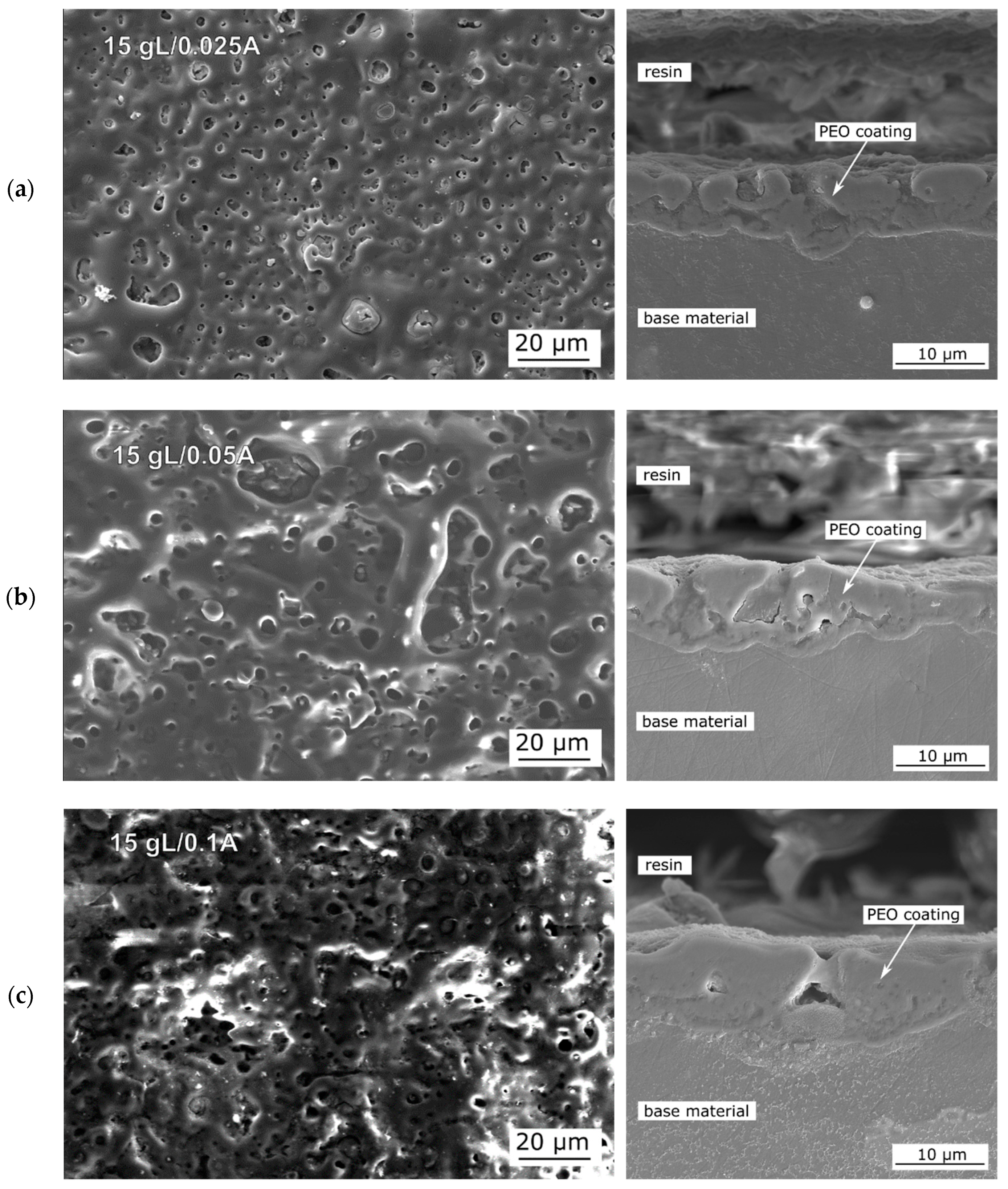
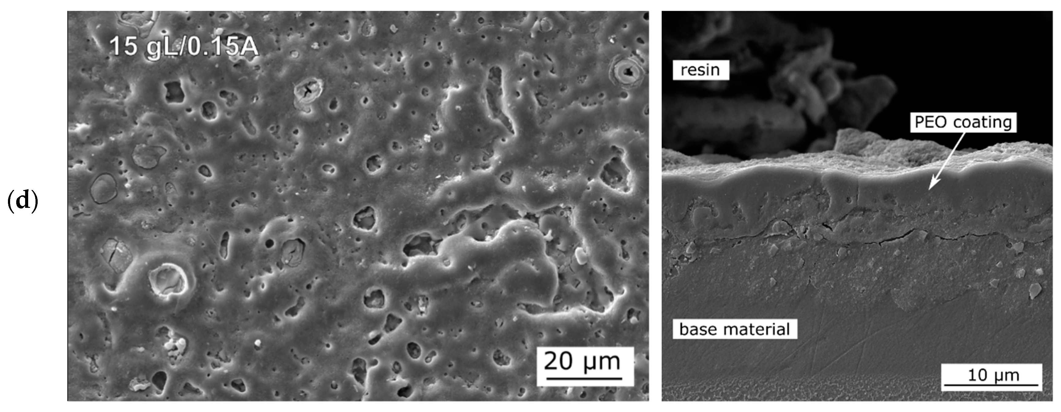
The aim of the study has been to optimize the preparation process of PEO coatings and to study the effect of processing parameters on surface properties of magnesium alloy AZ31. According to the SEM images of PEO coatings (Figure 3, Figure 4, Figure 5 and 
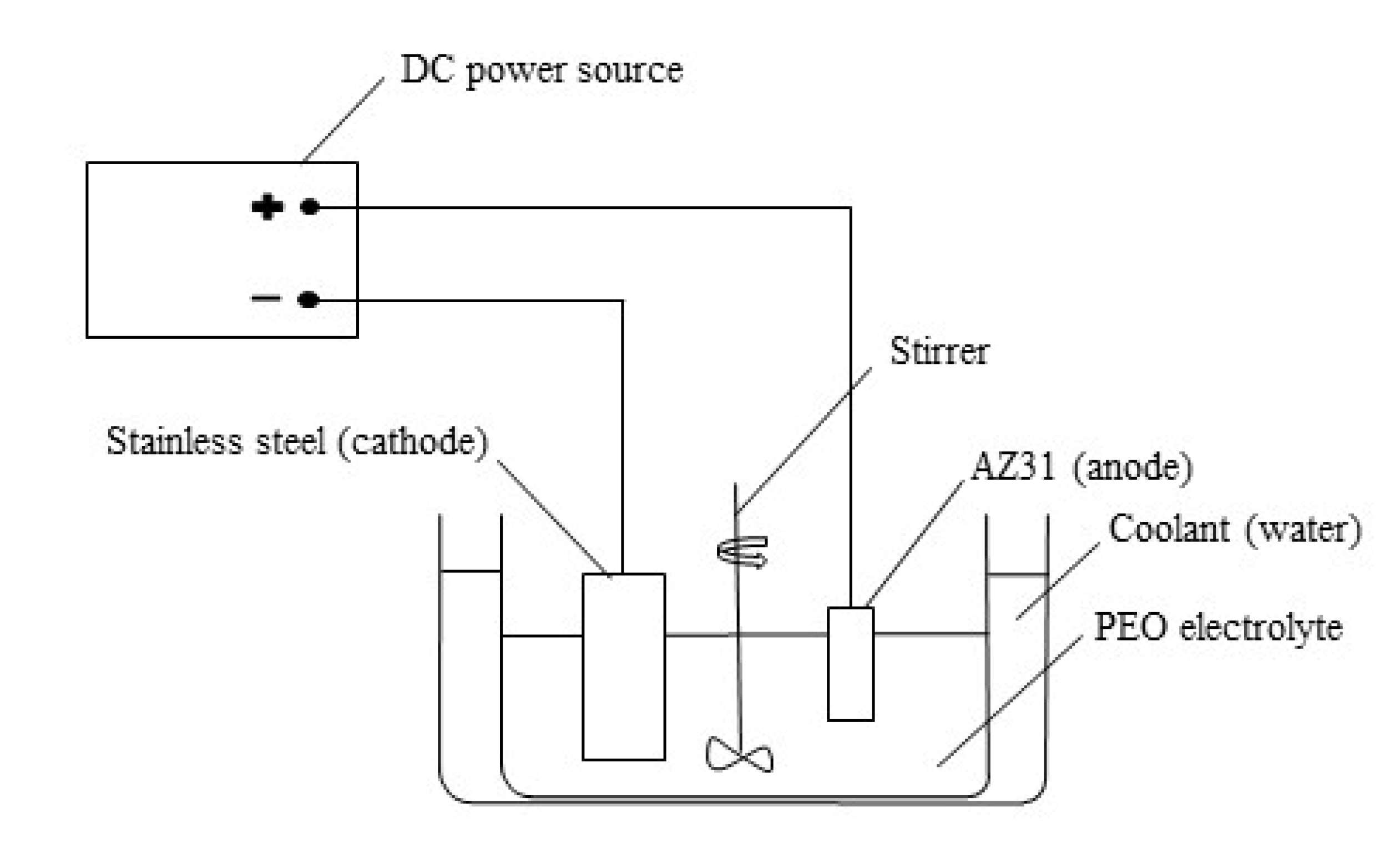
Figure 6), it is clearly visible that all of the combinations of electrolytes and current densities have resulted in porous structures and with the presence of microcracks. These features are connected with the nature of PEO process. At the beginning of PEO process, with constant applied current, voltage and resistance increase with the increasing thickness of the coating. After reaching critical voltage, breakdown of the coating takes place, and discharges start to occur on the surface. The temperature of discharges is high enough (typically thousands of centigrade degrees) to melt already created layer of oxides. Melted oxide flux flow out similarly to the “lava” effect observed in volcanic eruptions. This process is repeated several times, and coating gradually increases its thickness [49,50,51]. Places through which the discharges responsible for the distribution of melted flux passed the oxide layer represent pores when the melted flux is cooled down. Another origin of pores can be explained by entrapped gas bubbles that have been continuously evolved during the PEO process. Microcracks within PEO coating are consequences of internal stresses created when melted oxides are in contact with cold electrolyte. Cross section morphologies reveal that all of the prepared coatings contains sublayers, which determine mechanical and electrochemical properties of PEO coatings [52,53].
The effect of phosphorus content and applied current density on the quality of PEO coatings has been studied. According to the research of [36,54], these two factors have critically affected electrochemical behavior and protective function of PEO coatings. For better quantification of the effect of prepared PEO coatings on corrosion resistance of AZ31 Mg alloy reference surface grounded by an emery paper p1000 has been examined as well. Variation of Rp values of non-treated AZ31 (Table 7) measured in 0.1 M NaCl shows corrosion behavior typical for magnesium alloy [55]. The reaction between Mg substrate and chloride containing solution has led to the creation of corrosion products mainly based on a mixture of Mg(OH)2, MgO and MgCl2. The thickness of corrosion products (CP) has increased and has become more compact as the corrosion reactions have continued resulting in increasing Rp. It is well known that the mentioned CP of Mg are porous and contain cracks. CP based on Mg(OH)2 and MgO are unstable in neutral pH and are able to dissolute in such conditions. Moreover, chloride ions are able to increase local conductivity, penetrate through these defects towards Mg substrate and disrupt the partially protective layer of CP [56]. These features are together responsible for decrease of Rp observed and continued after 48 h of exposure (Figure 7, Table 7). Another explanation of decreasing Rp could be found in reaching the critical weight of CP and consequent partial detachment from the surface [57]. Therefore, thickness of CP has decreased, and magnesium substrate could be locally exposed to the environment [55].
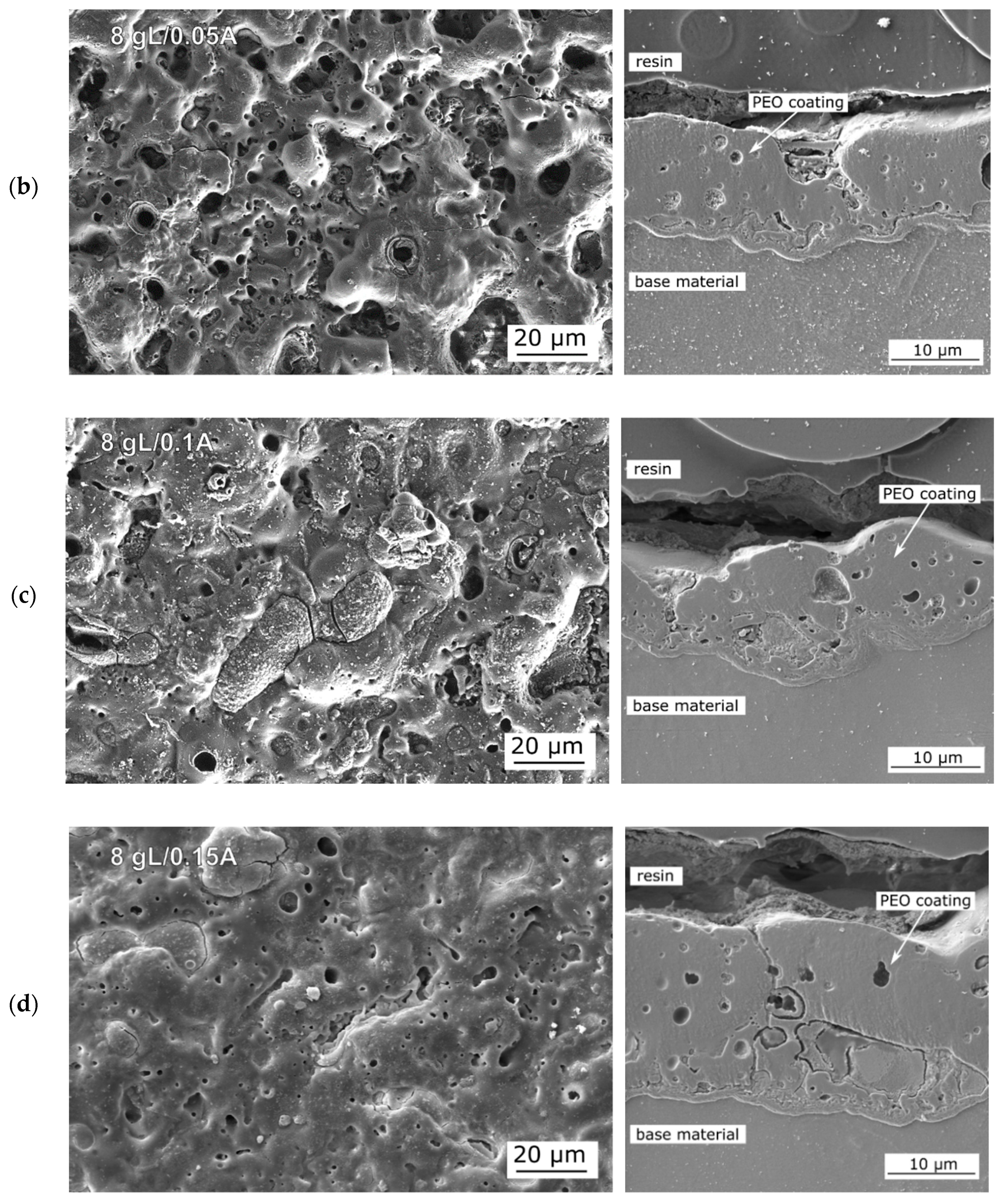
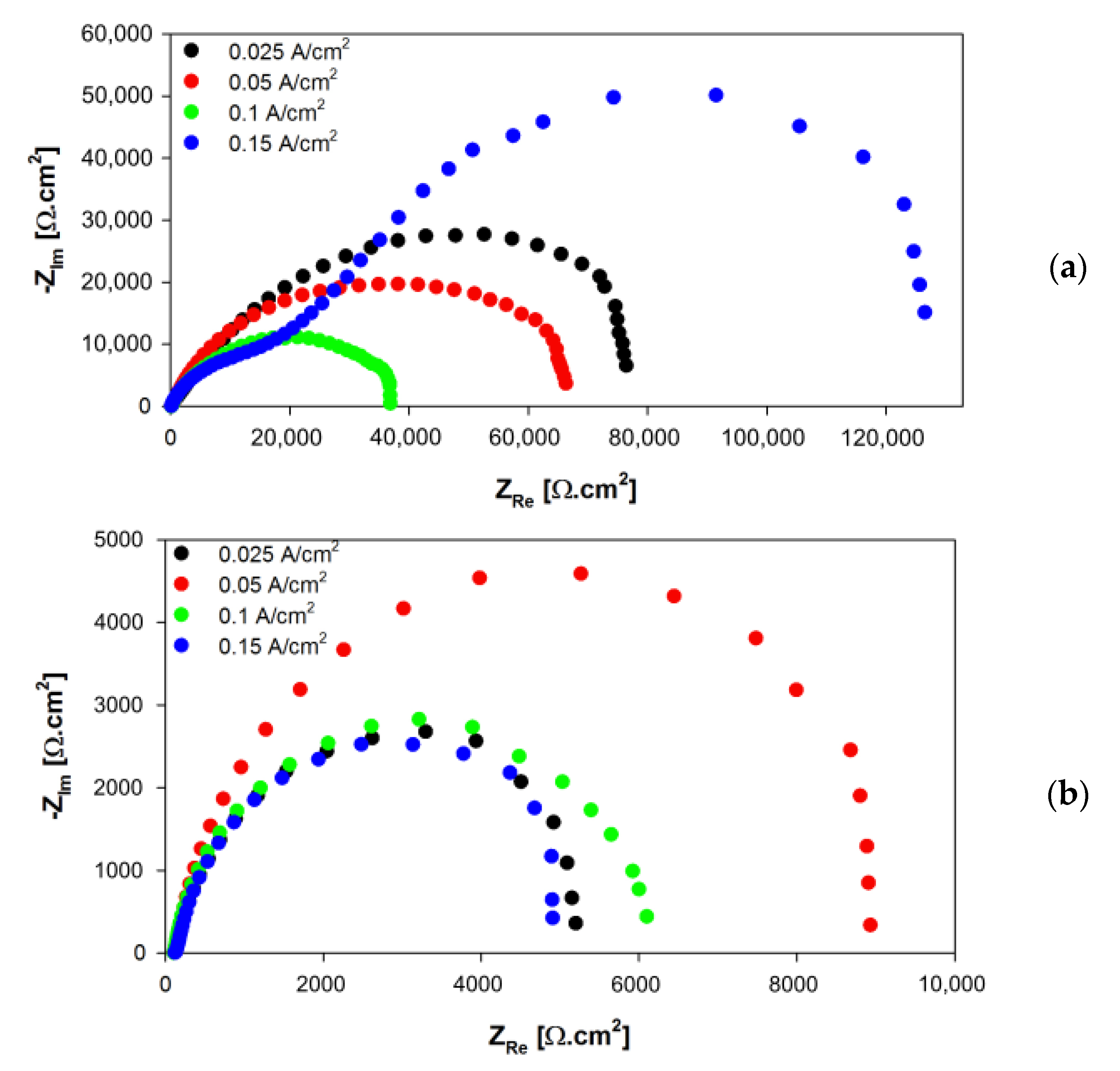
PEO coatings prepared in the electrolyte with the addition of 8 g/L of Na3PO4·12H2O have shown a trend of decreasing porosity with increasing applied current density. On the other hand, the diameter of the pores has increased when a higher current has been used [38]. This phenomenon could be explained by the amount of energy applied to the sample. The higher applied current has led to the higher voltage reached during the PEO process. Higher energy input has been followed by more intense and bigger discharges on the surface, which has led to an increased amount of molten material responsible for the creation of the coating. Such manner has caused accelerated growth of the coatings, which has been reflected by the measured thickness of the coatings and their roughness parameters (Table 3) as well. These findings are in good agreement with research published by [
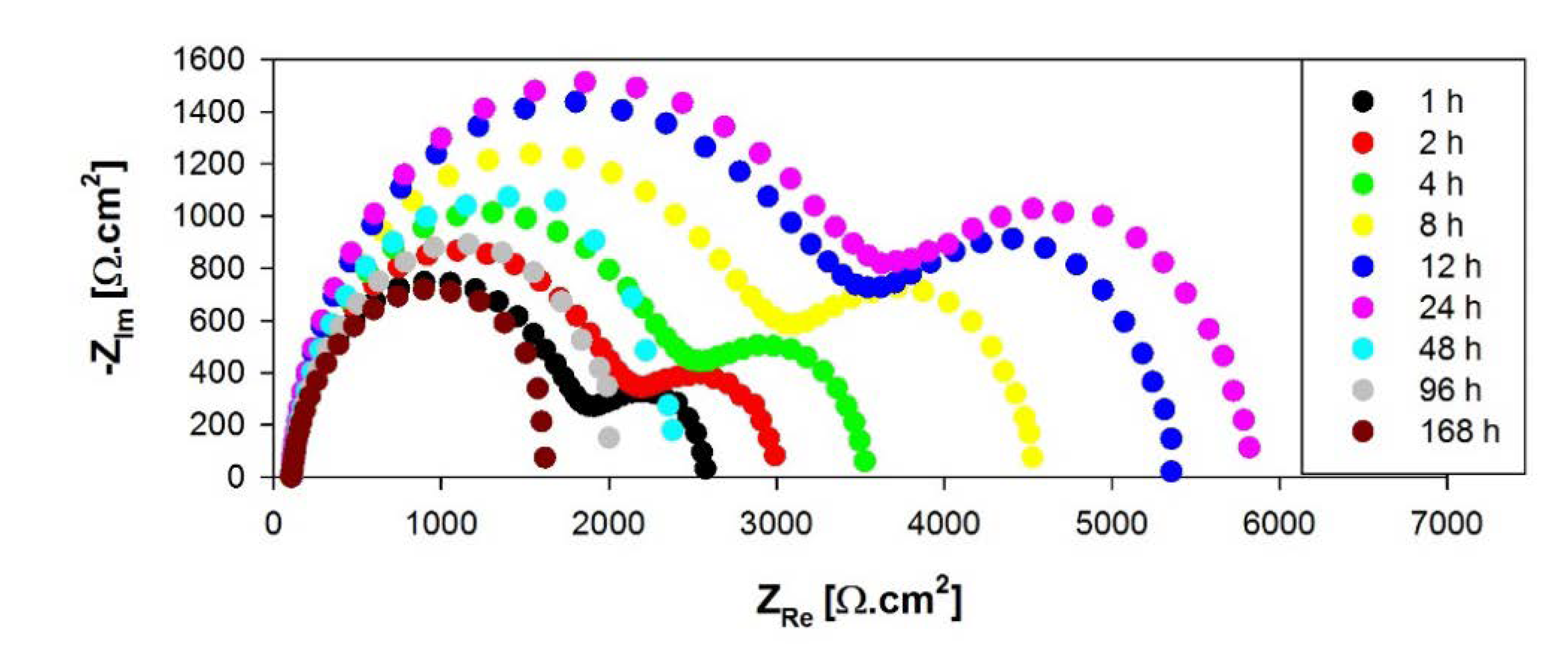
54], where authors have applied PEO on pure magnesium samples and found out that higher applied current has contributed to the creation of more compact and thicker coatings. Results of EIS measurements of all created coatings in electrolyte with the lowest addition of phosphorus have clearly shown the initial trend of decreasing Rp values with increasing time of exposure. When contact of the surface with NaCl electrolyte has been made, the liquid fills pores and cracks of the coatings, saturate and gradually penetrate through these defects towards the magnesium substrate. As time proceeds, delamination of thin parts between the pores takes place together with anodic dissolution of nonstable MgO, both leading to the failure of the whole pieces of the coating and consequent decrease of the coating thickness. This feature is illustrated in Figure 13 showing the PEO coating after 168 h exposure in 0.1 M NaCl. The arrows point to the visible dissolution traces of particular sub-layers proving the statement about the continuous dissolution of the coating, which is affected by aggressive chloride ions. It is also obvious that dissolution has led to the connection of pore areas and, therefore, to the increase of electrochemically active area.
The initial decrease of Rp has been followed by an increase of these values in all four applied current densities. It is believed that the increase in corrosion resistance has been provided by local sealing of damaged areas by corrosion products mainly based on Mg(OH)2, which has resulted in local higher compactness of the coatings [58]. In the terminal stages of exposure, dissolution of the PEO coating has been more intense compared to the sealing process, which dominates previous stages when the initial contact with electrolyte is made. This has been shown by a repeated decrease of Rp values towards the end of EIS measurements. When comparing Rp for each of the four prepared coatings, it can be seen that coating prepared with 0.05 A/cm2 has reached the highest corrosion resistance at the end of the exposure. In the case of 0.025 A/cm2, the failure of coatings has been observed after 48 h, probably due to the insufficient thickness of the coating, which has been indicated by the occurrence of one capacitance loop and significant decrease of Rp (Figure S1). Two remaining coatings (0.1 and 0.15 A/cm2) have exhibited higher thicknesses; however, presence of the larger pores and higher surface roughness have diminished this effect by enlarging the active area providing more intensive attack of the surface leading to delamination of the coating. This feature has been mostly evidenced in the case of 0.15 A/cm2 coating, which has failed after 96 h according to the shape of the Nyquist diagram (Figure S1d). It has to be noted that these degradation mechanisms are applied in a higher or lower degree in each coating examined in this paper.
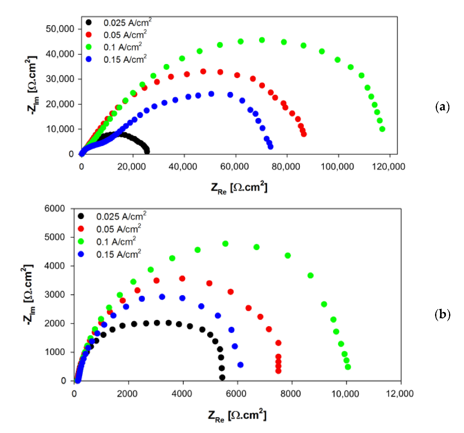
SEM images have shown that increased content of Na3PO4·12H2O to 10 g/L has led to lower porosity of the coatings compared to previous ones. The reason for this behavior could be found in the assumption that increased phosphorus content in the electrolyte has suppressed PEO process that has been documented by lower values of obtained voltages during the preparation of these coatings (Table 2). In consequence, less intensive discharges have been spotted on the surface of the samples. The applied electric field can segregate positive and negative ions to create charged regions. During the PEO coating creation, OH and PO 4 3 ions are consumed for the Mg, Mg(OH)2 and Mg3(PO4)2 creation (see Equations (2)–(4)). The electrical equilibrium disappeared, causing the movement of OH and PO 4 3   ions from the diffusion part of the electrolyte to the vicinity of the metal surface. The resulting rate of ions movement from the diffusive part of the electrolyte is mainly dependent on the permittivity and conductivity of the electrolyte [59,60]. For this reason, the finer size of the sparks observed during the coating creation can relate to the higher rate of the charge transfer provided by the higher concentration of Na3PO4·12H2O compound. Moreover, the finer size of the sparks leads to the formation of the thinner PEO coating formed on the metal surface [61]. These findings contradict the results of authors [36], who have stated that the increased phosphorus content has been a reason for increased porosity of PEO coatings prepared on the surface of AZ31 alloy. However, it has to be noted that electrolyte used for PEO in [36] has contained also silicate ions. As with coatings prepared in 8 g/L Na3PO4·12H2O electrolyte, even here, a continuous decrease of resistance connected with dissolution and degradation of porous coatings has been observed. Moreover, local sealing of defects by corrosion products followed by increasing Rp has taken place [58]. Based on the EIS results obtained by this group of coatings, it can be summarized that the highest corrosion resistance has been provided by using current density of 0.1 A/cm2 (10,688 Ω.cm2). However, the Nyquist diagram at the end of the measurements has been, similarly to other coatings in this group, created by one capacitance loop, which could point to the failure of PEO coating, or it could mean that the remaining coating has not been detected by EIS (Figure S2) [45]. Coatings prepared with lower energy inputs (0.025 and 0.05 A/cm2) have reached lower values of Rp during whole EIS measurements, due to the insufficient thickness of coatings and therefore less intensive barrier effect provided. Despite lower porosity, chloride ions Cl have been able to penetrate through defects in thin coatings and damage/dissolute them to a much higher degree. On the other hand, higher porosity followed by promoted delamination of 0.15 A/cm2 coating has been responsible for lower Rp in the terminal stage of EIS (6110 Ω.cm2) compared to that of 0.1 A/cm2. These factors have played a major role in terms of corrosion resistance by means of the increased electrochemically active area in contact with corrosion environment followed by more severe corrosion attack of the coatings [10,56].
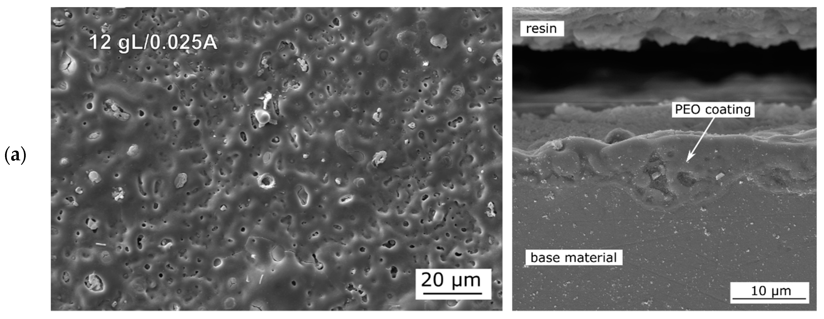
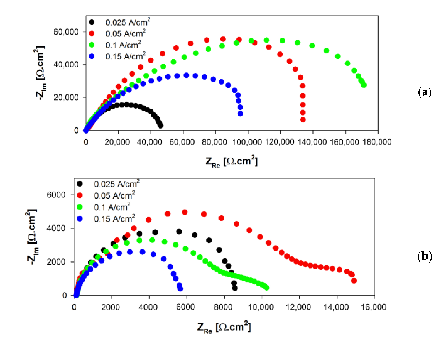
Increased conductivity of electrolyte caused by another increase in phosphorus content in 12 g/L Na3PO4·12H2O electrolyte has been the reason for the lower thickness of the coatings compared to the previous group. On the other hand, these coatings display lower porosity and higher compactness due to the less intensive discharges during preparation. This feature has been expressed by electrochemical characteristics measured at the end of the exposure, where coatings of these group have reached the highest Rp values across all examined concentrations and current densities. The highest corrosion resistance within this group has been measured in the case of 0.05 A/cm2 (14489 Ω.cm2). This value of current density has caused discharges on the surface to be smooth enough to create a structure with small pores as well as provide sufficiently intensive creation of coating to build up a compact barrier between AZ31 substrate and aggressive environment. In spite of the lower porosity of 0.025 A/cm2 coating, energy input has been insufficient to reach steady-state sparking during the 10 min time of the PEO process, which has been reflected by lower corrosion resistance (8699 Ω.cm2). In the case of 0.1 and 0.15 A/cm2 coatings, higher energy input has contributed to more intense discharging effect introducing larger pores to the coatings, and consequently, higher roughness has been obtained. A combination of these factors has been responsible for lower corrosion performance (Table 10) compared to 0.05 A/cm2 coating. Similar results have been presented in a paper by Wang et al., where authors have stated that increased applied current density has led to increased corrosion resistance until reaching a climax, and afterwards, each additional increase in current density has worsened corrosion resistance due to highly promoted porosity [62].
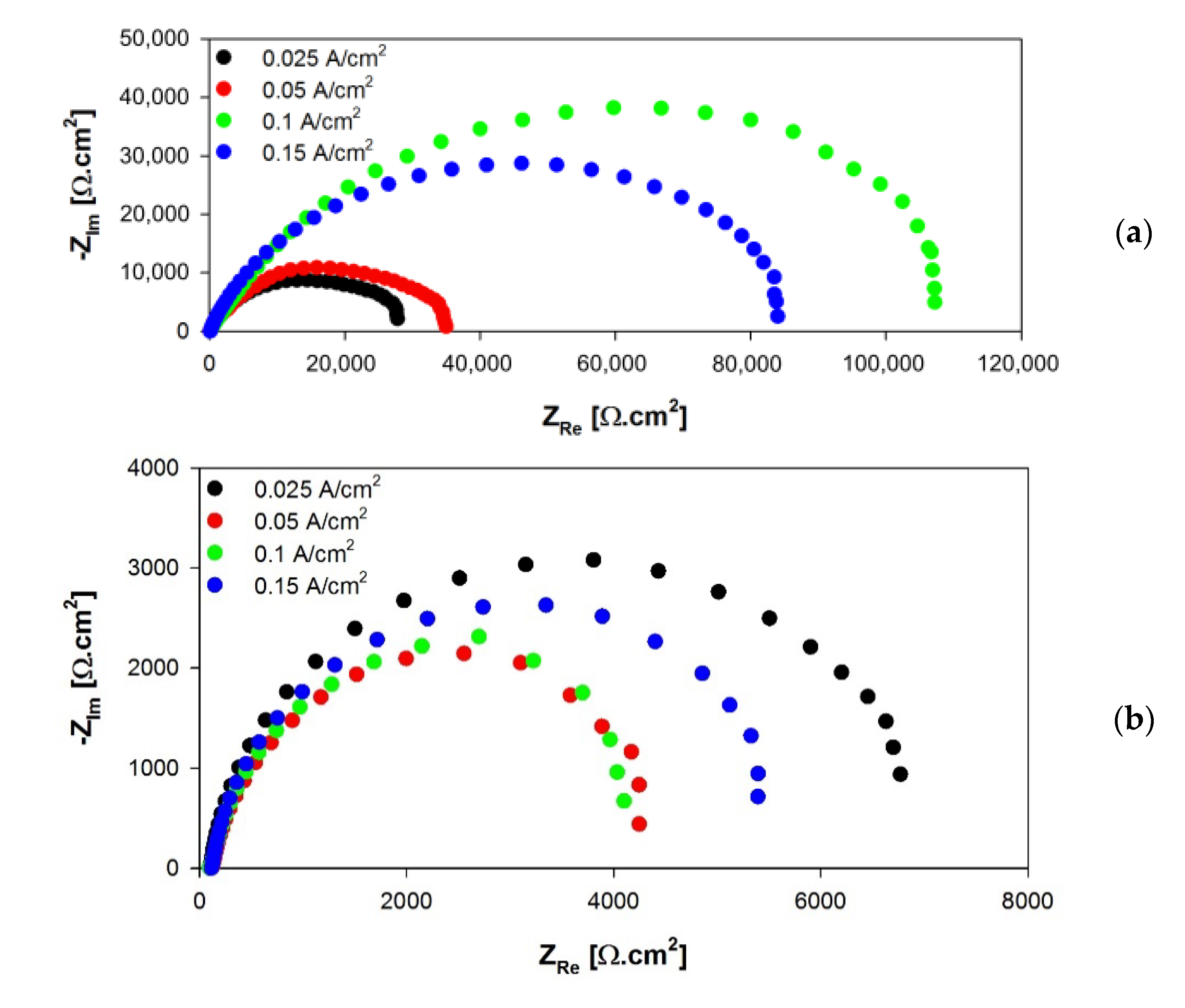
Coatings fabricated in the electrolyte with 15 g/L Na3PO4·12H2O have shown higher porosity and lower thickness compared to those prepared in 12 g/L. This could be related to the lowest recorded voltages during the PEO process as a result of an additional increase in phosphorus content followed by improved electrolyte conductivity (see Table 2). These voltages probably have not been high enough to reach the voltage level required for stable discharging during the PEO process, and oxidation reaction has been strongly limited [26,53]. Increased phosphorus content has been responsible for more extensive creation of Mg3(PO4)2, and MgO/Mg3(PO4)2 ratio has been subsequently lowered. According to [61], MgO is the main constituent responsible for favorable corrosion properties of PEO coatings. On the other hand, increased Mg3(PO4)2 content up to certain level is harmful for corrosion stability of these coatings [61]. Mentioned drawbacks have been reflected in Rp values after 168 h of exposure, where a drop of resistance compared to the previous group of coatings has been observed. Thicknesses and chemical composition of the coatings (Table 6) along with higher electrochemically active area have appeared to be the main reasons for insufficient resistance to aggressive chloride ions contained in the testing electrolyte, and accelerated corrosion degradation has taken place.
Results of performed experiments have pointed to the fact that coatings prepared by the PEO technique using optimized processing parameters could potentially match high requirements and standards for the protection of AZ31 magnesium alloys in chloride containing environments. On the other hand, porosity, although limited, is still an issue for suitable long-term performance of PEO coatings since it is given by the physical nature of the PEO process. Therefore, it is necessary to identify and optimize other processing parameters in order to minimize porosity even more and to extend the lifetime of the bare PEO coatings and those post-treated by one of the sealing treatments as well.

5. Conclusions

In this paper, the optimization of selected processing parameters of PEO treatment has been performed followed by an evaluation of their effect on surface properties with the aim to increase corrosion stability of AZ31 magnesium alloy in chloride containing environment. Based on the obtained results and analysis, the following conclusions are proposed:
  • The applied PEO process of AZ31 magnesium alloy resulted in porous coatings with the appearance of microcracks. The quality of these coatings in terms of porosity, morphology and thickness was strongly dependent on the processing parameters.
  • Results of EIS measurements performed in 0.1 M NaCl showed that all of the prepared PEO coatings improved the mid-term corrosion resistance of AZ31 magnesium alloy from 256% (15 g/L, 0.05 A/cm2) to 1068% (12 g/L, 0.05A/cm2) taking into account the Rp values.
  • By studying the effect of phosphorus content in processing the electrolyte and applied current density on the values of polarization resistance after 168 h of exposure, it was determined that the best corrosion resistance was that of the coating prepared in the electrolyte containing 12 g/L Na3PO4·12H2O, using a current density of 0.05 A/cm2. The Rp measured in case of this coating at the end of exposure was more than 11-times higher (14,489 Ω.cm2) compared to the Rp of ground AZ31 (1240 Ω.cm2).
  • Based on the EDX results, it was concluded that elements with the highest concentration (Mg, O and P) are distributed uniformly thorough the PEO coating.

Supplementary Materials

The following are available online at https://www.mdpi.com/2075-4701/10/11/1521/s1, Figure S1: Nyquist diagrams of PEO coatings prepared in the electrolyte with 8 g/L Na3PO4 with applied current density of 0.025 A/cm2 (a), 0.05 A/cm2 (b), 0.1 A/cm2 (c) and 0.15 A/cm2 (d).; Figure S2: Nyquist diagrams of PEO coatings prepared in the electrolyte with 10 g/L Na3PO4 with applied current density of 0.025 A/cm2 (a), 0.05 A/cm2 (b), 0.1 A/cm2 (c) and 0.15 A/cm2 (d); Figure S3: Nyquist diagrams of PEO coatings prepared in the electrolyte with 12 g/L Na3PO4 with applied current density of 0.025 A/cm2 (a), 0.05 A/cm2 (b), 0.1 A/cm2 (c) and 0.15 A/cm2 (d).; Figure S4: Nyquist diagrams of PEO coatings prepared in the electrolyte with 15 g/L Na3PO4 with applied current density of 0.025 A/cm2 (a), 0.05 A/cm2 (b), 0.1 A/cm2 (c) and 0.15 A/cm2 (d).

Author Contributions

Outline of performed experiments, writing and supervision, B.H. and D.K.; surface treatment, D.K. and M.J. (Michal Jambor); SEM imaging M.J. (Michal Jambor) and M.B.; corrosion testing, J.D. and M.B.; corrosion data analysis, J.B. and J.D.; EDXRF, EDX analysis and SEM image analysis, J.P. and M.J. (Martina Jacková). All authors have read and agreed on the published version of the manuscript.

Funding

The research was financially supported by the Science Grant Agency of the Slovak Republic through project No. 1/0045/17, Grant System of University of Zilina No. 1/2020 (Number of projects: 8003 and 7950) and Operational Program Integrated Infrastructure 2014–2020 of the project: Innovative Solutions for Propulsion, Power and Safety Components of Transport Vehicles, code ITMS 313011V334, co-financed by the European Regional Development Fund. M. Jambor acknowledges the financial support of the Czech Academy of Sciences in the framework of Strategy AV21 “New materials based on metals, ceramics and composites”.

Conflicts of Interest

Authors declare no conflict of interest.

References

  1. Polmear, I.J. Recent developments in light alloys. Mater. Trans. JIM 1996, 37, 12–31. [Google Scholar] [CrossRef] [Green Version]
  2. Song, G.; Atrens, A. Understanding magnesium corrosion. A framework for improved alloy performance. Adv. Eng. Mater. 2003, 5, 837–858. [Google Scholar] [CrossRef]
  3. Esmaily, M.; Svensson, J.E.; Fajardo, S.; Birbilis, N.; Frankel, G.S.; Virtanen, S.; Arrabal, R.; Thomas, S.; Johansson, L.G. Fundamentals and advances in magnesium alloy corrosion. Prog. Mater. Sci. 2017, 89, 92–193. [Google Scholar] [CrossRef]
  4. Gholami-Kermanshahi, M.; Neubert, V.D.; Tavakoli, M.; Pastorek, F.; Smola, B.; Neubert, V. Effect of ECAP Processing on Corrosion Behavior and Mechanical Properties of the ZFW MP Magnesium Alloy as a Biodegradable Implant Material. Adv. Eng. Mater. 2018, 20, 1–12. [Google Scholar] [CrossRef]
  5. Atrens, A.; Song, G.L.; Liu, M.; Shi, Z.; Cao, F.; Dargusch, M.S. Review of recent developments in the field of magnesium corrosion. Adv. Eng. Mater. 2015, 17, 400–453. [Google Scholar] [CrossRef]
  6. Jönsson, M.; Thierry, D.; LeBozec, N. The influence of microstructure on the corrosion behaviour of AZ91D studied by scanning Kelvin probe force microscopy and scanning Kelvin probe. Corros. Sci. 2006, 48, 1193–1208. [Google Scholar] [CrossRef]
  7. Thomas, S.; Medhekar, N.V.; Frankel, G.S.; Birbilis, N. Corrosion mechanism and hydrogen evolution on Mg. Curr. Opin. Solid State Mater. Sci. 2015, 19, 85–94. [Google Scholar] [CrossRef]
  8. Salleh, S.H.; Thomas, S.; Yuwono, J.A.; Venkatesan, K.; Birbilis, N. Enhanced hydrogen evolution on Mg (OH)2 covered Mg surfaces. Electrochim. Acta 2015, 161, 144–152. [Google Scholar] [CrossRef]
  9. Rossrucker, L.; Mayrhofer, K.J.J.; Frankel, G.S.; Birbilis, N. Investigating the Real Time Dissolution of Mg Using Online Analysis by ICP-MS. J. Electrochem. Soc. 2014, 161, C115–C119. [Google Scholar] [CrossRef]
  10. Hadzima, B.; Liptáková, T. Základy Elektrochemickej Korózie Kovov; 1. Vyd.; Žilinská Univerzita: Žilina, Slovakia, 2008; ISBN 8080708762. [Google Scholar]
  11. Pan, F.; Yang, M.; Chen, X. A Review on Casting Magnesium Alloys: Modification of Commercial Alloys and Development of New Alloys. J. Mater. Sci. Technol. 2016, 32, 1211–1221. [Google Scholar] [CrossRef]
  12. Gandel, D.S.; Easton, M.A.; Gibson, M.A.; Abbott, T.; Birbilis, N. The influence of zirconium additions on the corrosion of magnesium. Corros. Sci. 2014, 81, 27–35. [Google Scholar] [CrossRef]
  13. Xu, W.; Birbilis, N.; Sha, G.; Wang, Y.; Daniels, J.E.; Xiao, Y.; Ferry, M. A high-specific-strength and corrosion-resistant magnesium alloy. Nat. Mater. 2015, 14, 1229–1235. [Google Scholar] [CrossRef] [PubMed]
  14. Li, R.; Pan, F.; Jiang, B.; Dong, H.; Yang, Q. Effect of Li addition on the mechanical behavior and texture of the as-extruded AZ31 magnesium alloy. Mater. Sci. Eng. A 2013, 562, 33–38. [Google Scholar] [CrossRef]
  15. You, S.; Huang, Y.; Kainer, K.U.; Hort, N. Recent research and developments on wrought magnesium alloys. J. Magnes. Alloy. 2017. [Google Scholar] [CrossRef]
  16. Czerwinski, F. Magnesium Alloys—Design, Processing and Properties; InTech: Rijeka, Croatia, 2011; ISBN 9789533075204. [Google Scholar]
  17. Li, Z.; Wang, Q.; Luo, A.A.; Peng, L.; Zhang, P. Fatigue behavior and life prediction of cast magnesium alloys. Mater. Sci. Eng. A 2015, 647, 113–126. [Google Scholar] [CrossRef]
  18. Williams, G.; Ap Llwyd Dafydd, H.; Subramanian, R.; McMurray, H.N. The influence of chloride ion concentration on passivity breakdown in magnesium. Corrosion 2017, 73, 471–481. [Google Scholar] [CrossRef] [Green Version]
  19. Fintová, S.; Kunz, L. Fatigue properties of magnesium alloy AZ91 processed by severe plastic deformation. J. Mech. Behav. Biomed. Mater. 2015, 42, 219–228. [Google Scholar] [CrossRef]
  20. Wang, X.; Juan, Y.G.; Ouyang, Y.J.; He, X.M.; Zhang, J.; Ye, L.Y. One-step pickling-activation before magnesium alloy plating. Trans. Nonferr. Met. Soc. China 2009, 19, 504–510. [Google Scholar] [CrossRef]
  21. Czerwinski, F. Magnesium Alloys—Corrosion and Surface Treatments; InTechOpen: London, UK, 2012; ISBN 9789533079721. [Google Scholar]
  22. Drábiková, J.; Fintová, S.; Ptáček, P.; Kuběna, I.; Březina, M.; Wasserbauer, J.; Doležal, P.; Pastorek, F. Structure and growth kinetic of unconventional fluoride conversion coating prepared on wrought AZ61 magnesium alloy. Surf. Coat. Technol. 2020, 399, 126101. [Google Scholar] [CrossRef]
  23. Ji, R.; Ma, M.; He, Y.; Liu, C.; Fang, T.; Zhang, Z.; Wang, Y.; He, Y.; Wu, J. Improved corrosion resistance of Al2O3 ceramic coatings on AZ31 magnesium alloy fabricated through cathode plasma electrolytic deposition combined with surface pore-sealing treatment. Ceram. Int. 2018, 44, 15192–15199. [Google Scholar] [CrossRef]
  24. Zhou, H.; Li, J.; Li, J.; Ruan, Q.; Jin, W.; Yu, Z.; Li, W.; Chu, P.K. Calcium phosphate coating on biomedical WE43 magnesium alloy pretreated with a magnesium phosphate layer for corrosion protection. Surf. Coat. Technol. 2020, 401, 126248. [Google Scholar] [CrossRef]
  25. Kajánek, D.; Pastorek, F.; Fintová, S.; Bača, A. Study of Corrosion Behavior of Dicalcium Phosphate-dihydrate (DCPD) Coating Prepared by Large Amplitude Sinusoidal Voltammetry (LASV) Technique on ZW3 Magnesium Alloy. Procedia Eng. 2017, 192, 399–403. [Google Scholar] [CrossRef]
  26. Barati Darband, G.; Aliofkhazraei, M.; Hamghalam, P.; Valizade, N. Plasma electrolytic oxidation of magnesium and its alloys: Mechanism, properties and applications. J. Magnes. Alloy. 2017, 5, 74–132. [Google Scholar] [CrossRef]
  27. Rakoch, A.G.; Monakhova, E.P.; Khabibullina, Z.V.; Serdechnova, M.; Blawert, C.; Zheludkevich, M.L.; Gladkova, A.A. Plasma electrolytic oxidation of AZ31 and AZ91 magnesium alloys: Comparison of coatings formation mechanism. J. Magnes. Alloy. 2020, 8, 587–600. [Google Scholar] [CrossRef]
  28. Han, H.; Wang, R.; Wu, Y.; Zhang, X.; Wang, D.; Yang, Z.; Su, Y.; Shen, D.; Nash, P. An investigation of plasma electrolytic oxidation coatings on crevice surface of AZ31 magnesium alloy. J. Alloys Compd. 2019, 811. [Google Scholar] [CrossRef]
  29. Kajánek, D.; Hadzima, B.; Buhagiar, J.; Wasserbauer, J.; Jacková, M. Corrosion degradation of AZ31 magnesium alloy coated by plasma electrolytic oxidation. Transp. Res. Procedia 2019, 40, 51–58. [Google Scholar] [CrossRef]
  30. Tu, W.; Zhu, Z.; Zhuang, X.; Cheng, Y.; Skeldon, P. Effect of frequency on black coating formation on AZ31 magnesium alloy by plasma electrolytic oxidation in aluminate-tungstate electrolyte. Surf. Coat. Technol. 2019, 372, 34–44. [Google Scholar] [CrossRef]
  31. Tseluikin, V.N. On the Structure and Properties of Composite Electrochemical Coatings. A Review. Prot. Met. Phys. Chem. Surf. 2016, 52, 254–266. [Google Scholar] [CrossRef]
  32. Curran, J.A.; Clyne, T.W. Porosity in plasma electrolytic oxide coatings. Acta Mater. 2006, 54, 1985–1993. [Google Scholar] [CrossRef]
  33. Tsai, D.S.; Chou, C.C. Review of the soft sparking issues in plasma electrolytic oxidation. Metals 2018, 8, 105. [Google Scholar] [CrossRef] [Green Version]
  34. Krishna, L.R.; Poshal, G.; Jyothirmayi, A.; Sundararajan, G. Relative hardness and corrosion behavior of micro arc oxidation coatings deposited on binary and ternary magnesium alloys. Mater. Des. 2015, 77, 6–14. [Google Scholar] [CrossRef]
  35. Ma, Y.; Hu, H.; Northwood, D.; Nie, X. Optimization of the electrolytic plasma oxidation processes for corrosion protection of magnesium alloy AM50 using the Taguchi method. J. Mater. Process. Technol. 2007, 182, 58–64. [Google Scholar] [CrossRef]
  36. Mori, Y.; Koshi, A.; Liao, J.; Asoh, H.; Ono, S. Characteristics and corrosion resistance of plasma electrolytic oxidation coatings on AZ31B Mg alloy formed in phosphate—Silicate mixture electrolytes. Corros. Sci. 2014, 88, 254–262. [Google Scholar] [CrossRef]
  37. Li, Z.; Ren, Q.; Wang, X.; Kuang, Q.; Ji, D.; Yuan, R.; Jing, X. Effect of phosphate additive on the morphology and anti-corrosion performance of plasma electrolytic oxidation coatings on magnesium—Lithium alloy. Corros. Sci. 2019, 157, 295–304. [Google Scholar] [CrossRef]
  38. Kajanek, D.; Hadzima, B.; Brezina, M.; Jackova, M. Effect of applied current density of plasma electrolytic oxidation process on corrosion resistance of AZ31 magnesium alloy. Commun. Sci. Lett. Univ. Zilina 2019, 21, 32–36. [Google Scholar] [CrossRef]
  39. Pastorek, F.; Borko, K.; Fintová, S.; Kajánek, D.; Hadzima, B. Effect of Surface Pretreatment on Quality and Electrochemical Corrosion Properties of Manganese Phosphate on S355J2 HSLA Steel. Coatings 2016, 6, 46. [Google Scholar] [CrossRef] [Green Version]
  40. Joseph Raj, X.; Nishimura, T. Studies on galvanic corrosion of iron–magnesium couple by scanning electrochemical microscopy in 0.1 M NaCl solution. J. Ind. Eng. Chem. 2016, 41, 141–150. [Google Scholar] [CrossRef]
  41. Kuchariková, L.; Liptáková, T.; Tillová, E.; Kajánek, D.; Schmidová, E. Role of chemical composition in corrosion of aluminum alloys. Metals 2018, 8, 581. [Google Scholar] [CrossRef] [Green Version]
  42. Cassar, J.; Mallia, B.; Karl, A.; Buhagiar, J. EIS of carburised CoCrMo: Evolution of parameters characterising the metal-electrolyte interface. Surf. Coat. Technol. 2016, 292, 90–98. [Google Scholar] [CrossRef]
  43. Kajánek, D.; Hadzima, B.; Pastorek, F.; Neslušan Jacková, M. Electrochemical impedance spectroscopy characterization of ZW3 magnesium alloy coated by DCPD using LASV deposition technique. Acta Metall. Slovaca 2017, 23, 147–154. [Google Scholar] [CrossRef] [Green Version]
  44. Gholami, M.; Mhaede, M.; Pastorek, F.; Altenberger, I.; Hadzima, B.; Wollmann, M.; Wagner, L. Corrosion Behavior and Mechanical Properties of Ultrafine-Grained Pure Copper with Potential as a Biomaterial. Adv. Eng. Mater. 2016, 18, 615–623. [Google Scholar] [CrossRef]
  45. Amirudin, A.; Thieny, D. Application of electrochemical impedance spectroscopy to study the degradation of polymer-coated metals. Prog. Org. Coat. 1995, 26, 1–28. [Google Scholar] [CrossRef]
  46. Gu, Y.; Bandopadhyay, S.; Chen, C.F.; Ning, C.; Guo, Y. Long-term corrosion inhibition mechanism of microarc oxidation coated AZ31 Mg alloys for biomedical applications. Mater. Des. 2013, 46, 66–75. [Google Scholar] [CrossRef]
  47. Galicia, G.; Pébère, N.; Tribollet, B.; Vivier, V. Local and global electrochemical impedances applied to the corrosion behaviour of an AZ91 magnesium alloy. Corros. Sci. 2009, 51, 1789–1794. [Google Scholar] [CrossRef] [Green Version]
  48. Hadzima, B.; Pastorek, F.; Borko, K.; Fintová, S.; Kajánek, D.; Bagherifard, S.; Gholami-Kermanshahi, M.; Trško, L.; Pastorková, J.; Brezina, J. Effect of phosphating time on protection properties of hurealite coating: Differences between ground and shot peened HSLA steel surface. Surf. Coat. Technol. 2019, 375, 608–620. [Google Scholar] [CrossRef]
  49. Chang, L. Growth regularity of ceramic coating on magnesium alloy by plasma electrolytic oxidation. J. Alloys Compd. 2009, 468, 462–465. [Google Scholar] [CrossRef]
  50. Hussein, R.O.; Nie, X.; Northwood, D.O. Plasma electrolytic oxidation (PEO) coatings on Mg-alloys for improved wear and corrosion resistance. Surf. Contact Mech. Incl. Tribol. XII 2015, 1, 163–176. [Google Scholar] [CrossRef] [Green Version]
  51. Yerokhin, A.L.; Nie, X.; Leyland, A.; Matthews, A.; Dowey, S.J. Plasma electrolysis for surface engineering. Surf. Coat. Technol. 1999, 122, 73–93. [Google Scholar] [CrossRef]
  52. Tang, M.; Feng, Z.; Li, G.; Zhang, Z.; Zhang, R. High-corrosion resistance of the microarc oxidation coatings on magnesium alloy obtained in potassium fluotitanate electrolytes. Surf. Coat. Technol. 2015, 264, 105–113. [Google Scholar] [CrossRef]
  53. Hussein, R.O.; Nie, X.; Northwood, D.O. An investigation of ceramic coating growth mechanisms in plasma electrolytic oxidation (PEO) processing. Electrochim. Acta 2013, 112, 111–119. [Google Scholar] [CrossRef]
  54. Durdu, S.; Usta, M. Characterization and mechanical properties of coatings on magnesium by micro arc oxidation. Appl. Surf. Sci. 2012, 261, 774–782. [Google Scholar] [CrossRef]
  55. Hadzima, B.; Mhaede, M.; Pastorek, F. Electrochemical characteristics of calcium-phosphatized AZ31 magnesium alloy in 0.9% NaCl solution. J. Mater. Sci. Mater. Med. 2014, 25, 1227–1237. [Google Scholar] [CrossRef] [PubMed]
  56. Song, G. Recent progress in corrosion and protection of magnesium alloys. Adv. Eng. Mater. 2005, 7, 563–586. [Google Scholar] [CrossRef]
  57. Bagherifard, S.; Molla, M.F.; Kajanek, D.; Donnini, R.; Hadzima, B.; Guagliano, M. Accelerated biodegradation and improved mechanical performance of pure iron through surface grain refinement. Acta Biomater. 2019, 98, 88–102. [Google Scholar] [CrossRef]
  58. Liang, J.; Srinivasan, P.B.; Blawert, C.; Dietzel, W. Comparison of electrochemical corrosion behaviour of MgO and ZrO2 coatings on AM50 magnesium alloy formed by plasma electrolytic oxidation. Corros. Sci. 2009, 51, 2483–2492. [Google Scholar] [CrossRef] [Green Version]
  59. Persat, A.; Santiago, J.G. An Ohmic model for electrokinetic flows of binary asymmetric electrolytes. Curr. Opin. Colloid Interface Sci. 2016, 24, 52–63. [Google Scholar] [CrossRef]
  60. Bagotsky, V.S. Fundamentals of Electrochemistry, 2nd ed.; John Wiley & Sons: Hoboken, NJ, USA, 2006; ISBN 9780471700586. [Google Scholar]
  61. Ghasemi, A.; Scharnagl, N.; Blawert, C.; Dietzel, W.; Kainer, K.U. Influence of electrolyte constituents on corrosion behaviour of PEO coatings on magnesium alloys. Surf. Eng. 2010, 26, 321–326. [Google Scholar] [CrossRef]
  62. Wang, H.M.; Chen, Z.H.; Li, L.L. Corrosion resistance and microstructure characteristics of plasma electrolytic oxidation coatings formed on AZ31 magnesium alloy. Surf. Eng. 2010, 26, 385–391. [Google Scholar] [CrossRef]
Figure 1. Scheme of plasma electrolytic oxidation (PEO) process.
Metals 10 01521 g001
Figure 2. Equivalent circuits used for the analysis of Nyquist diagrams with one capacitive loop (a) and two capacitive loops (b,c).
Metals 10 01521 g002
Figure 3. Morphology of the PEO coating prepared in the electrolyte with 8 g/L of Na3PO4·12H2O and current density of 0.025 A/cm2 (a), 0.05 A/cm2 (b), 0.1 A/cm2 (c) and 0.15 A/cm2 (d).
Metals 10 01521 g003aMetals 10 01521 g003b
Figure 4. Morphology of the PEO coating prepared in the electrolyte with 10 g/L of Na3PO4·12H2O and current density of 0.025 A/cm2 (a), 0.05 A/cm2 (b), 0.1 A/cm2 (c) and 0.15 A/cm2 (d).
Metals 10 01521 g004aMetals 10 01521 g004b
Figure 5. Morphology of the PEO coating prepared in the electrolyte with 12 g/L of Na3PO4·12H2O and current density of 0.025 A/cm2 (a), 0.05 A/cm2 (b), 0.1 A/cm2 (c) and 0.15 A/cm2 (d).
Metals 10 01521 g005aMetals 10 01521 g005b
Figure 6. Morphology of the PEO coating prepared in the electrolyte with 15 g/L of Na3PO4·12H2O and current density of 0.025 A/cm2 (a), 0.05 A/cm2 (b), 0.1 A/cm2 (c) and 0.15 A/cm2 (d).
Metals 10 01521 g006aMetals 10 01521 g006b
Figure 7. Nyquist diagrams of ground AZ31 measured in 0.1 M NaCl after various exposure times.
Metals 10 01521 g007
Figure 8. Nyquist diagrams of PEO coatings prepared in the electrolyte with 8 g/L Na3PO4 with different applied current densities after 1 h (a) and 168 h (b).
Metals 10 01521 g008
Figure 9. Nyquist diagrams of PEO coatings prepared in the electrolyte with 10 g/L Na3PO4 with different applied current densities after 1 h (a) and 168 h (b).
Metals 10 01521 g009
Figure 10. Nyquist diagrams of PEO coatings prepared in the electrolyte with 12 g/L Na3PO4 with different applied current densities after 1 h (a) and 168 h (b).
Metals 10 01521 g010
Figure 11. Nyquist diagrams of PEO coatings prepared in the electrolyte with 15 g/L Na3PO4 with different applied current densities after 1 h (a) and 168 h (b).
Metals 10 01521 g011
Figure 12. EDX mapping (a), EDX spectra (b) and distribution of Mg (c), O (d) and P (e) of PEO coating fabricated on AZ31 alloy in the electrolyte containing 12 g/L of Na3PO4·12H2O.
Metals 10 01521 g012
Figure 13. PEO coating after 168 h of exposure in 0.1 M NaCl.
Metals 10 01521 g013
Table 1. Chemical composition of AZ31 magnesium alloy.
ElementAlZnMnSiCuMg
wt.%3.320.670.230.1170.003bal.
Table 2. Steady state values of voltage recorded during the PEO process.
8 g/L Na3PO4Current density (A/cm2)0.0250.050.10.15
U (V)439469478487
10 g/L Na3PO4Current density (A/cm2)0.0250.050.10.15
U (V)418449466476
12 g/L Na3PO4Current density (A/cm2)0.0250.050.10.15
U (V)403433451460
15 g/L Na3PO4Current density (A/cm2)0.0250.050.10.15
U (V)301340357415
Table 3. Thickness and roughness parameters of the PEO coatings prepared in the electrolyte with 8 g/L of Na3PO4·12H2O.
Current DensityThickness
[µm]
Roughness [µm]
RaRzRsk
0.025 A/cm27.641.189.630.87
0.05 A/cm213.161.7714.670.251
0.1 A/cm214.321.8114.460.12
0.15 A/cm218.224.3136.061.35
Table 4. Thickness and roughness parameters of the PEO coatings prepared in electrolyte with 10 g/L of Na3PO4·12H2O.
Current densityThickness
[µm]
Roughness [µm]
RaRzRsk
0.025 A/cm27.810.718.050.87
0.05 A/cm210.561.059.270.96
0.1 A/cm210.681.7614.350.62
0.15 A/cm214.852.0917.190.59
Table 5. Thickness and roughness parameters of the PEO coatings prepared in the electrolyte with 12 g/L of Na3PO4·12H2O.
Current densityThickness
[µm]
Roughness [µm]
RaRzRsk
0.025 A/cm27.291.019.670.87
0.05 A/cm28.991.6113.770.38
0.1 A/cm210.741.7915.410.31
0.15 A/cm213.852.0116.31−0.06
Table 6. Thickness and roughness parameters of the PEO coatings prepared in the electrolyte with 15 g/L of Na3PO4·12H2O.
Current DensityThickness
[µm]
Roughness [µm]
RaRzRsk
0.025 A/cm26.920.745.991.08
0.05 A/cm28.351.0710.730.49
0.1 A/cm28.651.6911.960.48
0.15 A/cm29.410.766.380.67
Table 7. Values of Rp for AZ31 measured in 0.1 M NaCl after various exposure times.
Rp (Ω.cm2)1 h2 h4 h8 h12 h24 h48 h96 h168 h
ground AZ312438 ± 1892822 ± 3263389 ± 3614357 ± 1645271 ± 3175614 ± 1102154 ± 951852 ± 1081240 ± 86
Table 8. Values of Rp of PEO coatings prepared in the electrolyte with 8 g/L Na3PO4 with various applied current densities measured in 0.1 M NaCl.
Rp (Ω.cm2)1 h2 h4 h8 h12 h24 h48 h96 h168 h
0.025 A/cm276,821 ± 321218,486 ± 61410,671 ± 2099633 ± 21510,110 ± 20111,005 ± 1574043 ± 875046 ± 1115878 ± 98
0.05 A/cm266,299 ± 154730,322 ± 71612,333 ± 23114,979 ± 31012,545 ± 24916,598 ± 41118,047 ± 43717,637 ± 2999439 ± 122
0.1 A/cm238,243 ± 51041,385 ± 55515,474 ± 27613,321 ± 28815,216 ± 34115,000 ± 29215,875 ± 19214,479 ± 1436012 ± 61
0.15 A/cm2139,285 ± 716396,599 ± 465126,215 ± 65113,674 ± 30518,093 ± 40311,158 ± 1499258 ± 1117731 ± 784740 ± 26
Table 9. Values of Rp of PEO coatings prepared in the electrolyte with 10 g/L Na3PO4 with various applied current densities measured in 0.1 M NaCl.
Rp (Ω.cm2)1 h2 h4 h8 h12 h24 h48 h96 h168 h
0.025 A/cm226,863 ± 50115,297 ± 2697208 ± 1016897 ± 977331 ± 1309215 ± 18410,833 ± 20011,391 ± 1885223 ± 41
0.05 A/cm285,213 ± 308429,312 ± 62722,990 ± 31013,240 ± 20410,423 ± 14616,550 ± 24111,467 ± 1199936 ± 997221 ± 37
0.1 A/cm2116,321 ± 5084111,242 ± 448737,844 ± 71625,958 ± 49027,272 ± 27619,550 ± 11725,638 ± 34215,224 ± 17310,688 ± 145
0.15 A/cm277,681 ± 257969,913 ± 188137,439 ± 66134,303 ± 59725,088 ± 27617,187 ± 22725,939 ± 3009000 ± 866110 ± 61
Table 10. Values of Rp of PEO coatings prepared in the electrolyte with 12 g/L Na3PO4 with various applied current densities measured in 0.1 M NaCl.
Rp (Ω.cm2)1 h2 h4 h8 h12 h24 h48 h96 h168 h
0.025 A/cm248,017 ± 102023,945 ± 26811,598 ± 11715,077 ± 24711,784 ± 13117,981 ± 23613,378 ± 17611,543 ± 1238699 ± 76
0.05 A/cm2133,420 ± 646361,810 ± 177621,540 ± 30721,698 ± 24028,053 ± 34729,297 ± 39928,410 ± 36917,428 ± 16114,489 ± 104
0.1 A/cm2178,991 ± 849369,768 ± 211035,220 ± 62119,958 ± 18916,091 ± 11916,519 ± 204 13,994 ± 17311,492 ± 13410,032 ± 111
0.15 A/cm295,100 ± 317661,979 ± 142824,525 ± 34119,027 ± 27910,780 ± 20612,658 ± 22412,149 ± 18312,908 ± 2305872 ± 69
Table 11. Values of Rp of PEO coatings prepared in the electrolyte with 15 g/L Na3PO4 with various applied current densities measured in 0.1 M NaCl.
Rp (Ω.cm2)1 h2 h4 h8 h12 h24 h48 h96 h168 h
0.025 A/cm226,466 ± 34213,868 ± 21611,975 ± 17111,739 ± 15514,308 ± 24217,391 ± 27518,510 ± 27713,221 ± 1616790 ± 83
0.05 A/cm236,836 ± 41126,551 ± 31720,936 ± 26624,882 ± 31431,806 ± 36822,350 ± 24014,826 ± 1997121 ± 534419 ± 47
0.1 A/cm2108,694 ± 321161,521 ± 151625,328 ± 28517,372 ± 23219,501 ± 15725,016 ± 2165331 ± 814622 ± 514635 ± 62
0.15 A/cm282,771 ± 201143,384 ± 52314,979 ± 20712,023 ± 15711,583 ± 16213,133 ± 20013,377 ± 17613,717 ± 1685640 ± 98
Table 12. Chemical composition of PEO coating fabricated on AZ31 alloy in the electrolyte containing 12 g/L of Na3PO4·12H2O.
ElementsMgOPAlNaCa
at.%30.554.413.30.441.160.2
Publisher’s Note: MDPI stays neutral with regard to jurisdictional claims in published maps and institutional affiliations.

