
Affecting Microstructure and Properties of Additively Manufactured AISI 316L Steel by Rotary Swaging


1
Institute of Physics of Materials, Czech Academy of Sciences, Žižkova 22, 61600 Brno, Czech Republic
2
Faculty of Materials Science and Technology, VŠB–Technical University of Ostrava, 17. listopadu 2172/15, 70800 Ostrava, Czech Republic
*
Author to whom correspondence should be addressed.
Materials 2022, 15(18), 6291; https://doi.org/10.3390/ma15186291
Submission received: 14 July 2022
/
Revised: 21 August 2022
/
Accepted: 7 September 2022
/
Published: 9 September 2022
Abstract
:The presented work focused on the development of the microstructural and mechanical properties of a AISI 316L stainless steel workpiece prepared through additive manufacturing and subsequently processed by hot rotary swaging. In order to characterize the effects of swaging on the structural development, samples were taken for electron microscopy scanning and microhardness measurements were taken after each swaging reduction. The as-built and final swaged pieces were also subjected to tensile testing at room temperature and at 900 °C. The structural analyses showed that the hot swaging introduced a substructural formation; low angle grain boundaries prevailed over high angle ones after each pass. The swaging also imparted an almost complete elimination of the porosity and significant grain size; the average grain area decreased from the original value of 365.5 µm2 to 4.4 µm2 after the final swaging pass. The changes in the texture between the passes were negligible, however, the grain refinement went hand in hand with the microhardness increase (up to almost 300 HV1). The results of the tensile testing confirmed that the mechanical properties of the swaged pieces which improved dramatically and remained favorable up to high temperatures.
1. Introduction
Additive manufacturing (AM), also known as 3D printing, involves numerous alternative production methods suitable to the manufacture of components with challenging shapes, based on a computer-aided design (CAD). Selective laser melting (SLM) is one of the powder bed fusion (PBF) AM processes whereby the metal powder used is melted with a powerful laser and subsequently solidified layer by layer [1,2,3,4]. The PBF process is favorably used for the production of components made from various metallic materials, e.g., Al-based [5], Ti-based [6], and Cu-based alloys [7], and numerous types of steel [2,4]. The different types of steel prepared via AM are materials with versatile applications that can be used to produce highly-resistant final components (e.g., machining tools [8]), as well as to fabricate composite and bimetallic materials [9]. For example, Kim et al. [10] used the PBF process of directed energy deposition (DED) to prepare a functionally graded material combining 316L stainless steel with Inconel 718.
The AM has many advantages, among which the greatest ones are rapid production, as well as the ability to create components of complex geometries and functional prints. However, it also features disadvantages, such as the size limitations of 3D-printed components (primarily determined by the printing chamber dimensions), their surface roughness, and the presence of internal printing defects and voids [11]. Given by the number of influencing factors affecting a 3D-printed workpiece (e.g., conditions of melting, heating, and solidification), the microstructural heterogeneity and the anisotropy of properties occur virtually within every manufactured component. Moreover, the repeated melting/solidification process typically introduces the presence of (high) residual stress, which can cause undesirable deformations in the shape and dimensions of the component, especially when non-homogeneously distributed [12]. Therefore, the post-processing can favorably be included to homogenize the as-built structures [13]. The post-processing usually consists of operations involving heat, such as a heat treatment or hot isostatic pressing. Despite the fact that the heat treatment is able to (favorably) affect structures, as well as to more or less homogenize the distribution of the residual stress, it can have a negative effect on the grain size [14]. Annealing can also introduce an undesirable precipitation and, moreover, it cannot fully eliminate the porosity and the presence of clusters of pores [15]. Therefore, additional post-processing is required to homogenize the as-built structures.
One of the possibilities to reduce (eliminate) the occurrence of printing defects and, simultaneously, to improve the performance of the components produced from SLM-manufactured materials is to combine the AM with technologies of plastic deformation. Several researchers used severe plastic deformation (SPD) methods to improve the structures and performance of as-built materials (e.g., friction stir processing/welding (FSP/FSW) [16,17], high pressure torsion (HPT) [18,19], and equal channel angular pressing (ECAP), and related methods [20,21,22,23]), especially with regards to Al-based SLM-manufactured alloys. Hosseinzadeh et al. [24] reported that when the porosity was eliminated, the grain size significantly decreased, and both ductility and the yield strength increased by more than 50% for an Al-based alloy processed via four ECAP passes. However, the applicability of the SPD methods on an industrial scale is limited given the maximum possible dimensions of usable samples. Nevertheless, other industrially applicable forming technologies can advantageously be used to impart a favorable grain refinement and structural homogenization. For example, hot forging is suitable to reduce the porosity of additively produced preforms, as well as to refine their microstructures. The occurring dynamic of recrystallization and the pressure bonding of cavities result in a significant improvement in the ductility and increase in the ultimate tensile strength. Pruncu et al. [25] documented that hot forging eliminated defects and imparted an enhanced mechanical strength, ductility, and improved isotropy within a 3D-printed steel workpiece, whereas Bambach et al. [26,27] reported that the compressive stress present during the hot forging was favorable to close internal voids and enhance microstructures of the Ti6Al4V alloy prepared via SLM.
Among the industrially applicable methods suitable to produce long bars are the radial shear rolling [28] and rotary swaging [29,30] methods. Radial shear rolling imparts the helicoidal flow to the processed materials, which advantageously enables the substantial reduction in porosity, as well as a significant grain refinement. It has also been shown to increase fatigue resistance of Ti-based alloys via the formation of dynamically polygonised dislocation substructures [31]. Rotary swaging (RS) is an intensive plastic deformation method used (in the industry) to gradually reduce cross-sections and increase the lengths of workpieces. The method is based on the repeated imposition of a severe shear strain into the processed materials in order to enhance their structures and properties. For RS, the deformation tool consists of a set of swaging dies, the acting shape of which can be designed according to the required final product shape [32]. Therefore, the method can advantageously be used to create complicated long, solid or hollow axisymmetric products.
The aim of the presented work was to characterize the effects of rotary swaging performed under hot conditions in the development of microstructural and mechanical properties of a SLM-prepared AISI 316L stainless steel workpiece. A 316L stainless steel was selected as it is a well-known and widely applicable material, e.g., for components used in gas transportation, refineries, chemical and petrochemical plants, constructions, automobiles, nuclear reactors, biomedical engineering, etc. [33,34]. In order to assess the dynamic (sub)structural development, the detailed structural observations and microhardness measurements were performed after each swaging pass. The porosity before swaging and after the final pass was evaluated via X-ray micro-computer tomography (μCT). The final swaged rods were also subjected to tensile testing at room and elevated temperatures.
2. Materials and Methods
The material for the experiment was prepared using the selective laser melting (SLM) method using a Renishaw AM400 3D printer (Renishaw plc., Wootton-under-Edge, UK). The original 316L stainless steel powder (by Renishaw plc., Wootton-under-Edge, UK) featured a particle size ranging from 15 to 45 µm. The powder was melted with a laser with a power of 200 W in an inert Argon atmosphere. The parameters used to build the workpiece were of a layer thickness of 50 μm, a focus size of 70 µm, and a scanning speed of 650 mm·s−1. The SLM workpiece, with the diameter of 30 mm, was built with the longitudinal axis parallel to the building substrate from left to right using the meander printing strategy [35]. Given the orientation of the workpiece in the printing chamber, its cross-section was selected to be hexagonal instead of circular in order to prevent any possible post-print shape deformations due to residual stress. Immediately after printing, the SLM workpiece was subjected to a heat treatment at 900 °C for 15 min to reduce the presence of any residual stress. The 3D-printed and subsequently heat-treated workpiece was considered as the initial SLM sample for the subsequent experimental study.
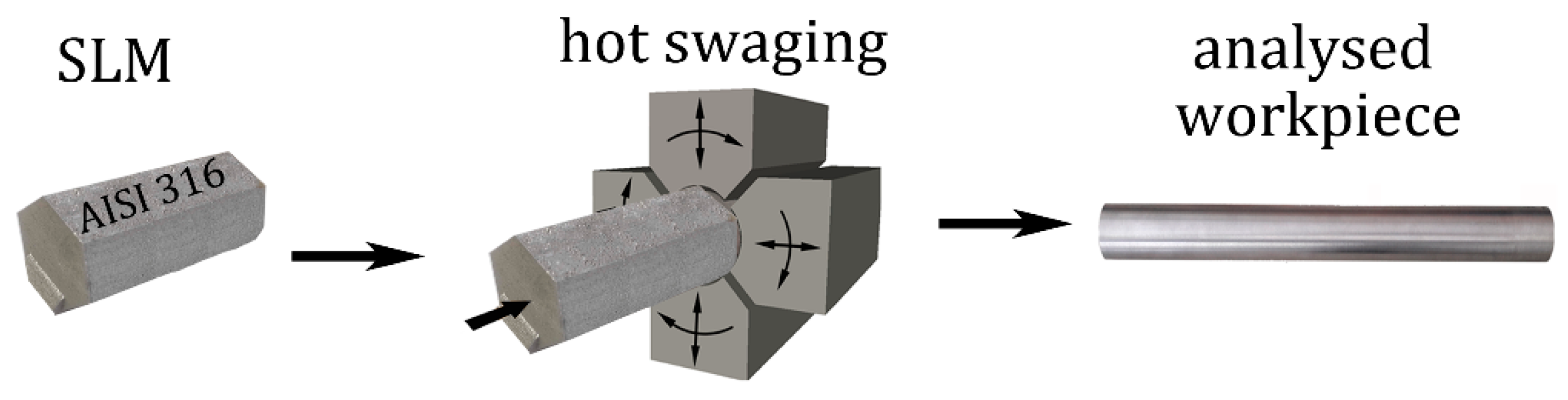
Then, a multi-pass deformation via rotary swaging at the temperature of 900 °C was performed (see Figure 1 for the schematic depiction of the experimental process). The swaging was carried out in four individual swaging passes from the original diameter of 30 mm to the final swaged piece diameter of 10 mm. Prior to the first pass, the edges of the workpiece were chamfered. The swaging ratios after each swaging pass were calculated via Equation (1),
where Si and Sn are cross-section areas at the input and output of the swaging dies, respectively. The swaging ratios for the individually examined samples were 0.35 for sample 1, 0.80 for sample 2, 1.40 for sample 3, and 2.20 for sample 4.
The porosity within the SLM workpiece and sample 4 was examined at room temperature via the X-ray micro-computer tomography (μCT) method (GE phoenix v|tome|x m 300 device with a DXR250 flat panel detector and 300 kV/500 W microfocus X-ray tube, all manufactured by Baker Hughes Digital Solutions GmbH, Hürth, Germany). The measured specimens had the dimensions of 5 × 5 × 5 mm3 and were taken from the axial regions of the SLM-manufactured and swaged pieces (this location was selected as the residual porosity was expected to be the highest within the material volume of the piece, especially for the swaged piece). The exposure time of the detector was 333 ms, the acceleration voltage was 200 kV, and the current of the X-ray tube was 140 μA. The tomographic reconstruction of the scanned data was performed using our own developed evaluation software, while the visualization of the internal void structures was carried out using VG Studio MAX 3 software (version 3.0 by Volume Graphics GmbH, Heidelberg, Germany).
The samples taken after each swaging pass were subjected to structural analyses using the scanning electron microscopy (SEM), in particular, the electron backscatter diffraction (EBSD) method. The observations were made using a Tescan Lyra 3 XMU FEG/SEMxFIB microscope equipped with a Symmetry EBSD detector (Tescan Orsay Holding a.s., Brno, Czech Republic). The samples were mechanically ground on SiC grinding papers and finally electropolished. The EBSD scanning was performed on samples tilted by 70°. For the detailed analyses of the grains, the scans with an area of 100 × 100 µm2 and a scan step of 0.1 µm were acquired, while the larger scans with an area of 200 × 300 µm2 and a scan step of 0.25 µm were made for the texture and grain size analyses. The EBSD analyses were evaluated via Aztec Crystal software (version 2.2, Oxford Instruments, Abingdon, UK). The texture analyses were evaluated with the maximum deviation of 15°, and the limiting value for the low angle grain boundary (LAGB) and high angle grain boundary (HAGB) was 15°.
The microhardness after each pass was measured with the load of 1000 g (HV 1) along two perpendicular diagonals on a cross-sectional sample, using a Zwick Roell machine (Zwick Roell CZ s.r.o., Brno, Czech Republic). The tensile testing of the final swaged pieces at room temperature, also at 900 °C, was performed with the strain rate of 10−3 s−1 using a Zwick/Roell KAPPA DS 50 kN testing machine (Zwick Roell CZ s.r.o., Brno, Czech Republic). For the experiment carried out at room temperature, we used an optical extensometer. During the testing, the testing machine was coupled with a digital image correlation (DIC) system that can digitally measure the longitudinal strain of the tensile specimens by means of two CCD cameras. The surface of each specimen was sprayed with a randomized pattern (painted with white background and scattered with black dots).
3. Results and Discussion
3.1. Analyses of the Grains
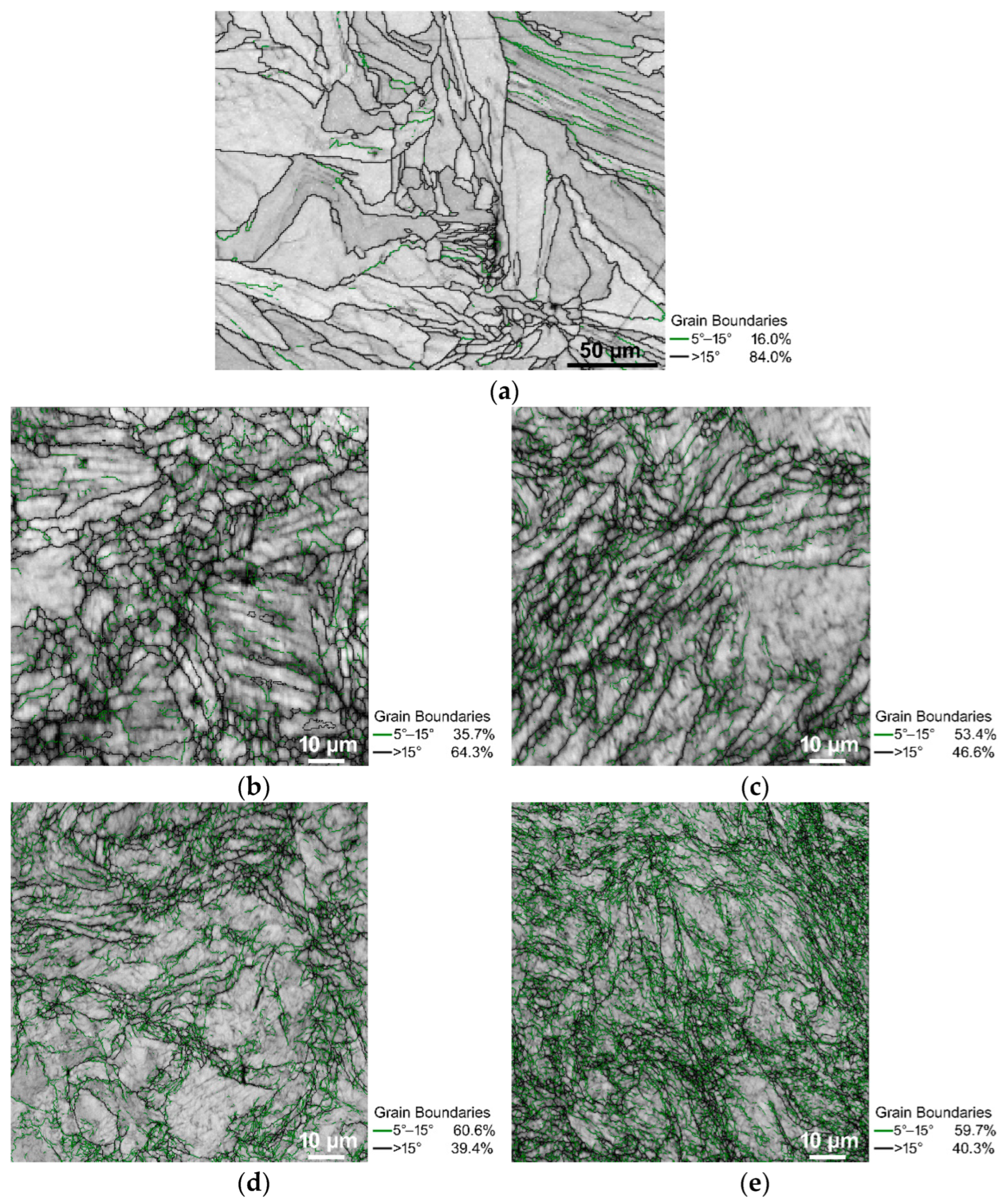
The microstructures of the examined samples can be seen in Figure 2a–e, the band contrast EBSD images with the HAGBs are depicted in black and the LAGBs are depicted in green. The scans were acquired using cross-sectional cuts, at a distance of 0.5 mm below the periphery of each sample as the effect of the imposed shear strain was expected to be the highest in the peripheral regions.
As can be seen, the SLM sample (Figure 2a) consisted mainly of fully developed grains defined with HAGBs. The fraction of the HAGBs then significantly decreased after the first swaging pass (compare 84% HAGBS for the SLM sample with 64.3% HAGBs for sample 1), and then decreased again after the second swaging pass; sample 2 exhibited 46.6% of HAGBs. During the following two passes, the HAGB fractions slightly decreased and remained more or less comparable. In other words, the fractions of the LAGBs increased to approximately 60% for samples 3 and 4 (Figure 2d,e).
The SLM material state consisted mainly of HAGBs (Figure 2a), which was expected as it was an as-printed heat treated material. Following the beginning of the swaging, the fraction of the HAGBs decreased significantly at the expense of the LAGBs, which could be attributed to the development of the substructure. The following swaging pass then caused another decrease in the HAGB fractions; this decrease was comparable with that observed after the first swaging pass (compare the HAGB fractions of 84% for the SLM sample, 64.3% for sample 1, and 46.6% for sample 2—Figure 2a–c). Following the second swaging pass, the structure was saturated and the development of the substructure and the dynamic restoration were equalized by the effect of which the fractions of the HAGBs did not significantly decrease during the continuing swaging (samples 3 and 4 exhibited comparable HAGBs fractions—Figure 2d,e).
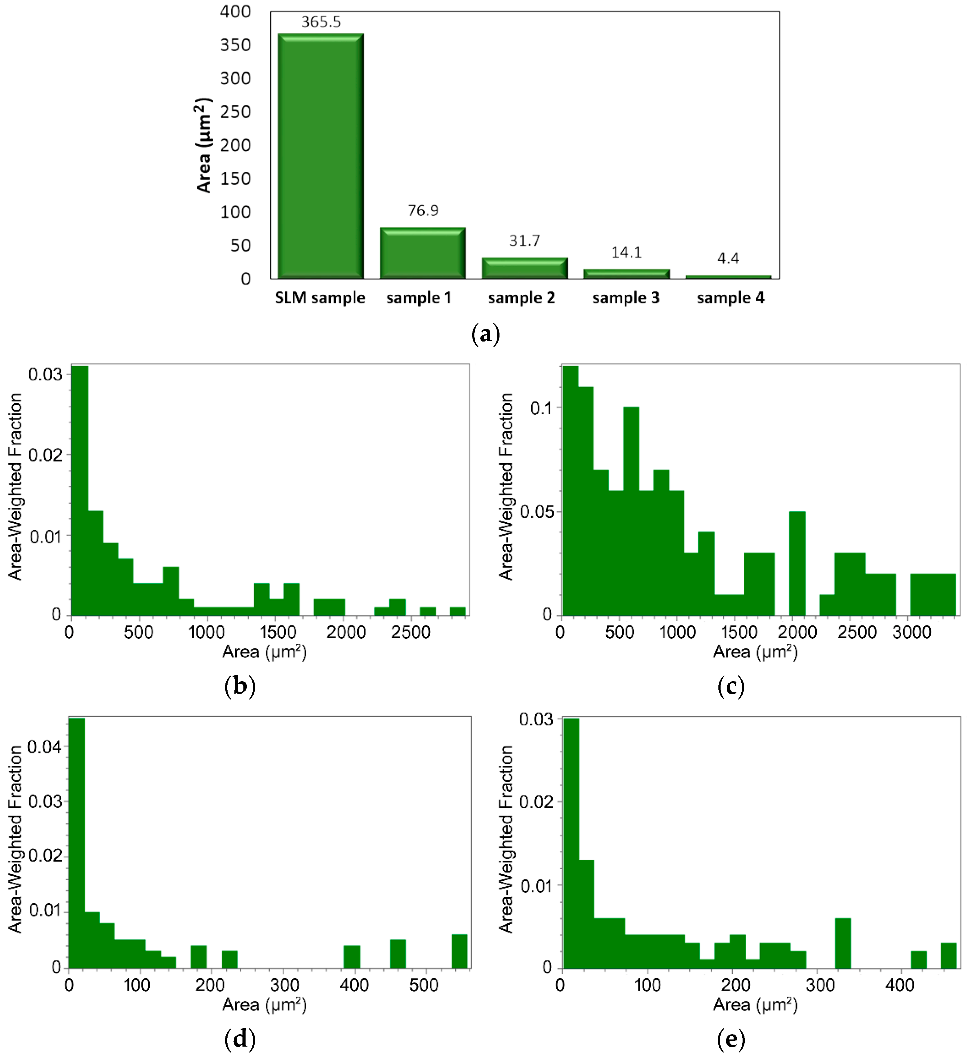
As is evident from Figure 2a–e, especially in the structures of the pieces swaged with a lower reduction, the ratios were mostly bimodal. For this reason, the grain size was evaluated via the average grain area parameter (in μm2), rather than via the average grain diameter (in μm). The results of the grain size analyses for the peripheral areas of all of the examined samples are summarized in Figure 3a showing that the swaging affected the grain size favorably. The average grain area dramatically decreased during the swaging, down to slightly less than 4 μm2 after the final swaging pass. In order to assess the effect of the imposed shear strain on the structural homogenization, the analyses of the peripheral regions were supplemented with analyses of the axial regions for the samples subjected to the first and last swaging passes, i.e., sample 1 and sample 4. As is evident from Figure 3b and c that depict the grain size distributions in the peripheral and axial regions of sample 1 via the area-weighted fractions, the grains in the axial region were evidently larger than in the peripheral region. A similar phenomenon was observed in sample 4 (Figure 3d,e). The continuous substructural development contributed to the significant grain size decrease, as the grains evidently underwent an intense fragmentation. This phenomenon was supported by the mutual effect of the intensive imposed shear strain and elevated temperature [36]. Although the maximum grain areas observed within the structures were significantly higher than the average values, they continuously decreased during the swaging process—from 15,200 μm2 for the SLM sample, to 3240 μm2 for sample 1, 3005 μm2 for sample 2, 2780 μm2 for sample 3, and 580 μm2 for sample 4 (the maximum values acquired from the analyses of the scans were taken in all of the examined areas).
The 3D-printed material consisted of a mixture of large and small grains, i.e., a bimodal structure. Many of the grains were elongated along a single direction (Figure 2a), which gives rise to a hypothesis that this structure developed correspondingly to the heat transfer during the 3D printing. In other words, some of the grains had favorable orientations from the viewpoint of the heat dissipation during the printing, which provided them with advantageous conditions for the (abnormal) growth [37]. However, some of the grains had aggravated conditions for their growth and needed a higher activation energy. This could have been caused by multiple factors, such as the aggravation of grain boundary migration due to obstacles, e.g., voids and printing defects, or rapidly growing adjoining grains resulting in the development of triple junctions with a very low migration ability (similar structural phenomena could have also caused the bimodal grain size distribution within the swaged pieces) [38].
3.2. Texture
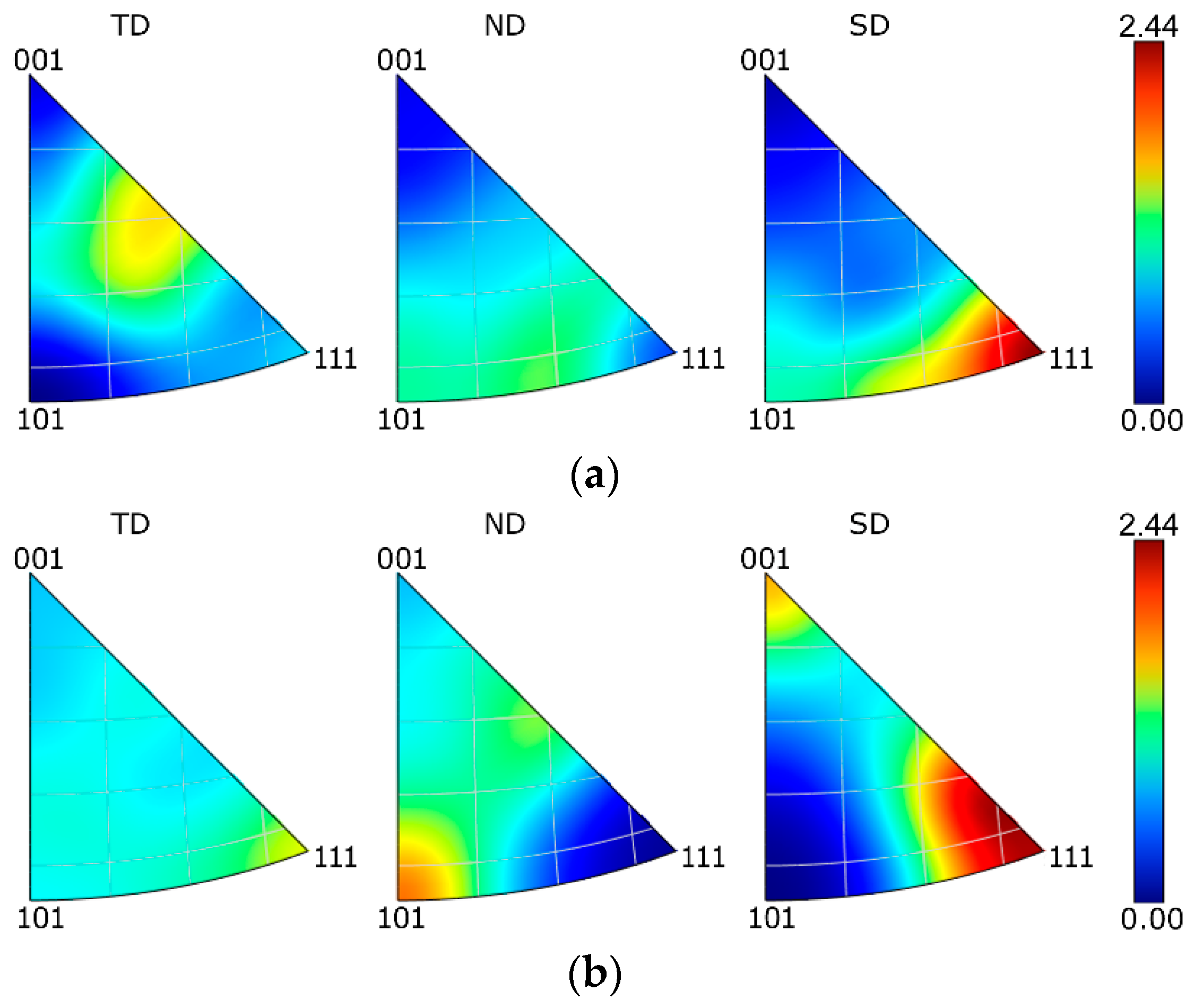
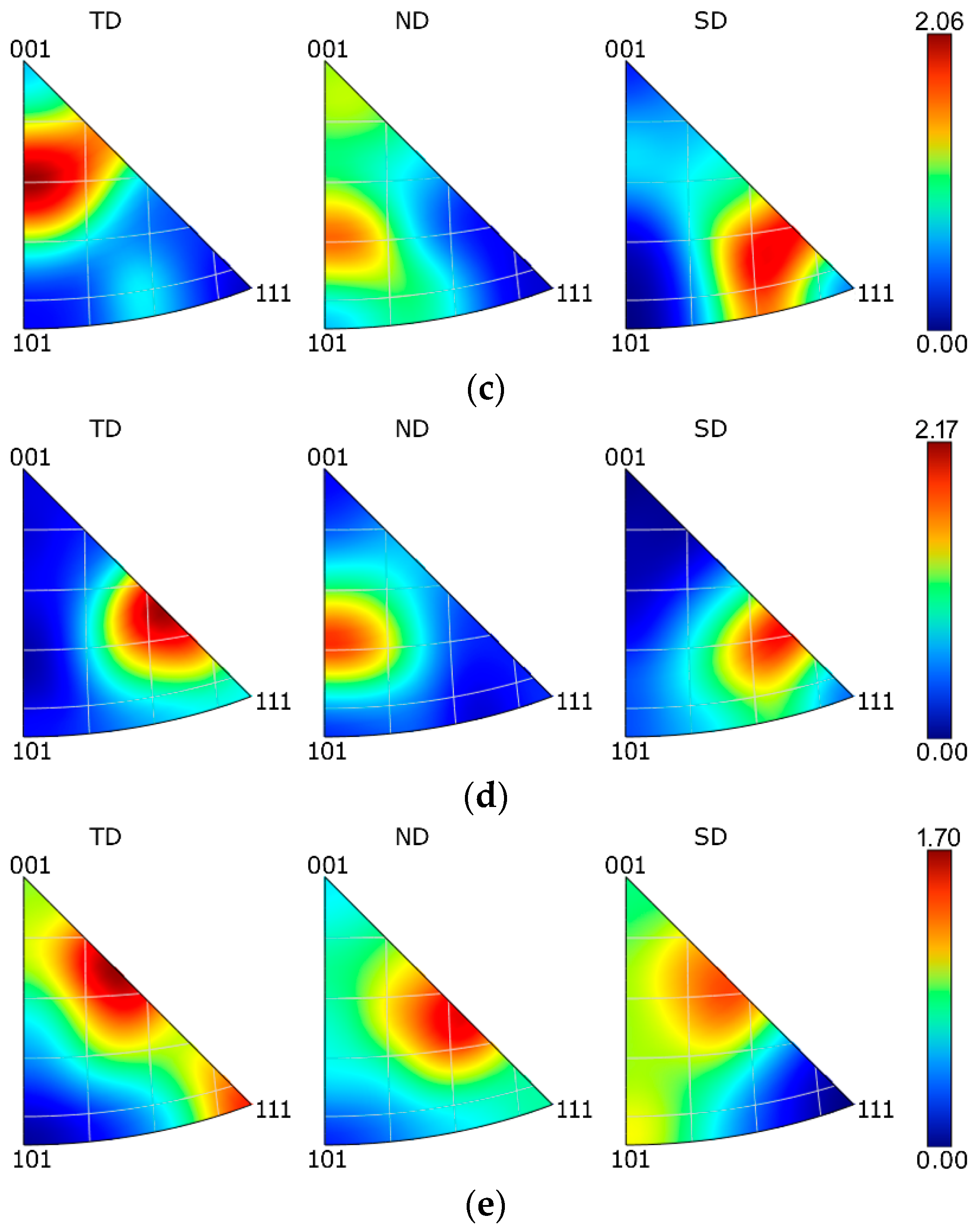
The results of the textural analyses acquired at the peripheral regions of cross-sectional cuts through the swaged bars in the z axis, i.e., the longitudinal sample axis, are depicted via Inverse Pole Figures (IPFs) in Figure 4a–e. The orientations of the crystallites within the SLM sample were more or less random (Figure 4a). The sample featured the tendency to form the <111>||SD preferential texture (with a shift towards the <101>||SD orientation), but its maximum intensity was not very high (slightly higher than two times random). The first swaging pass did not significantly affect the grains’ orientations, as the maximum texture intensity remained more or less unchanged (Figure 4b). However, some of the crystallites exhibited the tendency to form the <001>||SD preferential orientation. Further swaging contributed to texture randomization, as the maximum texture intensity slightly decreased after the second swaging pass (Figure 4c). Furthermore, the tendency to form the <111>||SD texture fiber was reduced and the preferential orientations of the grains shifted by approx. 20° towards the <001>||SD orientation, and 30° towards the <101>||SD orientation for sample 2. Continuing the swaging further contributed to the texture randomization. Both samples 3 and 4 (Figure 4d,e) exhibited a shifting of the <111>||SD preferential texture orientation towards <001>||SD; the highest texture intensity after the final swaging pass was observed approx. 45° between these preferential orientations. The hot swaging process thus contributed to the shifting of the <111>||SD orientation towards the <001>||SD orientation and the decrease in the maximum texture intensity when compared with the SLM sample. The last swaging pass did not introduce any significant texture changes. The IPF images for the TD and SD directions were comparable, although a slight change was observed for the ND direction (Figure 4d,e). The textural analyses thus did not reveal any evident formation of any prevailing ideal texture orientation during the swaging.
3.3. Porosity
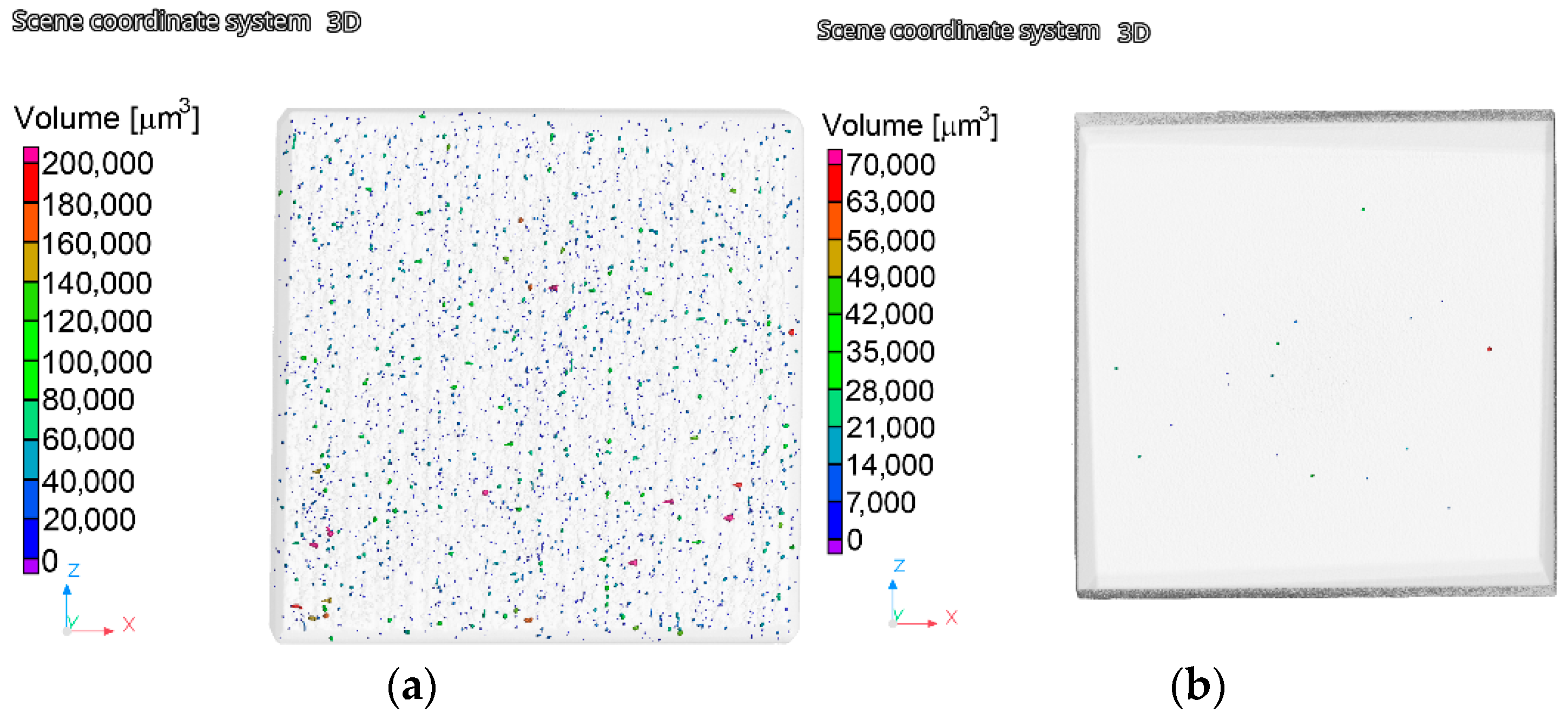
The analyses of the porosity were performed after the SLM manufacturing, as well as after the finalization of the swaging. A visualization of the results was performed along an axial cutting plane superimposed through a cubical scanned sample for each examined material state. As is evident from Figure 5a,b that depict the results for the SLM sample and sample 4, respectively, the effect of the rotary swaging on the elimination of the porosity was highly positive.
In other words, the amount of pores within the swaged sample was negligible when compared to the SLM sample. Nevertheless, not only did the amount of pores decrease dramatically after the swaging, but the two examined samples also differed from the viewpoint of the volume of the pores. Whereas the SLM sample contained relatively huge pores with volumes up to 200,000 μm3, the swaging resulted in a significant decrease in the pore size as the maximum detected pore volume within the sample 4 was ~70,000 μm3. Moreover, the presence of such voluminous pores within the swaged sample was scarce. The overall decrease in porosity—compare the SLM sample with sample 4 —was by ~98%; the pore size had decreased by ~65% after the swaging.
3.4. Mechanical Properties
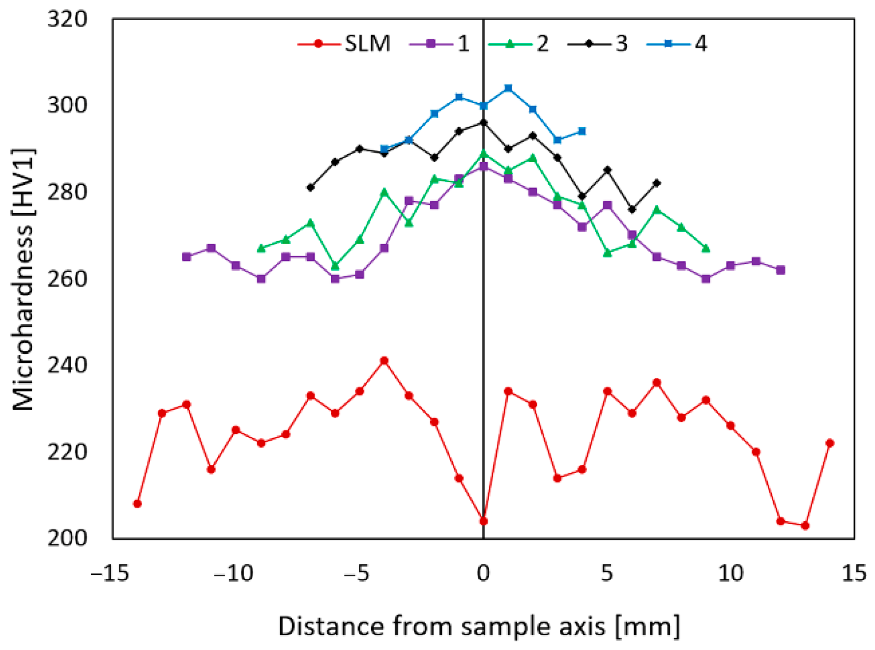
The results of the microhardness measurements performed for each examined material state are summarized in Figure 6 that graphically depicts the distribution of the HV1 values on the diagonals across the cross-sections of the individual samples. The SLM sample evidently exhibited the lowest microhardness out of all of the examined samples (average value of 224 HV1), the values acquired for this material state also featured the highest observed standard deviation of 10.2 with local drops in the locations of the printing defects (pores). The continued swaging then contributed to a gradual microhardness increase up to a final average value of 295 HV1 that was acquired for the final swaged rod, i.e., sample 4. The average HV1 values for sample 1 and sample 2 were comparable (270 HV1 and 272 HV1, respectively), and for sample 3, it reached 286 HV1. The standard deviation decreased to 8.1 for sample 1 and decreased to 7.6 for sample 2, 5.5 for sample 3, and to 4.6 for sample 4.
The fact that the SLM sample featured the lowest acquired microhardness can be attributed to several factors. As this sample was the “raw” as-printed material, it contained numerous printing defects and voids (Figure 5a), which also corresponds to the relatively high HV1 standard deviation value calculated for this sample. Furthermore, the material was heat treated before swaging, which is known to generally reduce the lattice defects and to improve the ductility at the expense of hardness, i.e., strength. Considering all the examined samples, the highest microhardness increase was detected to have occurred during the first swaging pass. This phenomenon could be attributed to the positive effect of swaging on the closing of printing defects and on the development of the substructure, which was initiated with a high intensity due to the high processing temperature and significant imposed shear strain. Further development of the substructure and gradual grains’ fragmentation then contributed to the microhardness increase during the swaging up to the final value of ̴ 300 HV1 acquired for sample 4.
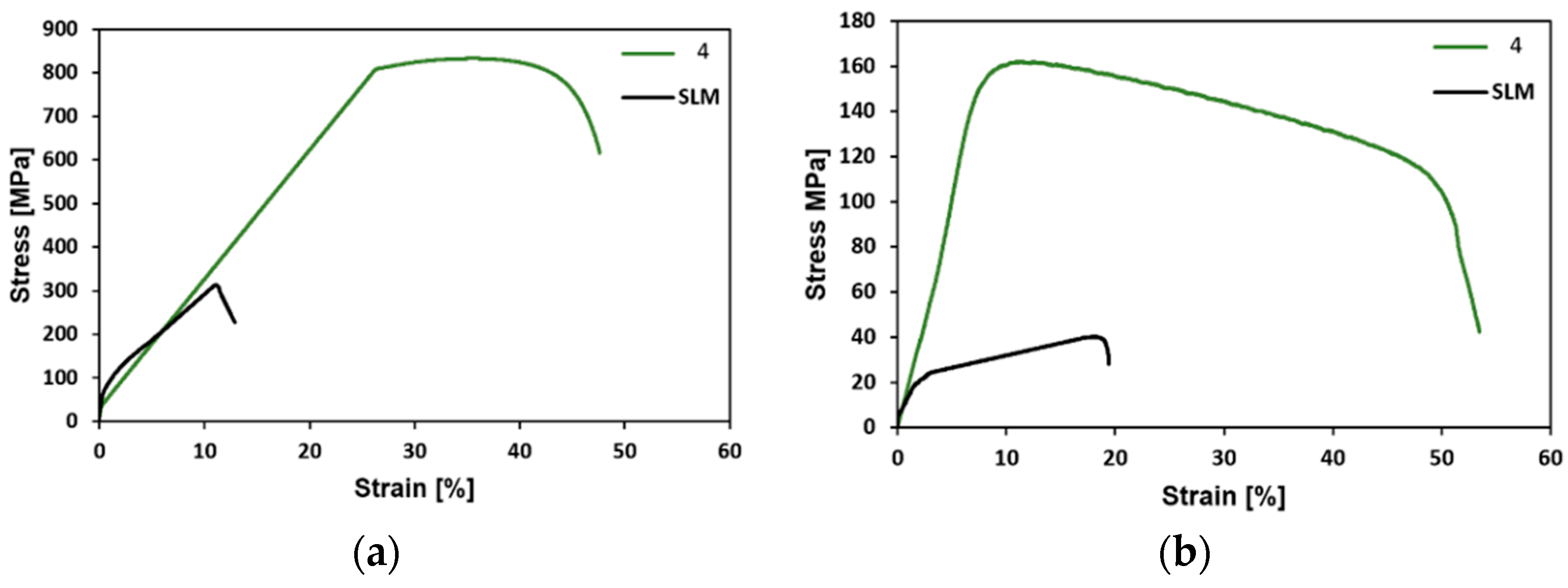
Last but not least, the final swaged rods were subjected to tensile testing at room temperature and at 900 °C. For comparison, the original SLM material was examined as well. The stress-strain curves acquired at room temperature are depicted in Figure 7a, whereas the results of tensile testing at 900 °C are shown in Figure 7b. With regards to the plasticity, the swaging evidently introduced a significant increase in this parameter. The elongation for failure was lower than 20% for the SLM sample even when tested at 900 °C, whereas the ductility of the final swaged rod was already at almost 50% at room temperature, and exceeded 50% when tested at 900 °C. The swaged rod also exhibited a substantial increase in strength; the room temperature ultimate tensile strength (UTS) of the SLM sample was 314 MPa, whereas the final swaged piece (sample 4) exhibited the room temperature UTS of more than 800 MPa. At the elevated temperature of 900 °C, the UTS of sample 4 still reached up to more than 160 MPa, while the UTS of the SLM sample was as low as 40 MPa.
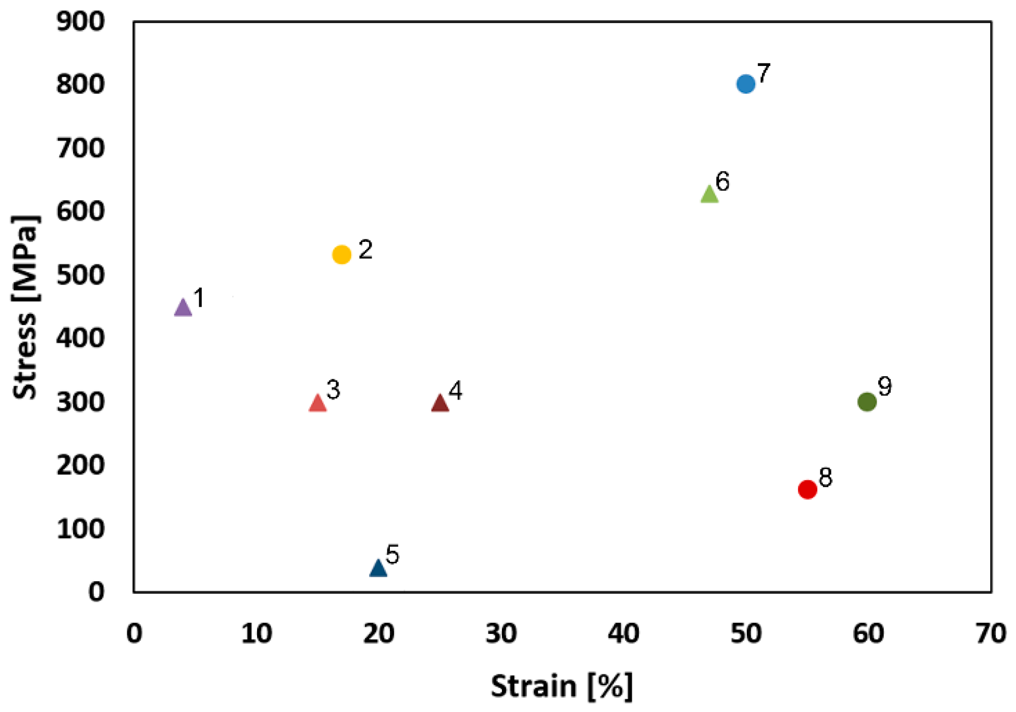
Compared with the SLM sample, sample 4 exhibited a substantial increase in strength (UTS), as well as in plasticity. The rapidly increasing mechanical properties, particularly strength, can be attributed to several factors. One of them is the observed substructural formation and corresponding increase in the dislocation density. Another factor which must be stressed upon is the development of other structural phenomena (e.g., deformation bands) that are very effective for strengthening. On the other hand, the favorable ductility of the swaged piece was imparted primarily by the extreme reduction of the porosity when compared with the SLM sample (Figure 5a,b). Furthermore, the 3D-printed materials feature a non-homogenous stress state even when a post-process heat treatment is applied. Usually, the tensile residual stress prevails in the (sub)surface regions of a 3D-printed part, whereas the compressive stress is localized in the remaining material volume. The presence of the residual stress, together with the observed porosity, were most probably the reasons for the relatively low UTS value acquired for the SLM sample—when compared to others (e.g., Pruncu et al. [25] acquired the UTS of ~450 MPa for a SLM-manufactured AISI 316L workpiece built with its axis parallel to the building substrate). It is generally known that the plasticity decreases dramatically with the increasing porosity. The hot rotary swaging, particularly given by the applied intensive shear strain, was evidently able to reduce the level of porosity, as well as favorably affect the original stress state of the 3D-printed workpiece, which resulted in the final enhancement of the overall performance of the swaged AISI 316L steel rod. The comparison with other plastic deformation methods, which can be used to post process 3D-printed AISI 316L workpieces, shows that the hot rotary swaging imparts a mechanical behavior superior to that acquired e.g., after hot forging, the acquired UTS was ~ 530 MPa and the elongation to failure was approx. 17% [25]. The depiction of the comparison of the UTS values acquired within the presented study with the results presented by others can be seen in Figure 8.
4. Conclusions
The study investigated the effects of hot rotary swaging on structural and mechanical properties of an AISI 316L stainless steel workpiece manufactured by selective laser melting. The swaging led to an almost complete elimination of the porosity (decrease by ~98%), which went hand in hand with the structural refinement and development of the substructure. The acquired structural modifications resulted in an increase in the microhardness up to almost 300 HV1, as well as enhanced tensile properties at both room temperature and 900 °C. The room temperature ultimate tensile strength (UTS) increased almost three times after the swaging and exceeded 800 MPa. At 900 °C, the UTS of the swaged piece was more than four times higher when compared with the as-printed workpiece. Suffice to say, the implementation of the hot rotary swaging substantially enhanced the overall performance of the as-printed AISI 316L workpiece.
Author Contributions
Conceptualization, M.B. and R.K.; Investigation, L.K., M.B. and J.D.; Methodology, R.K. and J.D. Visualization, R.K.; Writing—original draft, L.K. and M.B. All authors have read and agreed to the published version of the manuscript.
Funding
The authors acknowledge the support of project no. 22-11949S by the Czech Science Foundation.
Institutional Review Board Statement
Not applicable.
Informed Consent Statement
Not applicable.
Data Availability Statement
The original data supporting the research is not publicly available but the data that is not confidential is available upon request from the corresponding author.
Acknowledgments
We acknowledge the help of the LaPaMat team of the Institute of Physics of Materials, CAS.
Conflicts of Interest
The authors declare no conflict of interest. The funders had no role in the design of the study, in the collection, analyses, or interpretation of data, in the writing of the manuscript, or in the decision to publish the results.
References
- Zhu, Z.; Li, W.; Nguyen, Q.B.; An, X.; Lu, W.; Li, Z.; Ng, F.L.; Nai, S.M.L.; Wei, J. Enhanced strength–ductility synergy and transformation-induced plasticity of the selective laser melting fabricated 304L stainless steel. Addit. Manuf. 2020, 35, 101300. [Google Scholar] [CrossRef]
- Ghayoor, M.; Lee, K.; He, Y.; Chang, C.-H.; Paul, B.K.; Pasebani, S. Selective laser melting of 304L stainless steel: Role of volumetric energy density on the microstructure, texture and mechanical properties. Addit. Manuf. 2020, 35, 101011. [Google Scholar] [CrossRef]
- Saxena, P.; Gajera, H.; Shah, D.; Pancholi, N. Effect of SLM process parameters on hardness and microstructure of stainless steel 316 material. Mater. Today Proc. 2022, 50, 1653–1659. [Google Scholar] [CrossRef]
- Lanzutti, A.; Marin, E.; Tamura, K.; Morita, T.; Mangan, M.; Vaglio, E.; Andreatta, F.; Sortino, M.; Totis, G.; Fedrizzi, L. High temperature study of the evolution of the tribolayer in additively manufactured AISI 316L steel. Addit. Manuf. 2020, 34, 101258. [Google Scholar] [CrossRef]
- Takata, N.; Liu, M.; Kodaira, H.; Suzuki, A.; Kobashi, M. Anomalous strengthening by supersaturated solid solutions of selectively laser melted Al–Si-based alloys. Addit. Manuf. 2020, 33, 101152. [Google Scholar] [CrossRef]
- Liu, Y.; Meng, J.; Zhu, L.; Chen, H.; Li, Z.; Li, S.; Wang, D.; Wang, Y.; Kosiba, K. Dynamic compressive properties and underlying failure mechanisms of selective laser melted Ti-6Al-4V alloy under high temperature and strain rate conditions. Addit. Manuf. 2022, 54, 102772. [Google Scholar] [CrossRef]
- Liu, S.; Geethapriyan, T.; Muthuramalingam, T.; Shanmugam, R.; Ramoni, M. Influence of heat-treated Cu–Be electrode on machining accuracy in ECMM with Monel 400 alloy. Arch. Civ. Mech. Eng. 2022, 22, 154. [Google Scholar] [CrossRef]
- Shanmugam, R.; Ramoni, M.; Thangamani, G.; Thangaraj, M. Influence of Additive Manufactured Stainless Steel Tool Electrode on Machinability of Beta Titanium Alloy. Met. Basel 2021, 11, 778. [Google Scholar] [CrossRef]
- Han, Y.; Zhang, Y.; Jing, H.; Lin, D.; Zhao, L.; Xu, L.; Xin, P. Selective laser melting of low-content graphene nanoplatelets reinforced 316L austenitic stainless-steel matrix: Strength enhancement without affecting ductility. Addit. Manuf. 2020, 34, 101381. [Google Scholar] [CrossRef]
- Kim, S.H.; Lee, H.; Yeon, S.M.; Aranas Jr, C.; Choi, K.; Yoon, J.; Yang, S.W.; Lee, H. Selective compositional range exclusion via directed energy deposition to produce a defect-free Inconel 718/SS 316L functionally graded material. Addit. Manuf. 2021, 47, 102288. [Google Scholar] [CrossRef]
- Dryepondt, S.; Nandwana, P.; Zelaia, P.F.; List, F. Microstructure and high temperature tensile properties of 316L fabricated by laser powder-bed fusion. Addit. Manuf. 2021, 37, 101723. [Google Scholar] [CrossRef]
- Waqar, S.; Guo, K.; Sun, J. Evolution of residual stress behavior in selective laser melting (SLM) of 316L stainless steel through preheating and in-situ re-scanning techniques. Opt. Laser Technol. 2022, 149, 107806. [Google Scholar] [CrossRef]
- Tang, M.; Pistorius, P.C. Anisotropic Mechanical Behavior of AlSi10Mg Parts Produced by Selective Laser Melting. JOM 2017, 69, 516–522. [Google Scholar] [CrossRef]
- Sercombe, T.; Jones, N.; Day, R.; Kop, A. Heat treatment of Ti-6Al-7Nb components produced by selective laser melting. Rapid Prototyp. J. 2008, 14, 300–304. [Google Scholar] [CrossRef]
- Aboulkhair, N.T.; Everitt, N.M.; Ashcroft, I.; Tuck, C. Reducing porosity in AlSi10Mg parts processed by selective laser melting. Addit. Manuf. 2014, 1–4, 77–86. [Google Scholar] [CrossRef]
- Moeini, G.; Sajadifar, S.V.; Wegener, T.; Brenne, F.; Niendorf, T.; Böhm, S. On the low-cycle fatigue behavior of friction stir welded Al–Si12 parts produced by selective laser melting. Mater. Sci. Eng. A 2019, 764, 138189. [Google Scholar] [CrossRef]
- Jamili, A.M.; Zarei-Hanzaki, A.; Abedi, H.R.; Mosayebi, M.; Kocich, R.; Kunčická, L. Development of fresh and fully recrystallized microstructures through friction stir processing of a rare earth bearing magnesium alloy. Mater. Sci. Eng. 2020, 775, 138837. [Google Scholar] [CrossRef]
- Kocich, R.; Kunčická, L.; Král, P.; Lowe, T.C. Texture, deformation twinning and hardening in a newly developed Mg–Dy–Al–Zn–Zr alloy processed with high pressure torsion. Mater. Des. 2016, 90, 1092–1099. [Google Scholar] [CrossRef]
- Yusuf, S.M.; Hoegden, M.; Gao, N. Effect of sample orientation on the microstructure and microhardness of additively manufactured AlSi10Mg processed by high-pressure torsion. Int. J. Adv. Manuf. Technol. 2020, 106, 4321–4337. [Google Scholar] [CrossRef]
- Kunčická, L.; Kocich, R.; Drápala, J.; Andreyachenko, V.A. FEM simulations comparison of the ECAP and ECAP-PBP influence on Ti6Al4V alloy’s deformation behavior. In METAL 2013, Proceedings of the 22nd International Conference on Metallurgy and Materials, Brno, Czech Republic, 15–17 May 2013; TANGER Ltd.: Greensboro, NC, USA, 2013; pp. 391–396. [Google Scholar]
- Sun, C.; Liu, H.; Wan, C.; Ju, J.; Wan, G.; Jia, J.; Ma, A.; Bai, J.; Xue, F.; Xin, Y. Anisotropy investigation of an ECAP-processed Mg-Al-Ca-Mn alloy with synergistically enhanced mechanical properties and corrosion resistance. J. Alloys Compd. 2022, 911, 165046. [Google Scholar] [CrossRef]
- Kocich, R.; Kunčická, L. Development of structure and properties in bimetallic Al/Cu sandwich composite during cumulative severe plastic deformation. J. Sandw. Struct. Mater. 2021, 23, 4252–4275. [Google Scholar] [CrossRef]
- Kunčická, L.; Kocich, R.; Ryukhtin, V.; Culllen, J.C.T.; Lavery, N.P. Study of structure of naturally aged aluminium after twist channel angular pressing. Mater. Charact. 2019, 152, 94–100. [Google Scholar] [CrossRef]
- Hosseinzadeh, A.; Radi, A.; Richter, J.; Wegener, T.; Sajadifar, S.V.; Niendorf, T.; Yapici, G.G. Severe plastic deformation as a processing tool for strengthening of additive manufactured alloys. J. Manuf. Process. 2021, 68, 788–795. [Google Scholar] [CrossRef]
- Pruncu, C.I.; Hopper, C.; Hooper, P.A.; Tan, Z.; Zhu, H.; Lin, J.; Jiang, J. Study of the Effects of Hot Forging on the Additively Manufactured Stainless Steel Preforms. J. Manuf. Process. 2020, 57, 668–676. [Google Scholar] [CrossRef]
- Bambach, M.; Sizova, I.; Emdadi, A. Development of a processing route for Ti-6Al-4V forgings based on preforms made by selective laser melting. J. Manuf. Process. 2019, 37, 150–158. [Google Scholar] [CrossRef]
- Bambach, M.; Sizova, I.; Szyndler, J.; Bennnett, J.; Hyatt, G.; Cao, J.; Papke, T.; Merklein, M. On the hot deformation behavior of Ti-6Al-4V made by additive manufacturing. J. Mater. Process. Technol. 2021, 288, 116840. [Google Scholar] [CrossRef]
- Gamin, Y.V.; Bolaños, J.A.M.; Aleschenko, A.S.; Komissarov, A.A.; Bunits, N.S.; Nikolaev, D.A.; Fomin, A.V.; Cheverikin, V.V. Influence of the radial-shear rolling (RSR) process on the microstructure, electrical conductivity and mechanical properties of a Cu–Ni–Cr–Si alloy. Mater. Sci. Eng. A 2021, 822, 141676. [Google Scholar] [CrossRef]
- Wang, Z.; Chen, J.; Besnard, C.; Kunčická, L.; Kocich, R.; Korsunsky, A.M. In situ neutron diffraction investigation of texture-dependent Shape Memory Effect in a near equiatomic NiTi alloy. Acta Mater. 2021, 202, 135–148. [Google Scholar] [CrossRef]
- Kunčická, L.; Kocich, R. Deformation behaviour of Cu-Al clad composites produced by rotary swaging. Mater. Sci. Eng. 2018, 369, 012029. [Google Scholar] [CrossRef]
- Sheremetyev, V.; Kudryashova, A.; Cheverikin, V.; Korotitskiy, A.; Galkin, S.; Prokoshkin, S.; Brailovski, V. Hot radial shear rolling and rotary forging of metastable beta Ti-18Zr-14Nb (at. %) alloy for bone implants: Microstructure, texture and functional properties. J. Alloys Compd. 2019, 800, 320–326. [Google Scholar] [CrossRef]
- Kunčická, L.; Macháčková, A.; Lavery, N.P.; Kocich, R.; Cullen, J.T.; Hlaváč, L.M. Effect of thermomechanical processing via rotary swaging on properties and residual stress within tungsten heavy alloy. Int. J. Refract. Met. Hard Mater. 2020, 87, 105120. [Google Scholar] [CrossRef]
- García, C.; Martín, F.; Tiedra, P.; Cambronero, L.G. Pitting corrosion behaviour of PM austenitic stainless steels sintered in nitrogen–hydrogen atmosphere. Corros. Sci. 2007, 49, 1718–1736. [Google Scholar] [CrossRef]
- Saeidi, K.; Gao, X.; Zhong, Y.; Shen, Z.J. Hardened austenite steel with columnar sub-grain structure formed by laser melting. Mater. Sci. Eng. 2015, 625, 221–229. [Google Scholar] [CrossRef]
- Sefene, E.M. State-of-the-art of selective laser melting process: A comprehensive review. J. Manuf. Syst. 2022, 63, 250–274. [Google Scholar] [CrossRef]
- Verlinden, B.; Driver, J.; Samajdar, I.; Doherty, R.D. Thermo-Mechanical Processing of Metallic Materials; Elsevier: Amsterdam, The Netherlands, 2007; p. 560. [Google Scholar]
- Humphreys, F.J.; Hetherly, M. Recrystallization and Related Annealing Phenomena, 2nd ed.; Elsevier Ltd.: Oxford, UK, 2004; p. 628. [Google Scholar]
- Russel, A.; Lee, K.L. Structure-Property Relations in Nonferrous Metals, 1st ed.; John Wiley & Sons Inc.: Hoboken, NJ, USA, 2005; p. 520. [Google Scholar]
- Montero-Sistiaga, M.L.; Godino-Martinez, M.; Boschmans, K.; Kruth, J.-P.; Van Humbeeck, J.; Vanmeensel, K. Microstructure evolution of 316L produced by HP-SLM (high power selective laser melting). Addit. Manuf. 2018, 23, 402–410. [Google Scholar] [CrossRef]
- Byun, T.S.; Garrison, B.E.; McAlister, M.R.; Chen, X.; Gussev, M.N.; Lach, T.G.; Le Coq, A.; Linton, K.; Joslin, C.B.; Carver, J.K.; et al. Mechanical behavior of additively manufactured and wrought 316L stainless steels before and after neutron irradiation. J. Nucl. Mater. 2021, 548, 152849. [Google Scholar] [CrossRef]
Figure 1.
Schematic depiction of the experimental swaging process.

Figure 2.
EBSD band contrast images with HAGBs depicted in black, and LAGBs depicted in green: SLM sample (a); sample 1 (b); sample 2 (c); sample 3 (d); sample 4 (e).
Figure 2.
EBSD band contrast images with HAGBs depicted in black, and LAGBs depicted in green: SLM sample (a); sample 1 (b); sample 2 (c); sample 3 (d); sample 4 (e).

Figure 3.
Average grain areas for the examined samples (a). Grain area distributions for: sample 1 peripheral region (b); sample 1 axial region (c); sample 4 peripheral region (d); sample 4 axial region (e).
Figure 3.
Average grain areas for the examined samples (a). Grain area distributions for: sample 1 peripheral region (b); sample 1 axial region (c); sample 4 peripheral region (d); sample 4 axial region (e).

Figure 4.
IPF texture images for: SLM sample (a); 1 sample (b); 2 sample (c); 3 sample (d); 4 sample (e).
Figure 4.
IPF texture images for: SLM sample (a); 1 sample (b); 2 sample (c); 3 sample (d); 4 sample (e).


Figure 5.
Results of the analyses of the porosity: SLM sample (a); 4 sample (b).

Figure 6.
Distributions of the HV1 microhardness values across the cross-sections of the examined samples.
Figure 6.
Distributions of the HV1 microhardness values across the cross-sections of the examined samples.

Figure 7.
Tensile test stress-strain curves for the SLM workpiece and the 4 swaged piece acquired at: room temperature (a); 900 °C (b).
Figure 7.
Tensile test stress-strain curves for the SLM workpiece and the 4 swaged piece acquired at: room temperature (a); 900 °C (b).

Figure 8.
Comparison of the aquired results of the mechanical properties (UTS values) with UTS values of the 3D-printed and deformation-processed AISI 316L steel presented in the available literature. Legend to the individual points: 1—high laser power sample by Montero-Sistiaga et al. [39]; 2—Pruncu et al. [25]; 3—SLM sample at room temperature; 4—Dryepondt et al. [11]; 5—SLM sample at 900 °C; 6—low laser power sample by Montero-Sistiaga et al. [39]; 7—sample 4 at room temperature; 8—sample 4 at 900 °C; 9—Byun et al. [40].

Publisher’s Note: MDPI stays neutral with regard to jurisdictional claims in published maps and institutional affiliations. |
© 2022 by the authors. Licensee MDPI, Basel, Switzerland. This article is an open access article distributed under the terms and conditions of the Creative Commons Attribution (CC BY) license (https://creativecommons.org/licenses/by/4.0/).
Share and Cite
MDPI and ACS Style
Kunčická, L.; Kocich, R.; Benč, M.; Dvořák, J. Affecting Microstructure and Properties of Additively Manufactured AISI 316L Steel by Rotary Swaging. Materials 2022, 15, 6291. https://doi.org/10.3390/ma15186291
AMA Style
Kunčická L, Kocich R, Benč M, Dvořák J. Affecting Microstructure and Properties of Additively Manufactured AISI 316L Steel by Rotary Swaging. Materials. 2022; 15(18):6291. https://doi.org/10.3390/ma15186291
Chicago/Turabian StyleKunčická, Lenka, Radim Kocich, Marek Benč, and Jiří Dvořák. 2022. "Affecting Microstructure and Properties of Additively Manufactured AISI 316L Steel by Rotary Swaging" Materials 15, no. 18: 6291. https://doi.org/10.3390/ma15186291
Note that from the first issue of 2016, this journal uses article numbers instead of page numbers. See further details here.