
High Heat Flux Testing of Graded W-Steel Joining Concepts for the First Wall
by
 , , , and
Vishnu Ganesh
1,*,
Daniel Dorow-Gerspach
1,*,
Martin Bram
1,2,
Christian Linsmeier
1 ,
,
Jiri Matejicek
3 and
Monika Vilemova
3 1
Forschungszentrum Jülich GmbH, Institut für Energie- und Klimaforschung, 52425 Jülich, Germany
2
Institut für Werkstoffe, Ruhr-Universität Bochum, 44781 Bochum, Germany
3
Institute of Plasma Physics of the Czech Academy of Sciences, 182 00 Prague, Czech Republic
*
Authors to whom correspondence should be addressed.
Energies 2023, 16(9), 3664; https://doi.org/10.3390/en16093664
Submission received: 17 March 2023
/
Revised: 19 April 2023
/
Accepted: 23 April 2023
/
Published: 24 April 2023
(This article belongs to the Special Issue Water Coolant Lithium Lead Breeding Blanket and Test Blanket Module: Design and R&D Activities in 2022)
Abstract
:The realization of the first wall (FW), which is composed of a protective tungsten (W) armor covering the structural steel material, is a critical challenge in the development of future fusion reactors. Due to the different coefficients of thermal expansion (CTE) of W and steel, the direct joining of them results in cyclic thermal stress at their bonding seam during the operation of the fusion reactor. To address this issue, this study benchmarks two joining concepts. The first concept uses an atmospheric plasma sprayed graded interlayer composed of W/steel composites with a varying content of W and steel to gradually change the CTE. The second concept uses a spark plasma sintered graded interlayer. Furthermore, in order to benchmark these concepts, a directly bonded W-steel reference joint as well as a W-steel joint featuring a vanadium interlayer were also tested. These joints were tested under steady-state high heat flux cyclic loading, starting from a heat flux of 1 MW/m2 up to 4.5 MW/m2, with stepwise increments of 0.5 MW/m2. At each heat flux level, 200 thermal cycles were performed. The joints featuring a sintered graded interlayer survived only until 1.5 MW/m2 of loading, while the joint featuring plasma sprayed graded interlayer and V interlayer survived until 3 MW/m2.
1. Introduction
The blanket first wall (FW), which is a plasma-facing component (PFC) in future fusion reactors, will likely feature a tungsten (W) armor as the plasma-facing material [1]. This is due to its suitable resistance against erosion caused by particle loading. A W armor in the FW is also envisaged during the pre-conceptual design phase of the EU DEMO breeding blankets [2,3]. This armor will protect the underlying structural material from plasma sputtering and erosion [3]. Currently, Eurofer 97 steel—a European reduced activation ferritic/martensitic steel—is expected to be the structural material. This raises the question of how to join W and steel. It was mentioned by Catanzaro et al. [2] that the presence of W armor attached to steel exerts thermal stresses onto the FW due to their different coefficients of thermal expansion (CTE). It is believed that this thermally induced stress might cause premature thermal fatigue failure of the FW during operation of the fusion reactor. To mitigate this issue, an interlayer with an appropriate CTE can be inserted between the W and steel to alleviate the CTE mismatch and redistribute the macroscopic thermal stresses.
One of the concepts under investigation is the use of a functionally graded material (FGM) as an interlayer between W and steel. The FGM is a W/steel composite with a gradually varying concentration of W and steel, resulting in a gradual variation in its CTE. The resulting joint is known as a graded joint. According to a rudimentary finite element (FE) numerical simulation by Heuer et al. [4], the use of FGM has been shown to redistribute macroscopic thermal stress and reduce plastic deformation in the steel of the FW [4]. The FGM is composed of multiple layers of W/steel composites with varying vol% of W present over one another. Heuer et al. [4] proposed using a three-layer FGM as an appropriate compromise to limit the complexity of manufacturing as well as to minimize the plastic deformation in steel. The three layers are composites of the following vol% of W: 25, 50, and 75%, with the remainder being steel. For ease of reading, these composites will be referred to as 25W, 50W, and 75W, respectively. Another rudimentary FE numerical study by Qu et al. [5], suggested that a thicker FGM can drastically reduce creep strains in steel and improve its lifetime. Both of these studies propose exploiting plasma spraying and powder metallurgical routes to produce thick FGMs. In the case of plasma spraying, a modified atmospheric plasma spraying (APS) has been intensively investigated due to several advantages of the spraying process, such as the capability to coat larger areas, relatively low cost, and the ability to produce thicker coatings [6,7,8]. Although there have been many investigations conducted on the development of composites using APS, to date, no work has reported the manufacturing of a complete graded joint. Therefore, within the framework of this study, we have manufactured an optimized graded joint consisting of a three-layer atmospheric plasma sprayed FGM by optimizing the processing parameters [7]. In the case of powder metallurgy, a field-assisted sintering technology/spark plasma sintering (FAST/SPS) is an attractive technique, particularly due to its ability to reduce the sintering temperature and time compared to conventional powder metallurgy processes. Therefore, we utilized the FAST/SPS process and optimized the sintering parameters to produce dense composites, as mentioned in our previous work [9].
These two concepts have not yet been tested under cyclic high heat flux (HHF) loading to experimentally demonstrate their thermal fatigue response. An HHF test is a vital technique to qualify/corroborate PFCs by simulating reactor-relevant heat loads to predict their lifetime experimentally. Thus, considering this research gap, this paper aims to cover the following objectives: first, to perform a steady-state HHF cyclic benchmarking test on these two graded joining concepts, which were already manufactured in our earlier works by subjecting them to multiple heat loads. Second, it is also vital to compare them with a reference joint to see how well these concepts improve the lifetime. Therefore, a directly bonded reference W-steel joint was also tested under same loading conditions. Third, in a study conducted by Hirose et al. [10], W and steel were successfully bonded directly. It was reported that the direct bonding has promising prospects, and further studies are needed to fully understand its potential. However, no work has reported HHF testing of the directly bonded joint. Thus, this paper also aims to cover this research gap. Overall, this paper aims to contribute to the understanding of the graded joining concepts and provide key learnings for necessary future works.
2. Components and Testing Methodology
2.1. Overview of the Manufactured W and Steel Joints
The base materials were ITER-grade W produced by Plansee SE and Eurofer 97 steel plate provided by Karlsruhe Institute of Technology. These materials were cut into the necessary geometries using wire electric discharge machining. Each manufactured joint consisted of 3 mm thick ITER-grade W at the top and Eurofer 97 steel of same thickness at the bottom; this makes it possible to benchmark different concepts in a simple and straightforward manner. For ease of reference, the ITER-grade W and Eurofer 97 steel are referred as W-tile and steel, respectively.
The first joining concept developed was a graded joint consisting of atmospheric plasma sprayed FGM. The layers of this FGM were prepared by plasma spraying in an argon-shrouded chamber using a water/argon stabilized plasma torch WSP-H. The full joint was then manufactured using a current-assisted diffusion bonding (CA-DB) process with the help of lab scale FAST/SPS equipment [7]. As can be seen in the scanning electron microscopy (SEM) micrograph of the joint in Table 1, the W-tile was bonded to the FGM with the help of a thin V-filler (~0.3 mm), as it was not possible to bond the W-tile and the FGM directly. As mentioned in our previous study, the V-filler was necessary to manufacture this graded joint and test this concept under HHF loading [7]. The intended thickness of the individual FGM layers was approximately 0.5 mm, although the thickness reduced slightly after joining. The second joining concept developed was a similar graded joint consisting of spark plasma sintered FGM. These sintered composites were the outcome of our previous study, where the processing parameters were optimized to produce very dense composites [9]. The graded joint was manufactured using the same lab scale FAST/SPS equipment. Unlike the FGM-APS joint, the W-tile and FGM were directly bonded without requiring any filler material, as shown in Table 1.
As the FGM-APS joint has a thin V-filler to bond the FGM and the W-tile, it is vital to compare it to a joint consisting of only a V interlayer. Thus, a joint featuring a 1.5 mm-thick V interlayer was also manufactured using the same CA-DB process. The thickness was kept the same as that of FGM-APS joint, as shown in Table 1 for a straightforward comparison. Additionally, the joining temperature and time were same as those used for the FGM-APS joint. The fourth joint served as a reference joint, which is a directly bonded W and steel manufactured using the same CA-DB process. Although the joining temperature was consistent with the others, the joining time was limited to 15 min to minimize the amount of formation of brittle intermetallic phases (FexWy) at the W-steel bond seam. The cross-sectional micrograph can be seen in Table 1.
2.2. HHF Testing Procedure
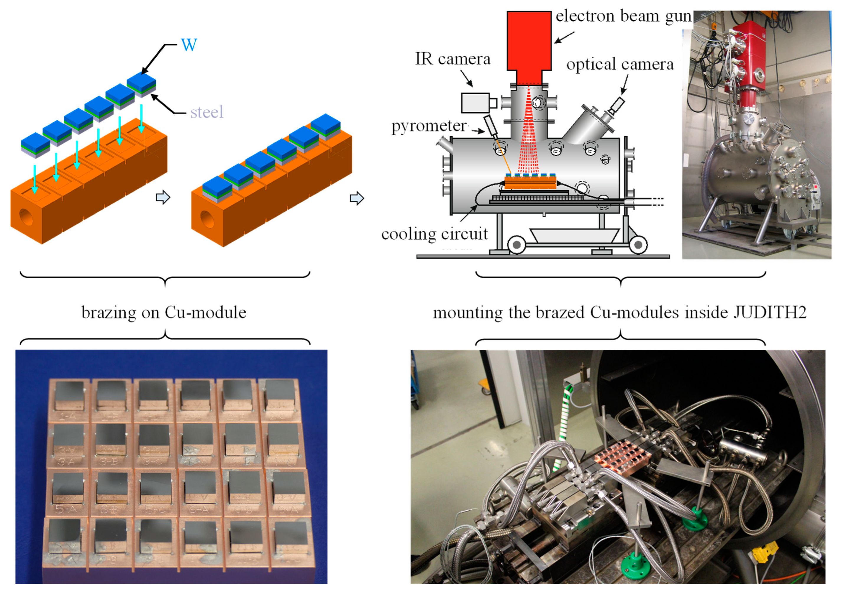
The manufactured small-scale joints were standardized to a geometry of 12 mm × 12 mm. The top side of the W-tile was polished to a mirror finish to ensure surface consistency for each joint. The bottom side of the steel was slightly ground to remove any grease/contamination and then brazed onto an actively cooled copper module (heat sink) with dimensions of 26 mm × 26 mm × 104 mm. The copper module included a cooling channel in the middle with a diameter of 11 mm, as illustrated schematically in Figure 1. This technique of brazing the joints on an actively cooled copper module was utilized in several studies in order to perform the HHF testing on small-scale components [11,12,13]. A 100 μm thick silver-based industrial brazing foil with a melting temperature of approximately 800 °C was used for the brazing process. This brazing temperature was selected based on previous studies that also used this silver-based brazing foil to attach joints on to the actively cooled copper module [11,12,13].
The brazed modules were then mounted inside the electron beam facility known as JUDITH 2 located at Forschungszentrum Jülich GmbH. The cooling conditions were chosen to be easily accessible and adequate to ensure that they are not the limiting factor. Therefore, the coolant temperature was set to 20 °C, which is the normal operating temperature of the water-cooling system. The coolant pressure and flow rate were kept high enough to achieve maximum cooling performance. The values were set to 25 bar and 80 L/min, respectively, considering the technical specifications of the water-cooling system [14]. The combined flow rate of 80 L/min was distributed to four Cu modules, as can be seen in Figure 1. Thus, the coolant conditions during the test were as follows: water flowing at 20 °C, 3.5 m/s, 25 bar.
It must be noted that the coolant conditions during this test were not the same as the normal operating conditions of the coolant in an actual FW of a future fusion reactor. For instance, in the case of a proposed water-cooled lead–lithium (WCLL) breeding blanket, the water would flow through the steel heat sink at 155 bar and 295–328 °C [3]. Thus, the results of this test must not be confused/compared with those obtained under actual FW conditions. In fact, the aim of this study was to compare the lifetime/performance of different joining concepts within each other, not to determine the lifetime of an actual FW.
2.3. Thermal Loading Protocol
The installed joints were tested under steady-state cyclic loading at various heat fluxes which are listed in Table 2. Initially, the joints were loaded with a constant heat flux of 1 MW/m2 until steady-state was achieved, also known as the screening test at 1 MW/m2. Screening refers to the scenario in which the temperature gradient controlled by the applied loading and the coolant reaches steady-state. It was observed that steady-state was achieved within 20 s during the initial screening, and the observed surface temperatures were homogenous, revealing no local defects. Subsequently, cyclic testing was initiated with an ON/OFF loading time of 30/30 s. This duration represents the time during which the electron beam was turned ON and OFF. The surface temperature of the W-tile reached steady-state within this ON time and is referred to as Tsurf. For the next 30 s (OFF time), the entire joint cooled down to the coolant temperature (20 °C). This ON and OFF time constituted one thermal cycle. The cyclic testing was performed starting from a heat flux of 1 MW/m2 and increased in steps of 0.5 MW/m2 up to 4.5 MW/m2, until all the joints failed. At each heat flux, a screening test was performed first, followed by 200 thermal cycles. To limit the cost/time of the experimental campaign, the number of thermal loading cycles was restricted to 200 cycles for each heat flux (see Table 2). It must be noted that during the normal operation in a future fusion reactor, the heat fluxes arising from the particle loading and photonic radiation from the hot plasma at the FW would be significantly lower than 1 MW/m2 [15]. However, the rationale behind choosing higher heat loads in our study was to test all joints up to their limit with a minimum time/cost investment of the experimental campaign. The surface temperatures of the W-tiles were measured/monitored using an infrared sensor.
2.4. Post Mortem Analysis
After the joints failed, a microscopic study of the failure location was conducted with the help of SEM microscopy. For the sake of brevity and to respect the length of this paper, only a concise summary of the failure pattern is provided. The corresponding micrographs are provided in the supplementary materials.
3. Results
3.1. Temperature Evolution of Joints
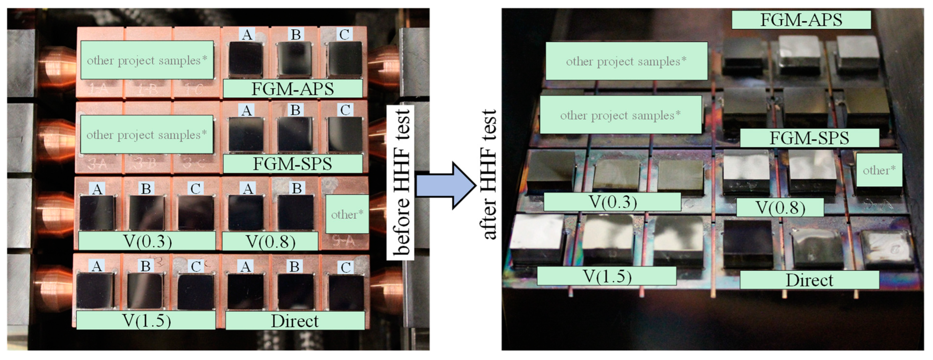
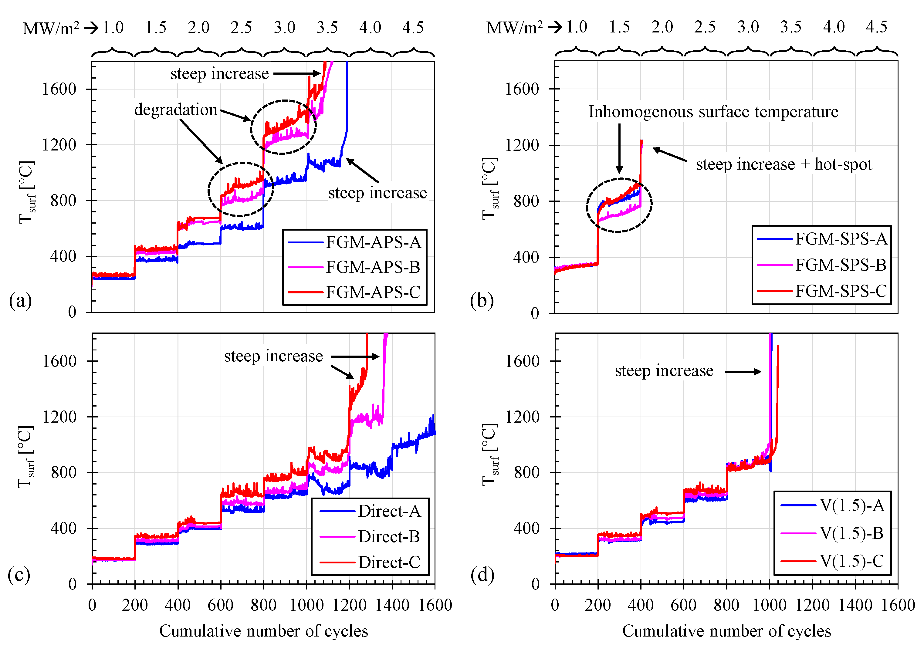
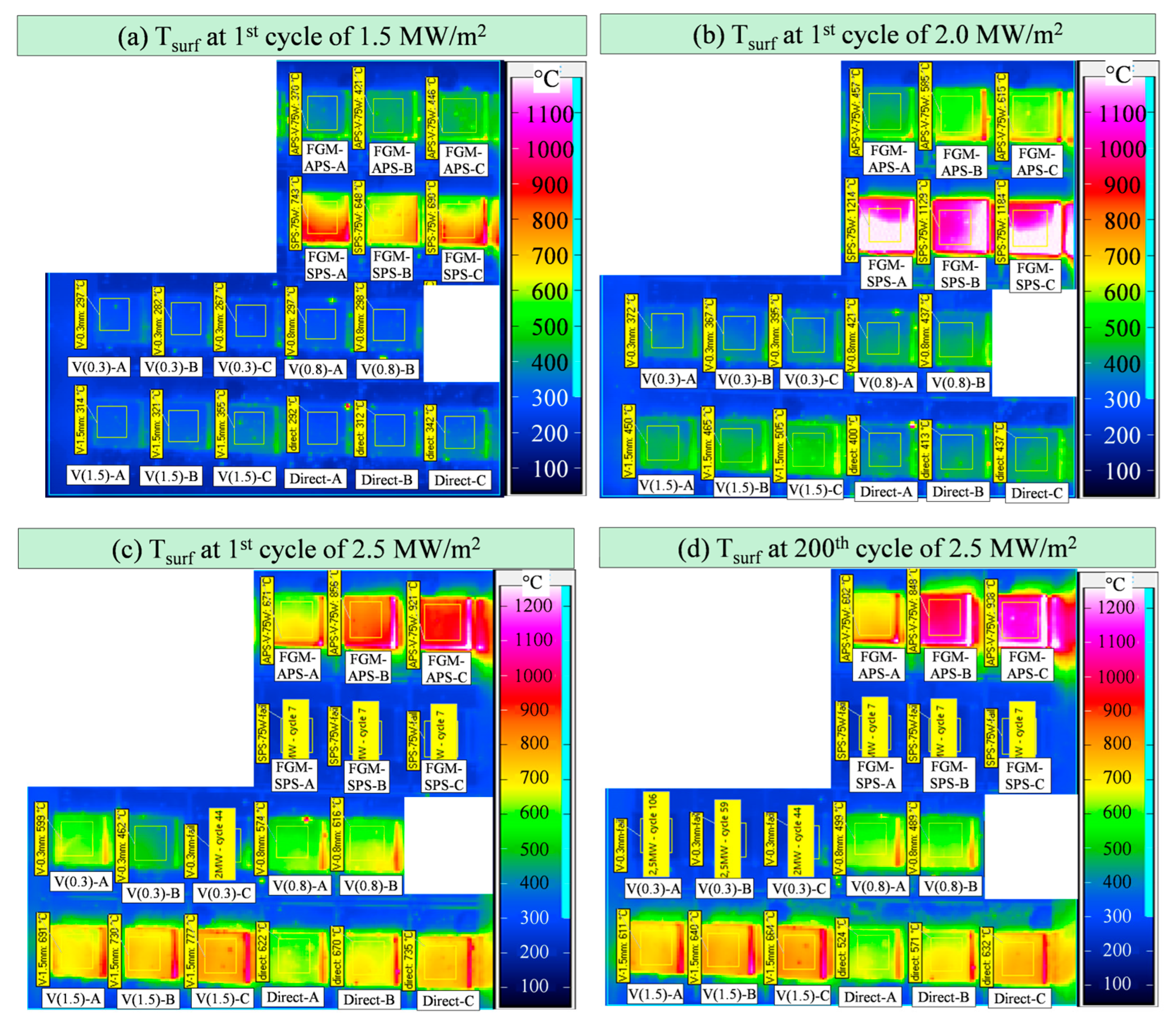
The macroscopic photograph of the joints before and after HHF testing is shown in Figure 2. The monitored Tsurf over the entire HHF testing is depicted in Figure 3. As shown in the figure, the temperature increased in a stepwise fashion with stepwise increase in the heat flux. The monitored Tsurf remained relatively constant at each heat flux, except for the graded joints which exhibited some degree of degradation (increasing Tsurf) with each thermal cycle at higher heat fluxes. For instance, as shown in Figure 3a, two samples (B and C) of the graded joint consisting of a plasma sprayed FGM interlayer exhibited degradation starting at 2.5 MW/m2. It was observed that the temperature increased by approximately 100 °C over 200 cycles at 2.5 MW/m2 and by 200 °C at 3 MW/m2. However, the temperature of the W-tile was homogenous without any hot spots, as depicted in Figure 4c,d. This finding suggests that the temperature increase was not due to cracks at the bonding seam, but due to uniform and continuous deterioration of the joint, such as a reduction of the thermal conductivity of interlayer. At 3.5 MW/m2, all three FGM-APS joints showed a steep and sudden increase in temperature. This indicated that the bonding seams had eventually led to debonding/cracks, causing a catastrophic failure of the joint.
In contrast, the graded joint consisting of sintered FGM exhibited a relatively stable Tsurf until cycling at 1 MW/m2, but started to became inhomogeneous during the 1.5 MW/m2 loading phase, as can be seen in Figure 4a, which persisted further. This indicates cracks at the bonding seam, indicating that the W-tile had partially detached. Furthermore, this joint also exhibited an extremely high surface temperature compared to the other joints just at the beginning of the 2 MW/m2 loading, as can be seen in Figure 3b and Figure 4b, and ultimately failed completely. The joint featuring a V interlayer and a directly bonded reference joint did not show any signs of deterioration, but failed catastrophically at the beginning of the 3.5 MW/m2 loading and between the 4 MW/m2 and 4.5 MW/m2 loading, respectively, as can be seen in Figure 3c,d. Sample A of the direct joint showed an inhomogeneous surface temperature at the end of the 4.5 MW/m2 loading.
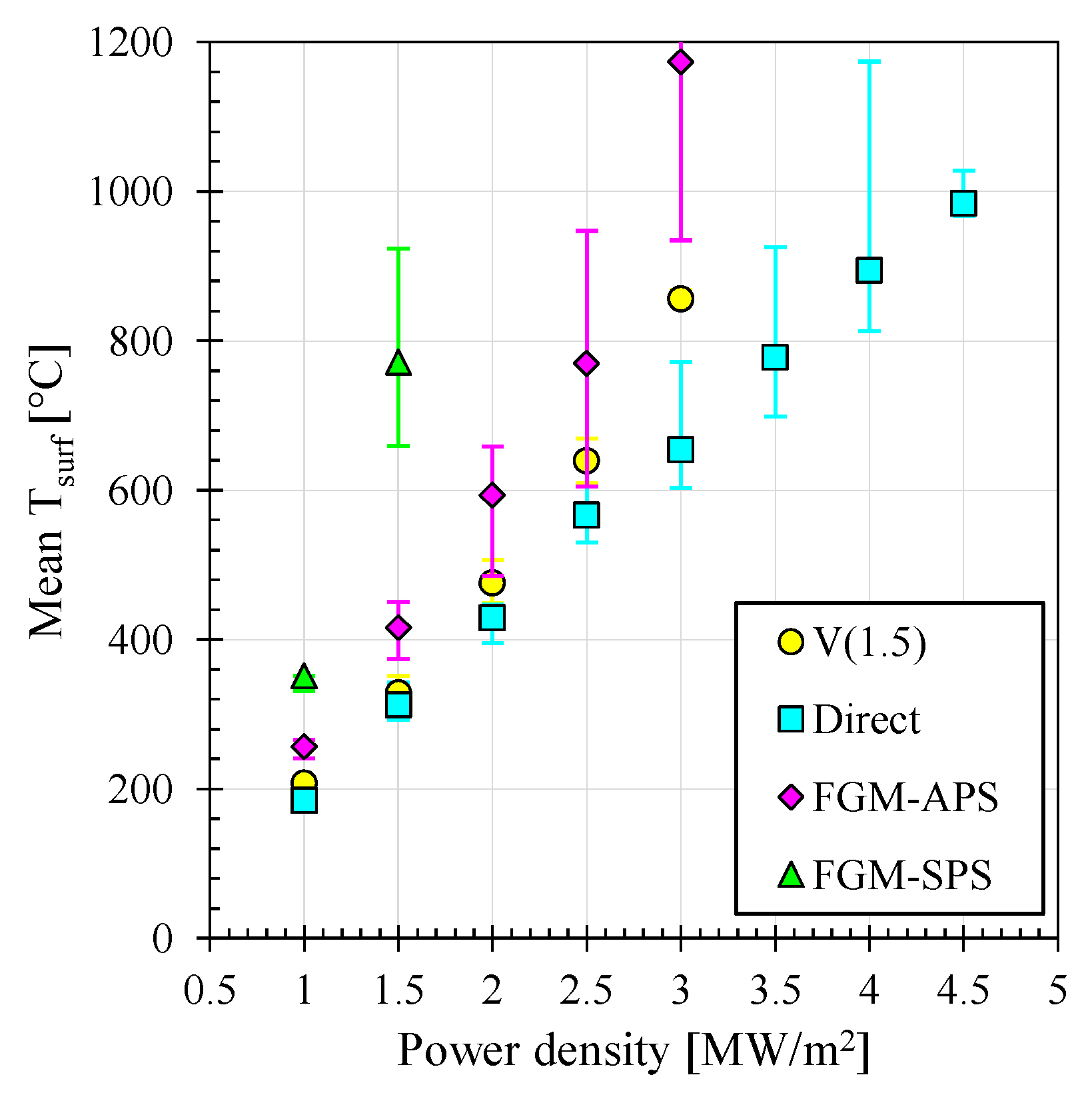
The average Tsurf for the joints with the same configuration was plotted versus the applied heat flux in Figure 5, from which several inferences can be made. First, all joints exhibited a nearly linear progression. The FGM-APS joint showed slightly higher temperatures and deviated from the linear progression at 3.0 MW/m2, indicating signs of degradation, as discussed above. Second, the FGM-APS joint displayed higher temperatures than the V(1.5) joint due to the lower thermal conductivity of its interlayer. The thermal conductivity of the interlayer of FGM-APS joint, which was a combined V-filler and plasma sprayed 25W, 50W, and 75W composites, was approximately 20 W/m·K, as calculated from the literature [7]. This is lower than the thermal conductivity of V, which is 31 W/m·K [16]. Third, and interestingly, the FGM-SPS unexpectedly exhibited the highest temperatures compared to the other joints. The thermal conductivity of the interlayer of the FGM-SPS joint, which consisted of sintered 25W, 50W, and 75W composites presented over one another, was approximately 46 W/m·K, as calculated from the literature [9]. However, even with this higher thermal conductivity, the joint showed higher surface temperatures due to poor metallurgical bonding of the W-tile and the FGM, as can be seen in Figure S2 in Supplementary Information, which hindered the heat removal.
3.2. Post-Mortem Analysis
In the FGM-SPS joint, the failure occurred at the bond seam between the W-tile and the sintered FGM (see Supplementary Materials). This outcome was expected due to imperfect bonding between the W-tile and the topmost layer of the FGM. Similarly, in the V(1.5) joint, failure occurred at the bond seam between the W-tile and V, mostly within V close to the bond seam. In the FGM-APS joint displayed a different failure pattern. Firstly, and primarily, macrocracks were observed inside the plasma sprayed 75W layer and within the V-filler. This was due to the poor mechanical and thermophysical properties of the plasma sprayed composites, as mentioned by Ganesh et al. [7]. Secondly, in some areas, failure occurred between the bond seam of the W-tile and the V-filler. In the directly bonded reference joint, there was only one bonding seam near which the failure took place.
4. Discussion
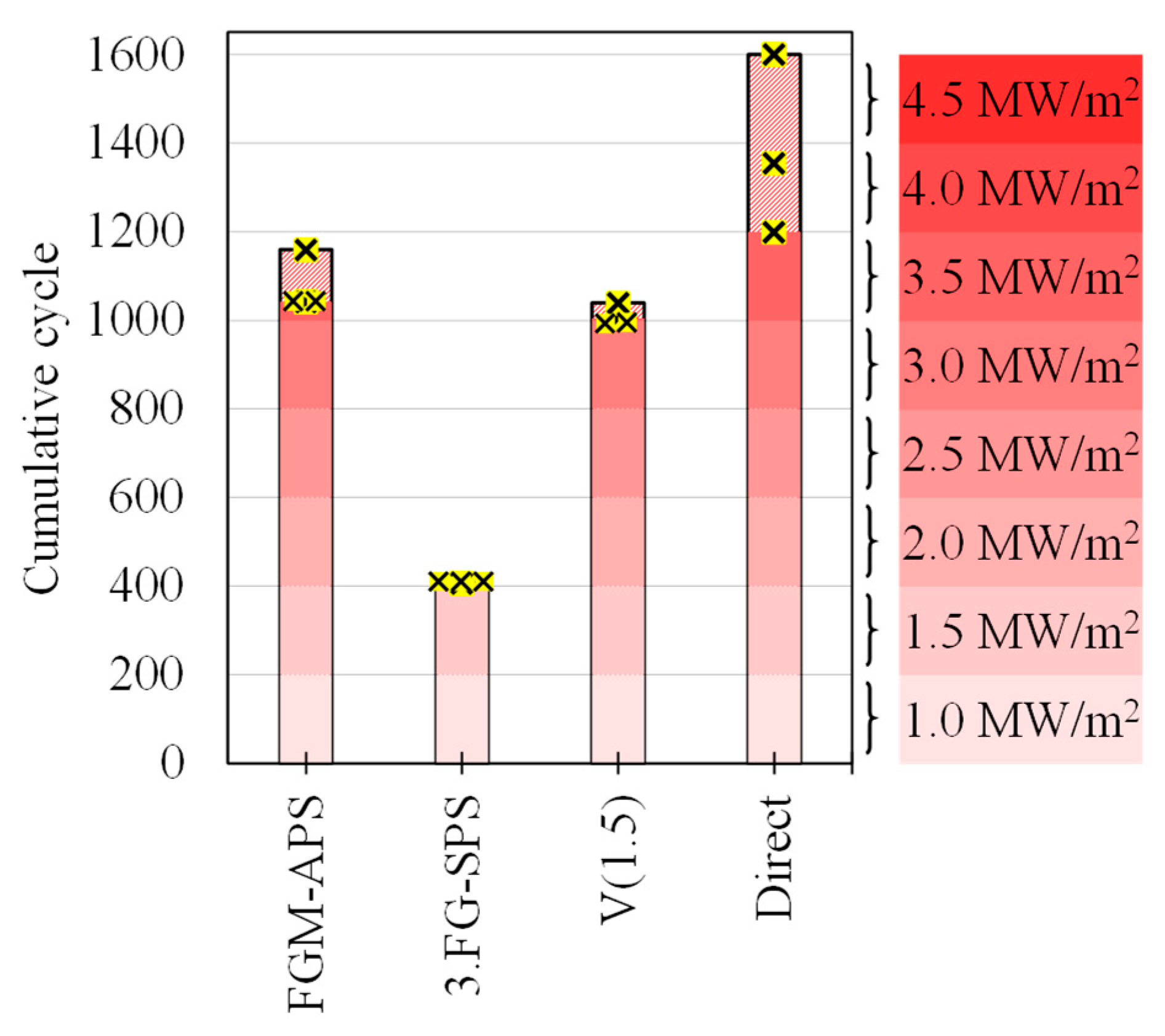
The lifetime of each joining concept, plotted against the cumulative number of the cycles for easy comparison, is shown in Figure 6. Based on this, several inferences can be made. First, it was determined in our previous studies that the layers of atmospheric plasma sprayed FGM have worse mechanical properties (brittle and low toughness) and poor thermal conductivity compared to that of spark plasma sintered FGM [7,9]. Despite this fact, the graded joint featuring atmospheric plasma sprayed FGM showed a far better lifetime compared to the joint with sintered FGM. The reason for this was likely the presence of a ductile auxiliary material that bonds the W-tile and the plasma sprayed FGM better than the direct bonding of the W-tile and sintered FGM. This implies an important phenomenon: the lifetime is primarily dependent on the degree on bonding between the W-tile and the FGM, and the properties of the FGM are beneficial but not crucial.
Second, the prime location of the failure in the graded joint containing sintered FGM was the bond seam between the W-tile and the FGM. This was indicated by the FE numerical study by Heuer et al. [4], which showed that the primary location of the normal stress perpendicular to the bonding seam, which is responsible for the debonding, is essentially at the corner of the joint, particularly at W-FGM interface. The failure at this location suggests that this was the weakest site, and the quality of bonding between the W-tile and the FGM has a major influence on the lifetime of the graded joint. This further implies that it is beneficial to have a ductile auxiliary material at this interface for improving the lifetime of the joints. Two studies on the development of advanced divertor concepts for a future fusion reactor also support this postulation. For example, in one study by Richou et al. [17], W/Cu-FGM was investigated. The bonding seam between the W/Cu-FGM and the W monoblock contained an approximately 20 μm-thin Cu layer. In another similar study by Müller et al. [18], the bonding seam between W and the W/Cu-composite contained a 10 μm-thin Cu layer. However, it is too early to conclude that a ductile auxiliary layer is necessary and applicable to the W/steel-FGM system.
Third, the joint featuring only a V interlayer did not have a longer lifetime than the reference joint. As summarized by Heuer et al. [19], there has been one conceptual study on the insertion of a V interlayer between W and steel for the FW due to its several advantages, including a ductile nature, CTE between that of W and steel, the ability to metallurgically bond well with W by forming a solid solution, and low activation after neutron irradiation. To date, no study has reported the HHF testing of such a joint. The present study filled this gap. The FGM-APS and the V(1.5) showed almost the same lifetime; however, the V(1.5) showed no signs of degradation/local overheating prior to its ultimate failure.
Fourth, it should be noted that the lifetime of the joints tested in this work cannot be directly taken as the service life of an actual FW component in a fusion reactor for the following reasons: (a) in this test, copper was used between the steel and coolant, while in an actual FW, a coolant would flow through the steel; (b) the coolant in this test was flowing at 20 °C, while in the actual FW coolant would flow at approximately 300 °C; (c) the geometry of the actual FW would be significantly different than the geometry tested in this work. Therefore, the heat fluxes in this test should not be confused with the heat fluxes in the actual FW. For instance, the directly bonded reference joint survived a heat flux of 3.5 MW/m2 in this work (see Figure 6), but a directly bonded FW component in an actual reactor would not survive a 3.5 MW/m2 loading. Nevertheless, the direct comparison in this study allows for an assessment of which joining technologies are worth pursuing and developing for future qualification tests.
Finally and interestingly, the directly bonded reference joint outperformed all of the other technologies tested. It was presumed by many literature sources that the directly bonded joint would fail prematurely, but it was never proved experimentally. As discussed earlier, Hirose et al. [10] demonstrated the successful direct bonding and mentioned that the CA-DB process is a promising approach. Direct joining is indeed the simplest approach, but it may be too early to conclude that direct joining should be the way forward. However, this study provides helpful insights for future studies and suggests that also this simplest approach should not be dismissed lightly.
5. Conclusions
For the FW of a future fusion reactor, two concepts utilizing a graded plasma sprayed interlayer and a graded sintered interlayer between W armor and steel have been investigated using a cyclic HHF benchmark test. The HHF test was performed on small-scale joints by brazing them onto a Cu heat sink. The HHF testing was performed from 1 MW/m2 up to 4.5 MW/m2 loading. Although the study revealed that none of the concepts outperformed a directly bonded reference joint, the test revealed some crucial insight into the successful realization of a graded joint. First, the most important requirement is the bonding between the W and the FGM, and not the properties of the FGM itself. Second, there is a lack of studies regarding the HHF testing of joining concepts. Often, studies only report the mechanical joint strength but not the thermal fatigue response. This gap must be filled in the future. To conclude, it can be stated that for the successful realization of the graded joint featuring the spark plasma sintered FGM, it is vital to develop technology to bond the W and the sintered FGM using a suitable auxiliary material with the following properties: ductile nature, CTE close to that of W and 75W(topmost FGM layer), and forming good bonding with W and the FGM. However, it is too early to state that it is vital to have such a ductile auxiliary material, as the embrittlement of such ductile auxiliary material after neutron irradiation and embrittlement due to hydrogen during the operation of the fusion reactor could change the result. This should be taken into account in future comparative studies. Third, this study demonstrated that the CA-DB technology has the potential to produce direct W-steel joints that can survive relevant thermal loading cycles. However, the issues of upscaling and industrial production of components using CA-DB needs to be addressed. Finally, and importantly, the data relating to the reference joint will be helpful in the future for comparing newer joining technologies.
Supplementary Materials
The following supporting information can be downloaded at: https://www.mdpi.com/article/10.3390/en16093664/s1, Figure S1: Cross-sectional image of the manufactured FGM-APS joint; Figure S2: Cross-sectional image of the manufactured FGM-SPS joint; Figure S3: Cross-sectional image of the V(1.5) joint; Figure S4: Cross-sectional image of the Direct joint; Figure S5: Performance and lifetime of V(0.3) and V(0.8) joint; Figure S6: Post-mortem SEM investigation of FGM-APS joint; Figure S7: Post-mortem SEM investigation of FGM-SPS joint; Figure S8: Post-mortem SEM investigation of V(1.5) joint; Figure S9: Post-mortem SEM investigation of Direct joint.
Author Contributions
Conceptualization, V.G. and D.D.-G.; methodology, D.D.-G.; formal analysis, D.D.-G.; investigation, V.G., D.D.-G. and M.V.; resources, M.B.; writing—original draft preparation, V.G.; writing—review and editing, V.G., D.D.-G. and J.M.; supervision, D.D.-G. and C.L.; project administration, C.L.; funding acquisition, D.D.-G. and C.L. All authors have read and agreed to the published version of the manuscript.
Funding
This work has been carried out within the framework of the EUROfusion Consortium, funded by the European Union via the Euratom Research and Training Programme (Grant Agreement No 101052200—EUROfusion). The views and opinions expressed are those of the author(s) only and do not necessarily reflect those of the European Union or the European Commission. Neither the European Union nor the European Commission can be held responsible for them.
Data Availability Statement
Not applicable.
Acknowledgments
The authors would like to thank Thomas Koppitz for assistance in brazing, Thorsten Tietz and Karsten Dominiczak for assistance with JUDITH 2 operation, and Jan Coenen, Gerald Pintsuk, and Marius Wirtz (the project leaders).
Conflicts of Interest
The authors declare no conflict of interest.
References
- Barrett, T.R.; Ellwood, G.; Pérez, G.; Kovari, M.; Fursdon, M.; Domptail, F.; Kirk, S.; McIntosh, S.C.; Roberts, S.; Zheng, S.; et al. Progress in the engineering design and assessment of the European DEMO first wall and divertor plasma facing components. Fusion Eng. Des. 2016, 109–111, 917–924. [Google Scholar] [CrossRef]
- Catanzaro, I.; Arena, P.; Basile, S.; Bongiovì, G.; Chiovaro, P.; Del Nevo, A.; Di Maio, P.A.; Forte, R.; Maione, I.A.; Vallone, E. Structural assessment of the EU-DEMO WCLL Central Outboard Blanket segment under normal and off-normal operating conditions. Fusion Eng. Des. 2021, 167, 112350. [Google Scholar] [CrossRef]
- Arena, P.; Del Nevo, A.; Moro, F.; Noce, S.; Mozzillo, R.; Imbriani, V.; Giannetti, F.; Edemetti, F.; Froio, A.; Savoldi, L.; et al. The DEMO Water-Cooled Lead–Lithium Breeding Blanket: Design Status at the End of the Pre-Conceptual Design Phase. Appl. Sci. 2021, 11, 11592. [Google Scholar] [CrossRef]
- Heuer, S.; Weber, T.; Pintsuk, G.; Coenen, J.W.; Matejicek, J.; Linsmeier, C. Aiming at understanding thermo-mechanical loads in the first wall of DEMO: Stress-strain evolution in a Eurofer-tungsten test component featuring a functionally graded interlayer. Fusion Eng. Des. 2018, 135, 141–153. [Google Scholar] [CrossRef]
- Qu, D.; Basuki, W.W.; Aktaa, J. Numerical assessment of functionally graded tungsten/EUROFER coating system for first wall applications. Fusion Eng. Des. 2015, 98–99, 1389–1393. [Google Scholar] [CrossRef]
- Kavka, T.; Matejicek, J.; Ctibor, P.; Hrabovsky, M. Spraying of metallic powders by hybrid gas/water torch and the effects of inert gas shrouding. J. Therm. Spray Technol. 2012, 21, 695–705. [Google Scholar] [CrossRef]
- Ganesh, V.; Dorow-Gerspach, D.; Heuer, S.; Matejicek, J.; Vilemova, M.; Bram, M.; Coenen, J.W.; Wirtz, M.; Pintsuk, G.; Theisen, W.; et al. Manufacturing of W-steel joint using plasma sprayed graded W/steel-interlayer with current assisted diffusion bonding. Fusion Eng. Des. 2021, 172, 112896. [Google Scholar] [CrossRef]
- Matejicek, J.; Boldyryeva, H. Processing and temperature-dependent properties of plasma-sprayed tungsten–stainless steel composites. Phys. Scr. 2009, T138, 14041. [Google Scholar] [CrossRef]
- Ganesh, V.; Dorow-Gerspach, D.; Bram, M.; Coenen, J.W.; Wirtz, M.; Pintsuk, G.; Theisen, W.; Linsmeier, C. Processing and properties of sintered W/steel composites for the first wall of future fusion reactor. JNE 2023, 4, 177–192. [Google Scholar] [CrossRef]
- Hirose, T.; Shiba, K.; Ando, M.; Enoeda, M.; Akiba, M. Joining technologies of reduced activation ferritic/martensitic steel for blanket fabrication. Fusion Eng. Des. 2006, 81, 645–651. [Google Scholar] [CrossRef]
- De Prado, J.; Sanchez, M.; Wirtz, M.; Pintsuk, G.; Du, J.; Linke, J.; Urena, A. Impact of thermal fatigue on W–W brazed joints for divertor components. J. Mater. Process. Technol. 2018, 252, 211–216. [Google Scholar] [CrossRef]
- De Prado, J.; Sanchez, M.; Wirtz, M.; Pintsuk, G.; Du, J.; Linke, J.; Urena, A. High heat flux performance of W-Eurofer brazed joints. J. Nucl. Mater. 2018, 499, 225–232. [Google Scholar] [CrossRef]
- Casalegno, V.; Perero, S.; Girman, V.; Sedlák, R.; Scarpellini, A.; Dorow-Gerspach, D.; Heuer, S.; Ferraris, M. W/Fe co-sputtered layers for tungsten to steel joints. Nucl. Mater. Energy 2023, 35, 101421. [Google Scholar] [CrossRef]
- Schmidt, A.; Bürger, A.; Dominiczak, K.; Keusemann, S.; Loewenhoff, T.; Linke, J.; Roedig, M.; Thomser, C. High heat flux testing of components for future fusion devices by means of the facility JUDITH 2. In Proceedings of the International Conference on High-Power Electron Beam Technology, International Conference on High-Power Electron Beam Technology, Reno, NV, USA, 24–26 October 2010; Curran: Red Hook, NY, USA, 2011. ISBN 9781617823992. [Google Scholar]
- Maviglia, F.; Bachmann, C.; Federici, G.; Franke, T.; Siccinio, M.; Albanese, R.; Ambrosino, R.; Arter, W.; Bonifetto, R.; Calabrò, G.; et al. Integrated design strategy for EU-DEMO first wall protection from plasma transients Fusion Engineering and Design 177 (2022) 113067. Fusion Eng. Des. 2022, 178, 113125. [Google Scholar] [CrossRef]
- Touloukian, Y.S.; Powell, R.W.; Ho, C.Y.; Klemens, P.G. Thermophysical Properties of Matter—The TPRC Data Series: Volume 1. Thermal Conductivity-Metallic Elements and Alloys; Springer: Boston, MA, USA, 1970; ISBN 978-1-4615-9602-8. [Google Scholar]
- Richou, M.; Gallay, F.; Böswirth, B.; Chu, I.; Dose, G.; Greuner, H.; Kermouche, G.; Lenci, M.; Loewenhoff, T.; Maestracci, R.; et al. Performance assessment of thick W/Cu graded interlayer for DEMO divertor target. Fusion Eng. Des. 2020, 157, 111610. [Google Scholar] [CrossRef]
- Müller, A.V.; Böswirth, B.; Cerri, V.; Greuner, H.; Neu, R.; Siefken, U.; Visca, E.; You, J.-H. Application of tungsten–copper composite heat sink materials to plasma-facing component mock-ups. Phys. Scr. 2020, T171, 14015. [Google Scholar] [CrossRef]
- Heuer, S.; Coenen, J.W.; Pintsuk, G.; Matejicek, J.; Vilemova, M.; Linsmeier, C. Overview of challenges and developments in joining tungsten and steel for future fusion reactors. Phys. Scr. 2020, T171, 14028. [Google Scholar] [CrossRef]
Figure 1.
Schematic representation of the HHF testing procedure; joints brazed on to Cu modules were installed in JUDITH 2 with connected cooling circuits.
Figure 1.
Schematic representation of the HHF testing procedure; joints brazed on to Cu modules were installed in JUDITH 2 with connected cooling circuits.

Figure 2.
(Left) Photograph of the joints before the HHF testing. (Right) Photograph of the joints after the HHF testing (note: A, B, C refer to sample labelling and * refers to other concepts which were tested in the same experimental campaign but not related to this work. In addition to the V(1.5) joint, we tested two more joints featuring V interlayers of the following thicknesses: 0.3 mm, known as the V(0.3) joint, and 0.8 mm, known as the V(0.8) joint. These results are provided in the supplementary materials).

Figure 3.
History of Tsurf over the entire HHF testing starting from 1 MW/m2 for the following joints: (a) FGM-APS, (b) FGM-SPS, (c) direct, (d) V(1.5) (Note: A, B, C is the sample labelling).
Figure 3.
History of Tsurf over the entire HHF testing starting from 1 MW/m2 for the following joints: (a) FGM-APS, (b) FGM-SPS, (c) direct, (d) V(1.5) (Note: A, B, C is the sample labelling).

Figure 4.
Steady-state surface temperature of W-tile: (a) first cycle at 1.5 MW/m2 loading, (b) first cycle at 2 MW/m2 loading, (c) first cycle at 2.5 MW/m2 loading, and (d) 200th cycle at 2.5 MW/m2 loading.
Figure 4.
Steady-state surface temperature of W-tile: (a) first cycle at 1.5 MW/m2 loading, (b) first cycle at 2 MW/m2 loading, (c) first cycle at 2.5 MW/m2 loading, and (d) 200th cycle at 2.5 MW/m2 loading.

Figure 5.
Evolution of mean Tsurf for all investigated joining concepts at each particular heat flux.
Figure 5.
Evolution of mean Tsurf for all investigated joining concepts at each particular heat flux.

Figure 6.
Lifetime of each joining concepts (Note: ![Energies 16 03664 i005]() represents the lifetime of each sample and
represents the lifetime of each sample and ![Energies 16 03664 i006]() represents the scatter).
represents the scatter).
 represents the lifetime of each sample and
  represents the scatter).
Figure 6.
Lifetime of each joining concepts (Note: ![Energies 16 03664 i005]() represents the lifetime of each sample and
represents the lifetime of each sample and ![Energies 16 03664 i006]() represents the scatter).
represents the scatter).
represents the lifetime of each sample and represents the scatter).

Table 1.
Overview of the different joining concepts tested under HHF loading, along with shorter nomenclatures and the joining parameters for every concept. Three samples from each joining concepts were included in the testing.
Table 1.
Overview of the different joining concepts tested under HHF loading, along with shorter nomenclatures and the joining parameters for every concept. Three samples from each joining concepts were included in the testing.
| Configuration | SEM Image | Nomenclature | Manufacturing Route | Joining Parameter | Interlayer Thickness (mm) |
|---|---|---|---|---|---|
| Graded joint featuring plasma sprayed FGM |  | FGM-APS | Modified atmospheric plasma spraying and joining by current assisted diffusion bonding | 1000 °C 30 min 50 MPa | V: 0.21 |
| 75W: 0.40 | |||||
| 50W: 0.39 | |||||
| 25W: 0.42 | |||||
| Graded joint featuring sintered FGM |  | FGM-SPS | Spark plasma sintering | 1000 °C 5 min 125 MPa | 75W: 0.59 |
| 50W: 0.50 | |||||
| 25W: 0.48 | |||||
| Joint featuring V interlayer |  | V(1.5) | Current assisted diffusion bonding | 1000 °C 30 min 20 MPa | V: 1.50 |
| Reference joint directly bonded |  | Direct | Current assisted diffusion bonding | 1000 °C 15 min 20 MPa | - |
Table 2.
Planned loading scenario for the benchmarking of the joining concepts.
| Heat Flux (MW/m2) | No. of Cycles | Cumulative No. of Cycles 1 |
|---|---|---|
| 1.0 | 200 | 200 |
| 1.5 | 200 | 400 |
| 2.0 | 200 | 600 |
| 2.5 | 200 | 800 |
| 3.0 | 200 | 1000 |
| 3.5 | 200 | 1200 |
| 4.0 | 200 | 1400 |
| 4.5 | 200 | 1600 |
1 Cumulative number of cycles refers to the total number of cycles performed from the beginning.
Disclaimer/Publisher’s Note: The statements, opinions and data contained in all publications are solely those of the individual author(s) and contributor(s) and not of MDPI and/or the editor(s). MDPI and/or the editor(s) disclaim responsibility for any injury to people or property resulting from any ideas, methods, instructions or products referred to in the content. |
© 2023 by the authors. Licensee MDPI, Basel, Switzerland. This article is an open access article distributed under the terms and conditions of the Creative Commons Attribution (CC BY) license (https://creativecommons.org/licenses/by/4.0/).
Share and Cite
MDPI and ACS Style
Ganesh, V.; Dorow-Gerspach, D.; Bram, M.; Linsmeier, C.; Matejicek, J.; Vilemova, M. High Heat Flux Testing of Graded W-Steel Joining Concepts for the First Wall. Energies 2023, 16, 3664. https://doi.org/10.3390/en16093664
AMA Style
Ganesh V, Dorow-Gerspach D, Bram M, Linsmeier C, Matejicek J, Vilemova M. High Heat Flux Testing of Graded W-Steel Joining Concepts for the First Wall. Energies. 2023; 16(9):3664. https://doi.org/10.3390/en16093664
Chicago/Turabian StyleGanesh, Vishnu, Daniel Dorow-Gerspach, Martin Bram, Christian Linsmeier, Jiri Matejicek, and Monika Vilemova. 2023. "High Heat Flux Testing of Graded W-Steel Joining Concepts for the First Wall" Energies 16, no. 9: 3664. https://doi.org/10.3390/en16093664
Note that from the first issue of 2016, this journal uses article numbers instead of page numbers. See further details here.