Entropy Production in an Elementary, Light Driven Micro-Machine
 Stuart J. Box
 Michael P. Allen
 David B. Phillips
 Stephen H. Simpson
- 1H.H. Wills Physics Laboratory, University of Bristol, Bristol, United Kingdom
- 2Department of Physics, University of Warwick, Coventry, United Kingdom
- 3Department of Physics and Astronomy, University of Exeter, Exeter, United Kingdom
- 4Institute of Scientific Instruments of the Czech Academy of Science, Brno, Czech Republic
We consider the basic, thermodynamic properties of an elementary micro-machine operating at colloidal length scales. In particular, we track and analyze the driven stochastic motion of a carefully designed micro-propeller rotating unevenly in an optical tweezers, in water. In this intermediate regime, the second law of macroscopic thermodynamics is satisfied only as an ensemble average, and individual trajectories can be temporarily associated with decreases in entropy. We show that our light driven micro-propeller satisfies an appropriate fluctuation theorem that constrains the probability with which these apparent violations of the second law occur. Implications for the development of more complex micro-machines are discussed.
1. Introduction
Advances in micro-fabrication techniques enable the manufacture of finely structured objects with ever greater precision [1]. As a consequence, increasingly sophisticated micro-machines are being developed [2–4] to perform a variety of previously unrealisable tasks in the colloidal regime. Examples include controlled transport, micro-fluidics, pumping and mixing [5–9], sensing [10], or even hydrodynamic manipulation [11]. More recently, self-organizing, dynamically reconfigurable and self-propelled micro-machines have been exhibited [12–15]. Quantitatively describing the behavior of machines at these length scales is not trivial. Classical thermodynamics was developed, in part, to help optimize the efficiency of conventional machines. This framework, however, is inadequate for the colloidal regime where the energy flows that drive the machines are comparable in size to stochastic thermal fluctuations. In this article, we analyze the influence of thermal fluctuations on an elementary micro-machine, in this case a light driven micro-propeller or light-mill, observing that they are constrained by an appropriate fluctuation theorem [16]. In doing so, we underscore the usefulness of applying the principles of stochastic thermodynamics [17] to the design of novel micro-machines.
As with biological analogues such as molecular motors [18], artificial micro-machines operate in an intermediate thermodynamic regime. Conventional machines, working at every-day length scales, conform to the laws of classical, macroscopic thermodynamics where physical processes are strictly irreversible and associated with increasing disorder, or entropy. In contrast, dynamical motion at microscopic length scales is governed by time symmetric equations of motion. The thermodynamics of micro-machines are neither purely reversible nor completely irreversible and the second law of thermodynamics, which prohibits entropy from decreasing with time, appears not as an absolute law, but as a limiting case, emerging only for sufficiently large systems, over sufficient time intervals [17, 19]. For micro-machines, working in the colloidal regime, individual trajectories can be associated with decreasing entropy for finite periods of time. The relative probability of observing such a trajectory is constrained by the fluctuation theorem (FT), the term really applying to a family of theorems, and decreases exponentially with time, with the second law restored in the limit either of long times or large system sizes. For a general system the FT takes the following form:
where
Equation 1 is commonly referred to as the transient or detailed FT (DFT) to distinguish it from the integrated version,
where
We wish to confirm appropriate versions of the fluctuation theorems, Eqs 1 and 2 for an elementary micro-machine. Previous tests of the FT involve dragging spherical beads through water with optical traps [20, 21] under various conditions [22]. In these studies, a colloidal bead is dragged in a straight line, with a force that does not depend explicitly on position. By contrast, we use an autonomous micro-machine, with a more complex geometry and force profile. As will become clear, this increase in complexity gives rise to a number of experimental challenges, especially those relating to the design of our micro-machine and to the tracking of its motion.
Our chosen machine is a simple, light driven propeller or light-mill, which we fabricate using two-photon polymerization [23]. We track its motion as it rotates in a laser trap, showing that it conforms to an appropriate FT. The propeller has been carefully designed so that it rotates slowly about its axis, allowing its motion to be tracked with sufficient accuracy and resolution to observe trajectories with temporarily decreasing entropy. Small, natural asymmetries in the system cause the axial torque to vary strongly with orientation, so that the rotational motion is highly uneven. For the rotor used in this study, the ratio of the maximum to minimum torque is
In the following sections we review the necessary theoretical background, which closely follows the work of Speck, Seifert et al. [22], describe the design and fabrication of the rotor and the experimental procedure. We next present tests of the detailed and integrated forms of the rotational FT. We comment on the small discrepancies between theory and experiment and conclude with a discussion of the implications for the optimal design of future micro-machines.
2. Theoretical Background
We consider the over-damped motion of a Brownian propeller or rotor, rotating about a fixed axis in water. This motion is described by the Langevin equation,
where ϕ is the orientation of the rotor and
Thus, we focus on axial rotations, assuming that the motion of all other degrees of freedom are negligible or independent. Qualitative features of the motion follow from a consideration of the impulses, I, delivered to the rotor over a finite time interval,
In other words, for very small
where
As mentioned above, the torque,
Here,
where the integral in Eq. 10 is evaluated by writing the torque as the derivative of the potential in Eq. 9, and
and the change in the system entropy,
where
The principles described above provide us with a simple way of testing the rotational fluctuation theorem for a driven micro-propeller. First we measure the steady state orientation distribution,
3. Propeller Design and Fabrication
Testing the rotational FTs described above places some demanding constraints on the design and behavior of our micro-propeller. It must exhibit three key characteristics. 1) The propeller should rotate about a single fixed axis, with minimal fluctuations in the orientation of the axis. 2) It should rotate slowly enough for the short term, entropy consuming trajectories to be accurately resolved by the available technology. Finally, 3) its shape should facilitate accurate tracking of its orientation. We discuss each of these issues in more detail below.
(1) Axis stability: Elongated, dielectric objects tend to align themselves with the axis of optical beams [30]. The stability of the rotation axis of a micro-propeller is therefore promoted by providing it with a long, sturdy central spindle.
(2) Rotation rate: Equation 6 allows us to find a crude estimate of the rotation rate required to observe entropy consuming trajectories, i.e., we require
(3) Tracking: Finally, it must be possible to track the orientation of the propeller with as much angular precision as possible. To do this, we add microspheres to the ends of the rotor arms, and make use of the established methods for high precision sphere tracking [36]. The orientation of the propeller can then be accurately retrieved from measurements of the sphere positions.
With these principles in mind, we arrived at the following final design, shown in Figure 1.
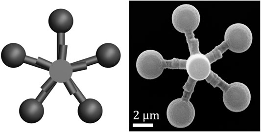
FIGURE 1. The micropropeller used in the experiment. (Left) Schematic of the design, rendered using POV-Ray, (right) SEM image of the microfabricated (two-photon polymerization) propeller used in the experiment.
We fabricate micro-propellers using two-photon polymerization. To implement the geometric design shown in Figure 1 (left), we use custom software (LabVIEW) to generate an instruction file to control the path of a laser beam in a two-photon polymerization machine (Photonic Professional, Nanoscribe). By specifying the beam path directly, rather than relying on slicing software to automatically generate a path from a CAD file, we retain fine control over the fabrication process. We deposit approximately 20 μL of photoresist material (IP-G 780, Nanoscribe) on a coverslip, and then heat it using a hotplate (100 C for 1 h), following the manufacturer’s instructions for photoresist preparation. We then fabricate many (>50) copies of our micro-propeller design using the two-photon polymerization machine to scan a laser beam through the prepared photoresist according to our custom beam path file. The polymerized material is developed, and unpolymerized material washed away, by submersing the coverslip first in developing fluid (Microposit EC Solvent) for 20 min, followed by isopropanol for 5 min. We move the fabricated micro-propellers into suspension by placing a drop of water (Direct-Q 3 UV, Millipore) on top of them, and then apply mechanical agitation to detach them from the coverslip using a thin wire manipulated by a 3-axis translation stage (ULTRAlign Precision XYZ Linear Stage, Newport), similar to a previously employed method [37, 38]. The suspension is transferred to a custom microscope sample chamber consisting of one microscope slide and three coverslips bonded together (UV Adhesive 81 or 68, Norland) using a pipette, and the remaining volume of the chamber is filled with additional water then sealed with adhesive. This process typically results in around 50–80% of the fabricated micro-propellers being transferred into the microscope sample chamber. The two-photon polymerization and transfer steps are all carried out in a clean room.
4. Experiment
We optically trap one of the micro-propellers inside the sample chamber using a custom-built holographic optical tweezers system, which is similar to a system described elsewhere [39]. The optical tweezers are based around a 1,070 nm laser (YLM-5-LP-SC, IPG Photonics) whose beam is expanded to fill a spatial light modulator, or SLM (XY Series HSP512-1064-DVI, Boulder Nonlinear Systems). The beam is then tightly focused using an oil immersion, 1.4 NA, 100× objective lens (Plan-Apochromat, Zeiss) to form optical trap(s). Relative translation of the sample and optics is achieved with a piezo-based translator (Mipos 140 PL, Piezosystem Jena) along the optical (z) axis, and with a servomotor-based stage (MS2000, ASI) in the orthogonal
We record a high speed (1 kHz) video of a trapped and rotating micro-propeller using a custom LabVIEW program to acquire images from the system’s camera. The fast frame rate is achieved by i) reducing the active area of the camera to the minimum needed to view the propeller, ii) use of a signal generator (33220A, Agilent) to trigger the frame grabber, and iii) use of a circular buffer in software that losslessly transfers acquired images to an SSD drive (HyperX SH100S3/120G, Kingston). In our set up, the frame rate is limited by illumination intensity and control over the camera’s exposure time.
Data analysis is performed offline, starting by extracting the position of the micro-propeller in each frame of the video using an additional custom LabVIEW program. We first find the Cartesian position of each of the five spheres on the micro-propeller, using a symmetry transform tracking library, taken from the Red Tweezers software [36, 40]. The propeller’s orientation, ϕ, can then be defined by the Cartesian position of one of the spheres and the position of the propeller’s center. The center is calculated in each frame as the average of the positions of all five spheres.
We record video of a rotating micro-propeller for a period of 15 min, equivalent to approximately 175 complete rotations, and extract the orientation in each frame as described above. The steady state probability distribution,
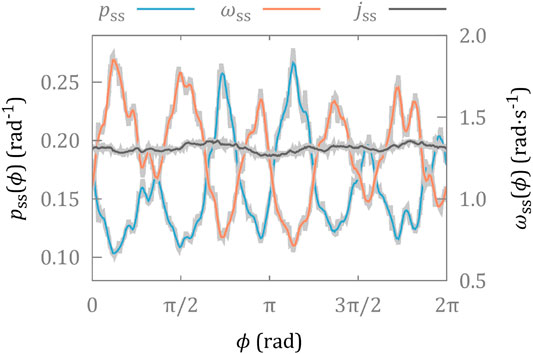
FIGURE 2. Steady state distributions of the orientation,
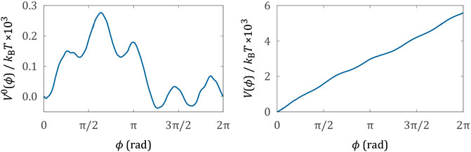
FIGURE 3. Conservative (left hand side) and total potentials (right hand side).
Finally, we investigate total change in entropy over different time scales. We choose an interval, t, and split the time series of micro-propeller orientations from the experiment into
Figure 4 shows histograms of entropy change,
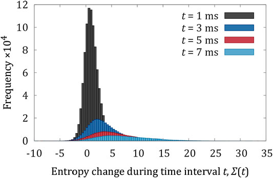
FIGURE 4. Evolution of the distribution of entropy change for a series of increasing time periods.
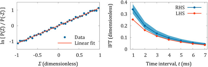
FIGURE 5. Experimental tests of the FT. Left hand side: detailed FT plotted as the natural logarithm of Eq. 1, with best fit straight line with gradient
5. Discussion
We have defined a version of the FT suitable for describing fluctuations of a rudimentary, light driven micro-machine.
The scenario we have considered is somewhat contrived: we had to go to considerable lengths to ensure that we could reliably resolve the behavior of interest. In particular we had to design a propeller that would rotate slowly enough for the transient, entropy consuming trajectories to be accurately measured. The design also minimized motion of the center of mass, and angular fluctuations of the rotation axis, allowing us to eliminate five of the six physical degrees of freedom and focus on the remaining axial rotations. For the detailed FT, Eq. 1 and Figure 5A, the experimental data, which are plotted for the logarithm of Eq. 1 are represented by a straight line, indicating the exponential dependence expected from the FT, however the gradient is higher than expected. In the case of the integrated FT, Eq. 2 and Figure 5B, our measurements tend to under-estimate the entropy changes over very small time intervals, although the agreement becomes more accurate for intervals of longer duration. There are a number of sources of error including image blur and fluctuations in the rotation axis of the micro-propeller. Both of these factors are more significant for short time intervals. In the first case, each video image does not represent an instantaneous moment, but contains contributions from previous times. This has the effect of low pass filtering the measured rotations relative to actual rotations. Tilting of the rotation axis adds a small error to the measured displacement of each tracking sphere, when projected onto a fixed horizontal plane. In addition the effects of data smoothing (Figure 2) will be more significant for shorter intervals.
Nevertheless, the essential features are qualitatively reproduced. For short time intervals, entropy consuming trajectories occur with substantially higher probability, and this probability decreases exponentially as the duration of the time interval increases.
Although it was not straight forward to observe and quantify this behavior, we note that fluctuations influence the efficiency and precision of micro-machines whether they are measured or not. The concepts described in this article, and in the many articles devoted to both the fundamental theory, and to applications in biology, are directly relevant to the growing field of artificial micro-machines [2, 3]. This will become increasingly more true as we try to design increasingly small machines. Indeed, the analysis of the micro-propeller is somewhat simplified by the fact that the underlying potential (Eq. 9; Figure 3) is many times greater than
Data Availability Statement
The raw data supporting the conclusions of this article will be made available by the authors, without undue reservation.
Author Contributions
SB designed and fabricated micro-propellers with support from DP, and performed all experiments, data analysis and figure preparation. SS supervised the project with theoretical support from MA. SS wrote the article with input from all authors.
Funding
SS was supported by the Czech Science Foundation (GA19-17765S) and the European Regional Development Fund (CZ.02.1.01/0.0/0.0/15_003/0000476). SB acknowledges funding from the EPSRC and DP thanks the Royal Academy of Engineering for financial support.
Conflict of Interest
The authors declare that the research was conducted in the absence of any commercial or financial relationships that could be constructed as a potential conflict of interest.
Acknowledgments
The authors are grateful to Prof. John Rarity for the opportunity to use his two-photon polymerization apparatus, and to Prof. Mervyn Miles for the use of his optical tweezers. This work was conducted in the Bristol Center for Nanoscience and Quantum Information.
References
1. LaFratta CN, Baldacchini T. Two-photon polymerization metrology: characterization methods of mechanisms and microstructures. Micromachines. (2017). 8:101. doi:10.3390/mi8040101.
3. Xu Q. Micromachines for biological micromanipulation.. Berlin, Germany: Springer International Publishing (2018).
4. Andrew PK, Williams MAK, Avci E. Optical micromachines for biological studies. Micromachines. (2020). 11:192. doi:10.3390/mi11020192.
5. Hong Y, Diaz M, Córdova-Figueroa UM, Sen A. Light-driven titanium-dioxide-based reversible microfireworks and micromotor/micropump systems. Adv Funct Mater. (2010). 20:1568–76. doi:10.1002/adfm.201000063.
6. Chen H, Zhao Q, Du X. Light-powered micro/nanomotors. Micromachines. (2018). 9:41. doi:10.3390/mi9020041.
7. Huang TY, Sakar MS, Mao A, Petruska AJ, Qiu F, Chen XB, et al. 3D printed microtransporters: compound micromachines for spatiotemporally controlled delivery of therapeutic agents. Adv Mater. (2015). 27:6644–50. doi:10.1002/adma.201503095.
8. Swartzlander GA, Peterson TJ, Artusio-Glimpse AB, Raisanen AD. Stable optical lift. Nat Photonics. (2011). 5:48–51. doi:10.1038/NPHOTON.2010.266.
9. Simpson SH, Hanna S, Peterson TJ, Swartzlander GA. Optical lift from dielectric semicylinders. Opt Lett. (2012). 37:4038–40. doi:10.1364/OL.37.004038.
10. Phillips DB, Padgett MJ, Hanna S, Ho YLD, Carberry DM, Miles MJ, et al. Shape-induced force fields in optical trapping. Nat Photonics. (2014). 8:400–5. doi:10.1038/nphoton.2014.74.
11. Butaite UG, Gibson GM, Ho YLD, Taverne M, Taylor JM, Phillips DB. Indirect optical trapping using light driven micro-rotors for reconfigurable hydrodynamic manipulation. Nat Commun. (2019). 10:1215. doi:10.1038/s41467-019-08968-7.
12. Cui J, Huang TY, Luo Z, Testa P, Gu H, Chen XZ, et al. Nanomagnetic encoding of shape-morphing micromachines. Nature. (2019). 575:164–8. doi:10.1038/s41586-019-1713-2.
13. Alapan Y, Yigit B, Beker O, Demirörs AF, Sitti M. Shape-encoded dynamic assembly of mobile micromachines. Nat Mater. (2019). 18:1244–51. doi:10.1038/s41563-019-0407-3.
14. Huang HW, Sakar MS, Petruska AJ, Pané S, Nelson BJ. Soft micromachines with programmable motility and morphology. Nat Commun. (2016). 7:12263. doi:10.1038/ncomms12263.
15. Tottori S, Zhang L, Qiu F, Krawczyk KK, Franco-Obregón A, Nelson BJ. Magnetic helical micromachines: fabrication, controlled swimming, and cargo transport. Adv Mater. (2012). 24:811–6. doi:10.1002/adma.201103818.
16. Evans D, Searles D. The fluctuation theorem. Adv Phys. (2002). 51:1529–85. doi:10.1080/00018730210155133.
17. Seifert U. Stochastic thermodynamics, fluctuation theorems and molecular machines. Rep Prog Phys. (2012). 75:126001. doi:10.1088/0034-4885/75/12/126001.
18. Hoffmann PM. How molecular motors extract order from chaos (a key issues review). Rep Prog Phys. (2016). 79:032601. doi:10.1088/0034-4885/79/3/032601.
19. Evans DJ, Searles DJ, Williams SR. Dissipation and the relaxation to equilibrium. J Stat Mech-Theory E. (2009). 24:P07029. doi:10.1088/1742-5468/2009/07/P07029.
20. Reid J, Carberry D, Wang G, Sevick E, Evans D, Searles D. Reversibility in nonequilibrium trajectories of an optically trapped particle. Phys Rev E. (2004). 70:016111. doi:10.1103/PhysRevE.70.016111.
21. Carberry D, Reid J, Wang G, Sevick E, Searles D, Evans D. Fluctuations and irreversibility: an experimental demonstration of a second-law-like theorem using a colloidal particle held in an optical trap. Phys Rev Lett. (2004). 92:140601. doi:10.1103/PhysRevLett.92.140601.
22. Speck T, Blickle V, Bechinger C, Seifert U. Distribution of entropy production for a colloidal particle in a nonequilibrium steady state. Europhys Lett. (2007). 79:30002. doi:10.1209/0295-5075/79/30002.
23. Cumpston B, Ananthavel S, Barlow S, Dyer D, Ehrlich J, Erskine L, et al. Two-photon polymerization initiators for three-dimensional optical data storage and microfabrication. Nature. (1999). 398:51–4. doi:10.1038/17989.
24. Coffey WT, Kalmykov YP, Waldron JT. The Langevin equation.. Singapore: World Scientific Publishing (1996).
25. Van Kampen N. Stochastic processes in physics and chemistry. Amsterdam, Netherlands: Elsevier Science B.V. (1992).
27. Seifert U. Entropy production along a stochastic trajectory and an integral fluctuation theorem. Phys Rev Lett. (2005). 95:040602. doi:10.1103/PhysRevLett.95.040602.
28. Johari GP. Effects of electric field on the entropy, viscosity, relaxation time, and glass formation. J Chem Phys. (2013). 138:154503. doi:10.1063/1.4799268.
29. Carrasco B, de la Torre J. Hydrodynamic properties of rigid particles: comparison of different modeling and computational procedures. Biophys J. (1999). 76:3044–57. doi:10.1016/S0006-3495(99)77457-6.
30. Simpson SH, Hanna S. Stability analysis and thermal motion of optically trapped nanowires. Nanotechnology. (2012). 23:205502. doi:10.1088/0957-4484/23/20/205502.
31. Galajda P, Ormos P. Rotors produced and driven in laser tweezers with reversed direction of rotation. Appl Phys Lett. (2002). 80:4653–5. doi:10.1063/1.1480885.
32. Asavei T, Loke VLY, Barbieri M, Nieminen TA, Heckenberg NR, Rubinsztein-Dunlop H. Optical angular momentum transfer to microrotors fabricated by two-photon photopolymerization. New J Phys. (2009). 11:093021. doi:10.1088/1367-2630/11/9/093021.
33. Brzobohatý O, Arzola AV, Šiler M, Chvátal L, Jákl P, Simpson S, et al. Complex rotational dynamics of multiple spheroidal particles in a circularly polarized, dual beam trap. Opt Express. (2015). 23:7273–87. doi:10.1364/OE.23.007273.
34. Loke VLY, Asavei T, Stilgoe AB, Nieminen TA, Rubinsztein-Dunlop H. Driving corrugated donut rotors with Laguerre–Gauss beams. Opt Express. (2014). 22:19692–706. doi:10.1364/OE.22.019692.
35. Simpson SH, Benito DC, Hanna S. Polarization-induced torque in optical traps. Phys Rev A. (2007). 76:043408. doi:10.1103/PhysRevA.76.043408.
36. Bowman R, Gibson G, Padgett M. Particle tracking stereomicroscopy in optical tweezers: control of trap shape. Opt Express. (2010). 18:11785–90. doi:10.1364/OE.18.011785.
37. Phillips DB, Simpson SH, Grieve JA, Bowman R, Gibson GM, Padgett MJ, et al. Force sensing with a shaped dielectric micro-tool. Europhys Lett. (2012). 99:58004. doi:10.1209/0295-5075/99/58004.
38. Phillips DB, Whyte G, Carberry DM, Hanna S, Miles MJ, Padgett MJ, et al. Fashioning microscopic tools. In: Optical trapping and optical micromanipulation X., 2013 Aug 25-29; San Diego; Vol. 8810, New York, NY: International Society for Optics and Photonics (2013). 881029. doi:10.1117/12.2024230.
39. Gibson G, Carberry DM, Whyte G, Leach J, Courtial J, Jackson JC, et al. Holographic assembly workstation for optical manipulation. J Opt A-Pure Appl Opt. (2008). 10:044009. doi:10.1088/1464-4258/10/4/044009.
40. Bowman RW, Gibson GM, Linnenberger A, Phillips DB, Grieve JA, Carberry DM, et al. “Red Tweezers”: fast, customisable hologram generation for optical tweezers. Comput Phys Commun. (2014). 185:268–73. doi:10.1016/j.cpc.2013.08.008.
41. Box S, Debono L, Phillips DB, Simpson SH Transitional behavior in hydrodynamically coupled oscillators. Phys Rev E. (2015). 91:022916. doi:10.1103/PhysRevE.91.022916.
Keywords: non-equilibrium thermodynamics, Brownian motion, micro-machines, fluctuations, optical tweezers
Citation: Box SJ, Allen MP, Phillips DB and Simpson SH (2020) Entropy Production in an Elementary, Light Driven Micro-Machine. Front. Phys. 8:593122. doi: 10.3389/fphy.2020.593122
Received: 09 August 2020; Accepted: 26 October 2020;
Published: 30 November 2020.
Edited by:
Halina Rubinsztein-Dunlop, The University of Queensland, AustraliaReviewed by:
Timo Nieminen, The University of Queensland, AustraliaCopyright © 2020 Simpson, Box, Allen and Phillips. This is an open-access article distributed under the terms of the Creative Commons Attribution License (CC BY). The use, distribution or reproduction in other forums is permitted, provided the original author(s) and the copyright owner(s) are credited and that the original publication in this journal is cited, in accordance with accepted academic practice. No use, distribution or reproduction is permitted which does not comply with these terms.
*Correspondence: Stephen H. Simpson, simpson@ISIBrno.Cz