
Abstract
High-enthalpy hybrid water/argon-stabilized plasma (WSP-H) torch may be used for efficient deposition of coatings from dry powders, suspensions, and solutions. WSP-H torch was used to deposit two complete thermal barrier coatings (TBCs) with multilayered top-coat. NiCrAlY was used as bond-coat and deposited on nickel-based superalloy substrates. Top-coat consisted of up to three sublayers: (i) yttria-stabilized zirconia (ZrO2-8 wt.%Y2O3-YSZ) deposited from solution, (ii) gadolinium zirconate (Gd2Zr2O7-GZO) deposited from suspension, and (iii) optional yttrium aluminum garnet (Y3Al5O12-YAG) overlayer deposited from suspension. Each of the sublayers was intended to provide different functionalities, namely improved fracture toughness, low thermal conductivity, and high erosion resistance, respectively. High-temperature performance and thermal shock resistance of the deposited coatings were tested by thermal cycling fatigue “TCF” test (maximum temperature 1100 °C, 1 h dwell per cycle) and “laser-rig” test (maximum temperature ~ 1530 °C, 5 min dwell per cycle) exposing samples to isothermal and gradient thermal conditions, respectively. In both tests, coatings endured around 800 test cycles which shows great potential for further development of these layers and their application in demanding thermal conditions. Analysis of the samples after the test showed microstructural changes and identified reason of ultimate coating failure.
Introduction
Thermal barrier coatings typically protect components of gas turbines against harsh in-service conditions combining effect of heat, corrosion, erosion, etc. (Ref 1). Thermally sprayed TBCs usually consist of MCrAlY-based bond-coat (M being Ni, Co, or both) and YSZ (yttria-stabilized zirconia) top-coat and have been successfully used for many years (Ref 2). However, in order to further increase thermal efficiency of gas turbines, it is desirable to increase their working temperature, but to meet this goal, new coatings alternative to conventional TBCs have to be sought (Ref 3). Possible innovations may include change of coating chemistry, tailoring coating microstructure, or preparation of multiphase materials (Ref 4,5,6,7,8,9). Also on the side of the coating equipment, innovations are desirable in order to decrease process cost, coat larger components, or deposit thicker layers more efficiently (Ref 10). It is important to note that there are different types and sizes of gas turbines for various applications such as aircraft propulsion, electric power generation, or mechanical drive, which are operated under different conditions, thus requiring different TBCs. Moreover, there are new potential applications opening before the TBCs due to the recent developments in high-throughput spraying. Protection of diesel engine components can be named as a typical example of such emerging applications (Ref 11).
It was recently demonstrated that hybrid water/argon-stabilized plasma (WSP-H) technology can be used for cost-effective large-throughput deposition of TBC-relevant materials not only from dry coarse powders but also from liquid feedstocks (Ref 12,13,14). Due to the high plasma enthalpy, considerable feed rates (more than 100 mL of liquid per minute) may be processed with high deposition efficiency (DE). For example, at ~ 100 mL/min feed rates, DE of around 55-60% is commonly achieved by WSP-H torch for YSZ spraying from suspension or solution and around 75% for spraying of YAG from suspension (Ref 12, 13). TBCs with both NiCrAlY bond-coat and single-layer YSZ or GZO top-coats were already successfully deposited from powder, suspension, and solution and benchmarked by thermal cycling fatigue (TCF) test repeatedly exposing coatings to 1100 °C for 1 h. Please note that this test is in the literature also denoted as furnace cycle test (acronym FCT) and due to its relatively low cost, simplicity, and high throughput is often used for initial screening of thermal fatigue resistance of newly developed TBCs. All coatings showed in this test behavior fully comparable to TBCs deposited by conventional technologies (Ref 15, 16).
The aim of this study inspired by Ref 6, 7, 17,18,19 was to deposit multilayered TBC consisting of NiCrAlY bond-coat, thin, and rather dense YSZ (providing high fracture toughness and serving as diffusion barrier), and thicker strain-tolerant columnar GZO (providing thermal insulation and high-temperature stability). Coating with additional thin YAG layer was also deposited and tested with motivation to potentially provide improved protection against high-temperature erosion and CMAS attack (Ref 20). Target bond-coat and top-coat thicknesses were ~ 150 to 200 µm and ~ 200 to 250 µm, respectively. Conventional TBCs with such thicknesses were already tested in the used TCF furnace and laser-rig, so that neither method demanded tuning of the testing procedure and relevant results were available for comparison. Also, such thicknesses are representative of many industrially used TBCs including those deposited by EB-PVD technology for which suspension/solution plasma spraying may be a potential substitute. Ratio of the thicknesses of individual top-coat sublayers was selected as approx. 1:6:1 for YSZ, GZO and YAG sublayers, respectively.
It should be noted that WSP-H technology was selected for the bond-coat deposition because, in the previous study with single-layered YSZ top-coats deposited from suspension (Ref 16), TBCs with this bond-coat outperformed in TCF test those deposited by more conventional APS and HVAF technologies possibly due to its very high roughness improving mechanical anchoring of the top-coat. Also, deposition of the whole TBC by one technology is preferable for any industrial application.
Deposited coatings were consequently benchmarked by TCF test and then with even more aggressive laser-rig test, which was able to repeatedly expose samples to ~ 1530 °C and strong thermal gradient. Such testing may more realistically simulate in-service conditions of TBCs protecting heavily thermally loaded components with internal cooling.
It is worth pointing out that laser-rig test was in this study used instead of more conventional flame-based burner rig test. Due to the recent development of affordable high-power lasers, lasers may be employed in the field of TBCs not only for coating preparation [component surface texturing (Ref 21, 22), top-coat modifications (Ref 23,24,25), additive laser deposition (Ref 26), etc.] or advanced testing [evaluation of coating thermal conductivity (Ref 27, 28), interface strength (Ref 29, 30), TBC-CMAS interactions (Ref 31), etc.], but also directly for (ultra) high-temperature testing (Ref 32,33,34,35,36,37). For thermal cycling, using laser as a heat source has several major advantages over conventional flame-based burner-rig tests, namely improved control over test temperature and heat flux via change of laser power and focusing, ability to simulate different scenarios [e.g., flight mission profiles (Ref 32)], and safety of operation. Secondary goal of this study was therefore to evaluate feasibility of the high heat-flux laser-rig test for thermal cycling of the multilayered TBCs deposited by WSP-H technology.
Experimental
Coatings Deposition
Coatings were deposited using WSP-H 500 hybrid water/argon-stabilized plasma torch (ProjectSoft HK a.s., Czechia). Torch was mounted on robotic arm and operated at 400 and 500 A for deposition of bond-coat and top-coat sublayers, respectively. Argon flow into torch was set to 15 slpm. Hastelloy-X coupons (Ø25.5 mm, thickness 4.9 mm) and René N515 alloy coupons (Ø25.5 mm, thickness 3.2 mm) were used for thermal cycling fatigue “TCF” test and laser-rig test, respectively. For the René N515 coupons, on the side where the TBCs were deposited, the edges were rounded up to minimize sharp-corner stresses and comply with the standard sample geometry used at NRC for the laser-rig test. Edges of the Hastelloy-X coupons used for TCF test were effectively rounded during grit-blasting process. Choice of different substrate materials was given by the previous optimization of testing procedure for both tests and existing result databases; however, both Hastelloy-X and René N515 are Ni-based superalloys used in high-temperature applications. Substrates were grit-blasted, cleaned in ultrasonic bath in acetone and mounted to revolving air-cooled carousel and preheated by plasma torch. “Trilayer” and “Quadlayer” coatings consisting of 3 or 4 sublayers, respectively, were deposited using the following feedstocks:
-
“BC NiCrAlY”—bond-coat deposited from Amperit 413.006 (45-125 µm, Höganäs, Germany),
-
“TC1 YSZ”—top-coat sublayer deposited from solution of 5.5 g yttrium nitrate hexahydrate (Alfa Aesar, USA) per 100 g of zirconium acetate in dilute acetic acid (Sigma Aldrich, Germany),
-
“TC2 GZO”—top-coat sublayer deposited from suspension of Gd2Zr2O7 pyrochlore in ethanol (25 wt.% solid load, D50 ~ 0.5 µm, Treibacher Industrie AG, Austria),
-
“TC3 YAG”—optional top-coat sublayer deposited from YAG suspension in ethanol (40 wt.% solid load, D50 ~ 1.5 µm, Treibacher Industrie AG, Austria).
Injection pressures of liquid feedstocks were optimized by SprayCam (Control Vision, Inc. USA) camera, and sample temperature was monitored during deposition by thermocouple (attached to the substrate) and IR camera (monitoring frontal surface). Deposition of individual sublayers consisted of several deposition cycles (each consisting of 3 up and down torch strokes) interrupted by cooling periods to prevent overheating of the samples. Further details on deposition procedure are provided in Ref 12, 13, 15. Spraying parameters are surveyed in Table 1.
Coatings Characterization
Coatings cross sections were prepared by standard metallographic procedure using gentle precision cutting and vacuum embedding in resin followed by grinding/polishing using semiautomatic polishing system Tegramin-25 (Struers, Denmark). Cross sections and free surfaces were observed by EVO MA 15 (Carl Zeiss, Germany) scanning electron microscope (SEM) equipped with XFlash 5010 energy-dispersive (EDX) system (Bruker, Germany). SEM micrographs of cross sections were used for thickness evaluation of individual coating sublayers. Surface roughness characteristics of the coating were evaluated by confocal microscope LEXT OLS5000 (Olympus, Japan).
Phase composition of the coatings was evaluated by x-ray diffraction (XRD) using D8 Discover diffractometer (Bruker AXS, Germany) with 1D LynxEye detector using Cu K-alpha radiation. Rietveld refinement was carried out using TOPAS V5 (Bruker AXS, Germany).
Thermal cycling fatigue (TCF) test was carried out using dedicated TCF furnace EEF 5/16–HV (Entech, Sweden). Thermal loading consisted of repeated insertion of the samples into furnace heated to 1100 °C, 1 h dwell, and 10 min of rapid cooling by compressed air to approx. 100 °C. Samples were photographed after each heating cycle when the sample cooling was activated. Local coating delaminations led to faster cooling and gradual formation of colder (i.e., darker) “spots” on the glowing samples. This enabled direct observation of the coating failure evolution with increasing number of TCF cycles. TBC failure was defined by 25% delamination of the coating as observed on hot sample images which were thresholded and binarized using ImageJ 1.52a (NIH, USA) software.
High-temperature gradient thermal cycling was carried out at National Research Council of Canada (NRC) “laser-rig” facility (Boucherville, QC, Canada) using 3 kW CO2 laser, which produced a constant laser beam (wavelength 10.6 µm) over the TBC top coat. The rig was set to create a circular laser spot size of about 25 mm (1’’) in diameter, in order to fit the dimensions of the substrate. A compressed air jet cooled the backside of the substrate in order to generate the thermal gradient along the TBC/substrate profile. The rig was closed-loop computer-controlled. Frontal side of the samples with the coating was repeatedly illuminated for 5 min by the laser at a constant power, which was interrupted by 2-min periods of laser shutdown. Temperature of the coating surface was evaluated by calibrated pyrometer (one color 7.9 µm wavelength pyrometer with a spot size of ~ 7 mm at the center of the TBC top-coat). The emissivity values for the GZO and YAG top coats were measured experimentally within a range of 500 to 550 °C (using the laser-rig pyrometer) and found to be 0.92 and 0.98, respectively. The substrate temperature was evaluated at the sample center by thermocouple (Omega, KMQIN-032U-12, Nicrosil/Nisil) inserted into the hole drilled in the middle of the substrate thickness. During the whole test, back side of the samples was intensively cooled (non-stop) by compressed air at a constant flow. For this reason, each thermal cycle consisted of a 5-min hot period and a 2-min cool period. Typically, the TBC top coat reaches in the used laser-rig a stable near-constant temperature after 1 min of heating, whereas the substrate cools down to RT (≤ 30 °C) after 2 min of cooling. Both TBC architectures were tested until 863 cycles were reached.
Results and Discussion
Coatings Microstructure
Both Quadlayer and Trilayer coatings were successfully deposited. Their as-sprayed cross sections and free surfaces as observed in back-scattered electron imaging mode in SEM are illustrated in Fig. 1. Both coatings had the intended multilayered microstructure with desirable thicknesses of the individual sublayers (Table 1) and showed no sign of delamination. Bond-coat contained both metallic and oxidized splats which is typical for plasma spraying of NiCrAlY in the open atmosphere. On top of YSZ sublayer TC1 with rather dense microstructure, columnar GZO was deposited. In the case of Quadlayer coating, GZO column tops were successfully covered by protective dense YAG “caps” but deeper and narrower intercolumnar gaps were not filled by YAG, thus retaining the desirable strain tolerance of the columnar GZO. It may be noted that deposition rates and microstructures of individual sublayers correspond well to our previous studies with single-layered top-coats where their microstructural features are discussed in more details (Ref 13, 15).

As-sprayed coating cross sections (above) and free surfaces (below)
Thermal Cycling Fatigue (TCF) Test
Samples deposited on Hastelloy-X substrates were tested by thermal cycling fatigue (TCF) test. Trilayer and Quadlayer coatings showed mean TCF lifetimes of 794 and 837 cycles (average values from three samples), respectively. Considering inherent scatter of TCF test (Fig. 2a), it may be stated that TCF lifetimes of both coatings were fully comparable. It is important to note that TCF test is often considered as “isothermal” because thermal gradient is formed within the coatings only shortly after their insertion into the preheated furnace and during the cooling stage. For most of the 1 h cycle time, samples were thus homogeneously heated to 1100 °C. Time-lapse of sample photographs at the beginning of the cooling cycles enabled direct observation of the failure propagation (Fig. 2b). Cavities started forming within the coating since approximately 90% of the relative TCF lifetime (i.e., after ~ 700 TCF cycles) and eventually merged, which led to rapidly propagating large-scale delamination of the coatings (Fig. 2b). When the testing continued, cavities interconnected with sample edge. Also, buckling and through-thickness cracking of the coating could be observed above the delaminations as the coating was no longer supported by the substrate. It should be noted that darkening of the coating edge as apparent in Fig. 2(b) was observed from the very first TCF cycles and may be caused just by more intensive heat loss at sample circumference due to enhanced heat radiation and better access of cooling air. Nevertheless, even if edge darkening indicated circumferential coating failure, especially during the late test, its propagation rate and total area were negligible.

(a) TCF test results and (b) propagation of coatings failure during TCF test. Coating delamination was detected by image analysis. White arrow indicates through-thickness crack in the delaminated coating
Formation of cavities within the multilayered ceramic top-coat induced namely by in-plane cracking was confirmed on cross sections of failed coatings (Fig. 3). After the TCF test, bond-coat showed strong internal oxidation but the coating failure occurred predominantly above bond-coat, i.e., above TGO, within TC1 YSZ layer or at TC1 YSZ/TC2 GZO interface. It may be therefore assumed that the columnar structure of GZO provided the desired strain tolerance of both coatings and deposition of the YAG overlayer did not influence the coating failure mode. Please note that TCF lifetime of state-of-the-art TBC was for the same TCF temperature testing profile in the range of 600-800 cycles (Ref 38). Both multilayered coatings deposited in this study may be thus considered eligible for the next stage of properties screening by thermal fatigue test with strong thermal gradient, such as burner-rig test or laser-rig test.

Cross sections of the coatings after TCF test
Laser-Rig Test
As opposed to TCF test, NRC laser-rig test was designed to expose coatings to strong through-thickness thermal gradient. An infrared (IR) camera observation of the samples illuminated by laser confirmed homogenous surface temperature field in the central area of the samples corresponding to the laser spot diameter (Fig. 4b). Toward the edges, temperature gradually decreased which was desirable for protection of the mounting fixture and prevented premature coating failure on the sample edges. All further analyses were carried out on material originating from the central “hot zone.”

(a) Trilayer sample after mounting into the laser-rig fixture, (b) same sample as observed by IR camera during the test, and (c) temperature profiles of first five cycles (5 min laser ON + 2 min laser OFF)
Thermal cycling profiles as measured by pyrometer (monitoring coating surface temperature) and thermocouple (monitoring substrate temperature 1.6 mm below the coating) are illustrated in Fig. 4(c). For clarity, only first five cycles are shown but the system showed excellent repeatability of the thermal cycle profiles thorough the whole test duration. Also, please note that the high-temperature pyrometer did not read temperatures below 500 °C. After activation of the laser, coating surface temperature increased in just 1 min from room temperature to approximately 1530 °C (Table 2). Substrate temperature increase was slightly delayed as the heat wave had to reach the thermocouple, resulting in spikes in the history of temperature difference (plot in Fig. 4c). However, within first minute of each cycle, both temperatures stabilized and their difference was ~ 460 °C. After 2 min of cooling, the substrate reached room temperature. It needs to be highlighted that in order to establish a “fair comparison” of both TBC architectures regarding their thermal gradient cycle performance levels, the cycles were setup to such a way that provided (i) similar TBC and (ii) substrate temperatures, as well as, (iii) similar thermal gradients across the TBC/substrate system (Fig. 4, Table 2). For this reason, no major differences in thermal cycling profiles were observed between thermal history of Trilayer and Quadlayer coatings.
Sample with Trilayer coating was tested first and testing was stopped after 863 laser-rig cycles when coating failure occurred (Fig. 5). Coating delamination in the central area of the sample led to formation of “crater” surrounded by miniature “dimples,” i.e., detached individual GZO columns, exposing underlying TC1 YSZ sublayer, and oxidized colored bond-coat. Sample with Quadlayer coating was exposed to the same number of cycles, when the testing was stopped. This time, only formation of several “dimples” was observed. However, formation of the “crater” and additional “dimples” occurred later during the metallographic cutting procedure which indicated that cavities (cracks) were already formed below the coating (see section on failure investigation below).

Samples before and after laser-rig test (863 laser-rig cycles). Detail of the major coating failure (“crater”) formed during the laser-rig test (Trilayer coating) or during metallographic cutting (Quadlayer coating). Red arrows denote examples of detached GZO columns (“dimples”) exposing deeper layers and oxidized greenish bond-coat
Microstructural changes of the individual sublayers and their interfaces during laser-rig test were apparent on the coatings cross sections (Fig. 6, 7). Due to exposure of material to high temperature for considerable time (863 * 5 min = ~ 72 h @ ~ 1530 °C), all ceramic sublayers showed intensive sintering leading to healing of pores and cracks and growth of grains so that the original splat boundaries were often indiscernible. For the NiCrAlY bond-coat, large-scale internal oxidation and formation of TGO were characteristic. Diffusion between ceramic sublayers was also observed as sharp interfaces were replaced by gradual ones (Fig. 7). Similar interaction between YSZ and GZO (deposited by EB-PVD) was observed also, for example, in Ref 39.

Microstructure of individual layers before and after laser-rig test (863 laser-rig cycles)

Interfaces between ceramic sublayers before and after laser-rig test (863 laser-rig cycles)
It should be noted here that due to the thermal gradient and expected low thermal conductivity of the deposited layers, local temperature in the individual layers was lower than the maximal surface temperature. Moreover, it may be expected that thermal field within the coating evolved in time due to the coating sintering and gradual coating failure (see further). Estimation of through-thickness temperature profile was thus beyond the scope of this paper.
High-magnification SEM and quantitative XRD evaluation of the coatings surfaces directly exposed to laser irradiation confirmed intensive sintering of both GZO and YAG, coarsening of surface morphology and phase transformations (Fig. 8, Table 3). GZO transformed during the laser-rig test its microstructure from the as-sprayed defected fluorite into pyrochlore, i.e., returned into the composition of the feedstock. When the measurement included the central “crater” and “dimples,” minor content of tetragonal YSZ and Bunsenite (NiO) was also detected confirming exposure of TC1 YSZ sublayer and oxidized bond-coat.

(a) High-magnification SEM images (as-sprayed left and laser-rig cycled right). (b) XRD diffractograms of coatings free surface
In the case of optional TC3 overlayer, as-sprayed coating was fully crystalline and consisted of mixture of various yttrium–aluminum–oxide phases (YAG, YAM, YAP, and hexagonal YAlO3, see Table 3). During the laser-rig test, individual miniature smooth splats fused together resulting in substantial grain coarsening (Fig. 6 and 8) and increase in YAP phase content. Minor content of underlying GZO was also detected after the test, possibly due to opening of the intercolumnar gaps.
Observation of the coatings surface by confocal microscope outside the area of “craters” and “dimples” showed that despite changes of the coating microstructure at microscopic level, overall morphology, and surface roughness were before and after laser-rig test fully comparable (Fig. 9).

(a) Surface morphology of Trilayer coating before and after laser-rig test (confocal microscopy) and (b) surface roughness values as evaluated by confocal microscope
Analysis of the samples was concluded by failure investigation. Cross sections across the “crater” failure were prepared. For both Trilayer and Quadlayer coatings, the presence of major horizontal crack around the “crater” was observed up to distance of several millimeters from the “crater” (Fig. 10). As mentioned above, Quadlayer coating originally seemed to be intact after the laser-rig test but “crater” failure developed during cutting of the sample on the metallographic saw (Fig. 5). Logical explanation of the “crater” formation mechanism therefore is that laser-rig test induced horizontal cracking within the ceramic multilayered top-coat which delaminated when the crack reached critical length (or due to external forces during cutting procedure). It may be therefore speculated that if the laser-rig test continued, Quadlayer coating would have probably developed within few tens of thermal cycles the very same macroscopic failure as the Trilayer coating. This hypothesis was supported by the fact that further detailed observation of both coatings failures showed practically the same results:

Cross section of the coating across the laser-rig crater. Trilayer (above) and Quadlayer (below) after 863 laser-rig cycles. Note *Crater formed during metallographic cutting
-
Both coatings showed at the center of the crater (Fig. 11) heavy internal oxidation of the bond-coat, development of thick TGO, and presence of partially detached TC1 YSZ sublayer, often covered by GZO residues.
Fig. 11 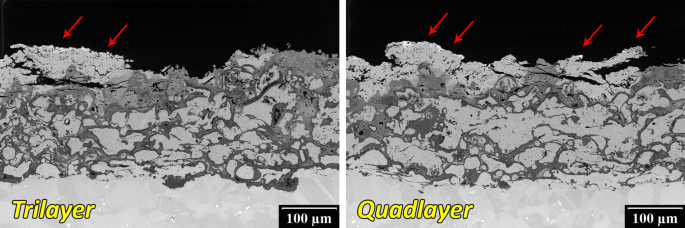
Coating failure at the bottom of the laser-rig crater. Arrows denote GZO residues on residues of TC1 YSZ
-
In the areas, where the top-coat has not yet delaminated, both coatings showed practically the same failure mode (Fig. 12 and 13). Major crack propagated above the bond-coat preferentially along or across the TGO and above the TC1 YSZ/TC2 GZO interface. When diverted due to the local bond-coat protrusions, crack propagated also through TC1 YSZ layer.
Fig. 12 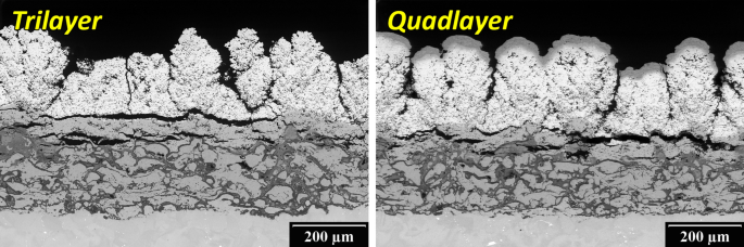
Cracking of the coating above the bond-coat in the areas adjacent to the laser-rig crater
Fig. 13 
Detail of interface failure between TC1 YSZ and TC2 GZO (left) and BC and TC1 YSZ (right). Arrows denote residual GZO on TC1 YSZ
-
The presence of TC3 YAG layer had no obvious influence on the coating failure mode.


Metallographic cross section plane intersected also one of the “dimples” (Fig. 10 and 14) revealing at its bottom presence of YSZ residues and various oxides originating from NiCrAlY bond-coat (see EDS map in Fig. 14). Shape of the “dimple” also confirmed previous observation from the free surfaces, i.e., that “dimples” were formed when individual GZO columns widening toward the free surface detached from the coating. Such gradually widening columns are often found above substrate/bond-coat asperities (see, e.g., Fig. 1). However, it took several hundreds of laser-rig cycles before “dimples” started to develop. Following mechanism of “dimple” formation was therefore proposed—oxides growing faster around the bond-coat asperities due to easier access of oxygen started to push the columns out from the coating. Pushing was alleviated by the shape of the columns widening toward the surface, which were not supported by interlocking with the surrounding columns. This created interfacial failure below the columns which mitigated heat removal from the top-coat and led to formation of hot-spots. Formation of such miniature hot-spots was indeed observed at the beginning of late laser-rig heating cycles and induced additional stresses and signalized imminent column detachment. After the column was detached, coating partially lost its protective function, which further promoted oxidation of material below the dimple due to elevated temperature and easier interaction with the surrounding environment.

Cross section of “dimple” from Fig. 10 (left) and detail of corresponding energy-dispersive spectroscopy EDS elemental map (right)
Mechanism suggested above may also explain why formation of “dimples” was not observed during the TCF test as it required increased test temperature, faster oxides growth, and higher heating/cooling rates.
Comparison of TCF and Laser-Rig Results
It needs to be pointed out that the Trilayer and Quadlayer TBC failure modes in TCF and laser-rig testing exhibited coincident features (compare Fig. 3 and 12). The mixed failure generally occurred at the (i) TGO/YSZ interface, (ii) YSZ/GZO interface, and (iii) within the YSZ interlayer; which developed concomitantly with the high oxidation of the bond-coat. In addition, in both individual tests, the two TBC architectures exhibited comparable lifetime (Fig. 2 and 5), i.e., no TBC ranked “better” than the other depending on the test.
In “simple terms,” it can be stated that TCF testing evaluates the ability of the TBC to resist (i) the stresses of the thermal cycle, as well as (ii) the stresses generated by the thickening of the TGO layer. On the other hand, it can be stated that thermal gradient cycle testing (e.g., laser-rig) evaluates the ability of the TBC to resist also the stresses developed by the temperature slope (ΔT) along the thickness of the TBC/substrate system (in addition to the other two previously stated). Moreover, the heating/cooling rates and dwell times of both thermal cycle tests tend to be significantly different. Consequently, the similarities observed in this work between TCF and laser-rig results are very interesting and are not very common. In spite of that, it is not the objective of this work to analyze in details why these similarities occurred. Nonetheless, it is worth to mention that other studies showing the comparison of TCF and thermal gradient cycle tests for TBC evaluation revealed different results.
For example, Vassen and Stover Ref 40 performed TCF and burner-rig testing in six distinct sets (i.e., microstructures) of APS YSZ TBCs, which were sprayed on the same type of puck-shaped bond-coated substrates. The TCF test was performed at 1100 °C with 24-hour-long cycles. The burner-rig cycle setup was the 5 min hot and 2 min cool type, just like the one employed in this work. The results showed an opposite trend in the performance ranking, in the sense that the TBCs that exhibited a “good” thermal cycle performance in TCF test tended to exhibit a “weaker” performance in burner-rig testing (and vice versa).
Helminiak et al. Ref 41 tested and compared the performance of three distinct sets of APS YSZ TBCs via TCF and thermal gradient cycle testing (jet engine thermal shock—JETS), which were also sprayed on the same type of puck-shaped bond-coated substrates. Here the results also showed an opposite trend in the performance ranking, but this time in the sense that the TBCs failed in distinct zones when tested in isothermal (TCF) or thermal gradient conditions.
Consequently, the lack of correlation in the results of both testing systems above cited (i.e., TCF versus thermal gradient test) was likely influenced by a group of factors acting independently or in group, some of which included (Ref 40, 41): (i) dissimilar substrate temperatures achieved in TCF and thermal gradient, (ii) non-uniform TBC and substrate temperature levels during thermal gradient, (iii) distinct ceramic TBC thicknesses, and (iv) mismatched TBC/substrate gradient temperature levels.
It is important to remember that in this current work, both ceramic multilayered top-coats exhibited similar total thickness values (~ 211-242 µm) and were sprayed over the same bond-coat. The temperatures of the substrates during cycling were comparable, i.e., 1100 °C for TCF and ~ 1074 °C for laser-rig cycling (Table 2). During laser-rig cycling, the surface temperatures of the Trilayer and Quadlayer TBCs were comparable at ~ 1544 and ~ 1526 °C, respectively (Table 2). Finally, the thermal gradient from the top coat to the substrate closely matched each other, being ~ 465 °C for the Trilayer and ~ 458 °C for the Quadlayer (Table 2). Consequently, it is hypothesized that these conditions influenced the similarities of the thermal cycle results reported in this manuscript.
Conclusions
-
Two types of multilayered TBCs were successfully deposited by high-enthalpy WSP-H plasma torch on Ni-based superalloys and tested in harsh conditions of thermal cycling fatigue (TCF) test and laser-rig (LR) test. “Trilayer” and “Quadlayer” coatings consisted of NiCrAlY bond-coat (sprayed from coarse dry powder), dense YSZ (sprayed from solution), columnar GZO (sprayed from suspension), and optional dense YAG overlayer (sprayed from suspension). Thermal cycling was based on repeated exposition of samples to periods of rapid heating, dwell at high temperature (TCF—60 min @ 1100 °C, LR—5 min @ ~ 1530 °C) and rapid cooling (TCF—10 min, LR—2 min). Both isothermal TCF test and gradient laser-rig test thus exposed coatings to demanding combination of (very) high temperature and thermal shocks which eventually led to coating failure accompanied with observable changes in the coatings microstructure, namely change of phase composition, sintering, and interdiffusion.
-
Coatings failure was observed after 800-850 TCF cycles (totaling thermal exposure to 800-850 h @ 1100 °C) and 863 + laser-rig cycles (totaling ~ 72 h @ ~ 1530 °C). No statistically significant differences were observed between both coatings. In other words, YAG deposition did not compromise thermal shock properties of the deposited coating.
-
TCF lifetime of TBC with GZO deposited by WSP-H technology directly on NiCrAlY bond-coat was in our previous study about 15% lower (Ref 15), which declares the benefit of deposition of dense YSZ interlayer. Moreover, no formation of new phases originating from potential high-temperature interaction between bond-coat/TGO and GZO (Ref 15, 42) was observed, which declares their successful separation by TC1 YSZ interlayer.
-
Despite different thermal regimes used in TCF and laser-rig test (namely maximum surface temperature, presence of thermal gradient, and heating/cooling rates during thermal shocks), both coatings exhibited in both tests similar failure. Bond-coat showed heavy internal oxidation, but coatings primarily failed due to horizontal cracking above the bond-coat, typically at TGO/YSZ or YSZ/GZO interfaces, or within YSZ interlayer. Merging of gradually forming cavities eventually led to top-coat spallation and large-scale delamination.
-
It is hypothesized that the similitudes observed in the performance ranking and failure of these TBCs via TCF and laser-rig were influenced by these following factors that occurred in this study: (i) comparable temperature levels of the coatings and substrates, (ii) similar thicknesses of the TBCs, and (iii) near the same TBC/substrate thermal gradients.
-
During the late laser-rig test, both TBCs developed several miniature hot-spots which preceded detachment of individual GZO columns, thus exposing underlying sublayers. It should be noted that in laser-rig test, TBC surface temperature (~ 1530 °C) was higher than melting point of NiCrAlY (~ 1400 °C). Nevertheless, no bond-coat melting was observed which confirms that both TBCs retained their thermal insulation function until the end of the test.
-
The results obtained from both thermal cycling fatigue (TCF) test and laser-rig test demonstrate that high-throughput WSP-H technology may provide interesting cost-effective alternative to conventional plasma torches for the deposition of novel TBCs for various industrial applications.
References
N.P. Padture, M. Gell, and E.H. Jordan, Thermal Barrier Coatings for Gas-Turbine Engine Applications, Science, 2002, 296(5566), p 280-284
J.L. Smialek and R.A. Miller, Revisiting the Birth of 7YSZ Thermal Barrier Coatings: Stephan Stecura, Coatings, 2018, 8(7), p 6
R. Darolia, Thermal Barrier Coatings Technology: Critical Review, Progress Update, Remaining Challenges and Prospects, Int. Mater. Rev., 2013, 58(6), p 315-348
R. Vassen, M.O. Jarligo, T. Steinke, D.E. Mack, and D. Stover, Overview on Advanced Thermal Barrier Coatings, Surf. Coatings Technol., 2010, 205, p 938-942
V. Viswanathan, G. Dwivedi, and S. Sampath, Engineered Multilayer Thermal Barrier Coatings for Enhanced Durability and Functional Performance, J. Am. Ceram. Soc., 2014, 97(9), p 2770-2778
E. Bakan and R. Vaßen, Ceramic Top Coats of Plasma-Sprayed Thermal Barrier Coatings: Materials, Processes, and Properties, J. Therm. Spray Technol., 2017, 26(6), p 992-1010
S. Mahade, D. Zhou, N. Curry, N. Markocsan, P. Nylen, and R. Vassen, Tailored Microstructures of Gadolinium Zirconate/YSZ Multi-Layered Thermal Barrier Coatings Produced by Suspension Plasma Spray: Durability and Erosion Testing, J. Mater. Process. Technol., 2019, 264, p 283-294
S. Mahade, R. Li, N. Curry, S. Bjorklund, N. Markocsan, and P. Nylen, Isothermal Oxidation Behavior of Gd2Zr2O7/YSZ Multilayered Thermal Barrier Coatings, Int. J. Appl. Ceram. Technol., 2016, 13(3), p 443-450
M.P. Schmitt, J.M. Schreiber, A.K. Rai, T.J. Eden, and D.E. Wolfe, Development and Optimization of Tailored Composite TBC Design Architectures for Improved Erosion Durability, J. Therm. Spray Technol., 2017, 26(6), p 1062-1075
A. Feuerstein, J. Knapp, T. Taylor, A. Ashary, A. Bolcavage, and N. Hitchman, Technical and Economical Aspects of Current Thermal Barrier Coating Systems for Gas Turbine Engines by Thermal Spray and EBPVD: A Review, J. Therm. Spray Technol., 2008, 17(2), p 199-213
A. Tricoire, B. Kjellman, J. Wigren, M. Vanvolsem, and L. Aixala, Insulated Piston Heads for Diesel Engines, J. Therm. Spray Technol., 2009, 18(2), p 217-222
R. Musalek, J. Medricky, T. Tesar, J. Kotlan, Z. Pala, F. Lukac, T. Chraska, and N. Curry, Suspensions Plasma Spraying of Ceramics with Hybrid Water-Stabilized Plasma Technology, J. Therm. Spray Technol., 2017, 26(1–2), p 37-46
R. Musalek, J. Medricky, T. Tesar, J. Kotlan, Z. Pala, F. Lukac, K. Illkova, M. Hlina, T. Chraska, P. Sokolowski, and N. Curry, Controlling Microstructure of Yttria-Stabilized Zirconia Prepared from Suspensions and Solutions by Plasma Spraying with High Feed Rates, J. Therm. Spray Technol., 2017, 26(8), p 1787-1803
J. Medricky, R. Musalek, M. Janata, T. Chraska, and F. Lukac, Cost-Effective Plasma Spraying for Large-Scale Applications, in ITSC 2018: International Thermal Spray Conference and Exposition—2018 Conference Proceedings, F. Azarmi, K. Balani, T. Eden, T. Hussain, Y.C. Lau, H. Li, K. Shinoda, F.-L. Toma and J. Veilleux, Ed. May 7–10, 2018 (Orlando, FL, USA), ASM International, 2018, p 683-689
R. Musalek, T. Tesar, J. Medricky, F. Lukac, T. Chraska, and M. Gupta, Microstructures and Thermal Cycling Properties of Thermal Barrier Coatings Deposited by Hybrid Water-Stabilized Plasma Torch, J. Therm. Spray Technol., 2020, 29(3), p 444-461
M. Gupta, R. Musalek, and T. Tesar, Microstructure and Failure Analysis of Suspension Plasma Sprayed Thermal Barrier Coatings, Surf. Coatings Technol., 2020, 382, p 125218
G. Dwivedi, V. Viswanathan, S. Sampath, A. Shyam, and E. Lara-Curzio, Fracture Toughness of Plasma-Sprayed Thermal Barrier Ceramics: Influence of Processing, Microstructure, and Thermal Aging, J. Am. Ceram. Soc., 2014, 97(9), p 2736-2744
S. Mahade, N. Curry, S. Bjorklund, N. Markocsan, and P. Nylen, Failure Analysis of Gd2Zr2O7/YSZ Multi-Layered Thermal Barrier Coatings Subjected to Thermal Cyclic Fatigue, J. Alloys Compd., 2016, 689, p 1011-1019
P. Carpio, M.D. Salvador, A. Borrell, and E. Sanchez, Thermal Behaviour of Multilayer and Functionally-Graded YSZ/Gd2Zr2O7 Coatings, Ceram. Int., 2017, 43(5), p 4048-4054
M. Gell, J. Wang, R. Kumar, J. Roth, C. Jiang, and E.H. Jordan, Higher Temperature Thermal Barrier Coatings with the Combined Use of Yttrium Aluminum Garnet and the Solution Precursor Plasma Spray Process, J. Therm. Spray Technol., 2018, 27(4), p 543-555
R. Kromer, F. Mauget, L. Despres, S. Costil, and J. Cormier, Thermo-Mechanical Fatigue Evaluation of a Thermal Barrier Coating Bond-Coatless System, Mater. Sci. Eng., A, 2019, 756, p 130-141
K.G. Schmitt-Thomas, H. Haindl, and D. Fu, Modifications of Thermal Barrier Coatings (TBCs), Surf. Coatings Technol., 1997, 94–95, p 149-154
J.-H. Lee, P.-C. Tsai, and C.-L. Chang, Microstructure and Thermal Cyclic Performance of Laser-Glazed Plasma-Sprayed Ceria-Yttria-Stabilized Zirconia Thermal Barrier Coatings, Surf. Coatings Technol., 2008, 202(22–23), p 5607-5612
G. Antou, G. Montavon, F. Hlawka, A. Cornet, C. Coddet, and F. Machi, Modification of Ceramic Thermal Spray Deposit Microstructures Implementing in Situ Laser Remelting, Surf. Coatings Technol., 2003, 172(2–3), p 279-290
L. Pawlowski, Thick Laser Coatings: A Review, J. Therm. Spray Technol., 1999, 8(2), p 279-295
U. Savitha, V. Srinivas, G. Jagan Reddy, A.A. Gokhale, and M. Sundararaman, Additive Laser Deposition of YSZ on Ni Base Superalloy for Thermal Barrier Application, Surf. Coatings Technol., 2018, 354, p 257-267
F. Cernuschi, P. Bison, and J.G. Sun, Thermal Diffusivity of TBC: Results of a Small Round Robin Test and Considerations about the Effect of the Surface Preparation and the Measuring Approach, Surf. Coatings Technol., 2014, 258, p 284-292
W. Chi, S. Sampath, and H. Wang, Comparison of the Thermal Transport Property Measurements of Thermally Sprayed Coatings by the Laser and Xenon Flash Techniques, J. Therm. Spray Technol., 2007, 16(3), p 444-448
V. Maurel, V. Guipont, M. Theveneau, B. Marchand, and F. Coudon, Thermal Cycling Damage Monitoring of Thermal Barrier Coating Assisted with LASAT (LAser Shock Adhesion Test), Surf. Coatings Technol., 2019, 380, p 125048
V. Guipont, G. Bégué, G. Fabre, and V. Maurel, Buckling and Interface Strength Analyses of Thermal Barrier Coatings Combining Laser Shock Adhesion Test to Thermal Cycling, Surf. Coatings Technol., 2019, 378, p 124938
R.W. Jackson, E.M. Zaleski, B.T. Hazel, M.R. Begley, and C.G. Levi, Response of Molten Silicate Infiltrated Gd2Zr2O7 Thermal Barrier Coatings to Temperature Gradients, Acta Mater., 2017, 132, p 538-549
R.S. Lima, B.R. Marple, and P. Marcoux, Thermal Gradient Behavior of TBCs Subjected to a Laser Gradient Test Rig: Simulating an Air-to-Air Combat Flight, J. Therm. Spray Technol., 2016, 25(1), p 282-290
R.S. Lima and B.R. Marple, Insights on the High-Temperature Operational Limits of ZrO2-Y2O3 TBCs Manufactured via Air Plasma Spray, J. Mater. Eng. Perform., 2017, 26(3), p 1272-1282
T. Fiedler, J. Rosler, and M. Baker, A New Metallic Thermal Barrier Coating System for Rocket Engines: Failure Mechanisms and Design Guidelines, J. Therm. Spray Technol., 2019, 28(7), p 1402-1419
Y. Wu, P.-F. Hsu, Y. Wang, M.H. McCay, D.E. Croy, D. Moreno, L. He, C. Wang, and H. Zhang, Laser Thermal Gradient Testing and Fracture Mechanics Study of a Thermal Barrier Coating, J. Therm. Spray Technol., 2019, 28(6), p 1239-1251
J. Schloesser, M. Baker, and J. Rosler, Laser Cycling and Thermal Cycling Exposure of Thermal Barrier Coatings on Copper Substrates, Surf. Coatings Technol., 2011, 206(7), p 1605-1608
M.H. McCay, P.-F. Hsu, D.E. Croy, D. Moreno, and M. Zhang, The Fabrication, High Heat Flux Testing, and Failure Analysis of Thermal Barrier Coatings for Power Generation Gas Turbines. in ASME Turbo Expo 2017 Turbomachinery Technical Conference and Exposition, June 26–30, 2017 (Charlotte, NC, USA), American Society of Mechanical Engineers (ASME), 2017, p. 9
M. Gupta, N. Curry, P. Nylén, N. Markocsan, and R. Vaßen, Design of next Generation Thermal Barrier Coatings—Experiments and Modelling, Surf. Coatings Technol., 2013, 220, p 20-26
A.C. Karaoglanli, K.M. Doleker, and Y. Ozgurluk, Interface Failure Behavior of Yttria Stabilized Zirconia (YSZ), La2Zr2O7, Gd2Zr2O7, YSZ/La2Zr2O7 and YSZ/Gd2Zr2O7 Thermal Barrier Coatings (TBCs) in Thermal Cyclic Exposure, Mater. Charact., 2020, 159, p 110072
R. Vassen and D. Stover, Influence of Microstructure on the Thermal Cycling Performance of Thermal Barrier Coatings, Thermal Spray: Global Coating Solutions, B.R. Marple, M.M. Hyland, Y.-C. Lau, C.-J. Li, R.S. Lima, and G. Montavon, Ed., Springer, Beijing, 2007, p 417-422
M.A. Helminiak, N.M. Yanar, F.S. Pettit, T.A. Taylor, and G.H. Meier, Factors Affecting the Microstructural Stability and Durability of Thermal Barrier Coatings Fabricated by Air Plasma Spraying, Mater. Corros., 2012, 63(10), p 929-939
R.M. Leckie, S. Krämer, M. Ruhle, and C.G. Levi, Thermochemical Compatibility between Alumina and ZrO2-GdO3/2 Thermal Barrier Coatings, Acta Mater., 2005, 53, p 3281-3292
Acknowledgments
Financial support through project 19-10246S “Deposition mechanism and properties of multiphase plasma sprayed coatings prepared with liquid feedstocks’’ funded by Czech Science Foundation is gratefully acknowledged. Help of Jean-Claude Tremblay with execution of laser-rig test is highly appreciated.
Author information
Authors and Affiliations
Corresponding author
Additional information
Publisher's Note
Springer Nature remains neutral with regard to jurisdictional claims in published maps and institutional affiliations.
Production Notes: Credit Line: This article is an invited paper selected from abstracts submitted for the 2020 International Thermal Spray Conference, ITSC2020, that was to be held from June 10-12, 2020, in Vienna, Austria. The conference was cancelled due to the coronavirus (COVID-19) pandemic. The paper has been expanded from the planned presentation.
Rights and permissions
About this article

Cite this article
Musalek, R., Tesar, T., Medricky, J. et al. High-Temperature Cycling of Plasma Sprayed Multilayered NiCrAlY/YSZ/GZO/YAG Thermal Barrier Coatings Prepared from Liquid Feedstocks. J Therm Spray Tech 30, 81–96 (2021). https://doi.org/10.1007/s11666-020-01107-5
Received:
Revised:
Accepted:
Published:
Issue Date:
DOI: https://doi.org/10.1007/s11666-020-01107-5