


Abstract
The estimation of integral wall force using solely magnetic measurement in RFX-mod experiment is presented. The vertical and sideways forces are directly obtained from the magnetic field measured outside the vacuum vessel. Several theoretical predictions related to tokamak are also verified for the reversed field pinch configuration. The contribution of different modes to the force is also considered and analyzed. This method of calculation would be relevant for future nuclear fusion reactors where magnetic measurements will be located only outside the vacuum vessel.
Export citation and abstract BibTeX RIS

Original content from this work may be used under the terms of the Creative Commons Attribution 4.0 license. Any further distribution of this work must maintain attribution to the author(s) and the title of the work, journal citation and DOI.
1. Introduction
Magnetic confinement fusion devices are characterized by pulsed operations in which large currents are induced in the vacuum vessel (wall) leading to electromagnetic forces that may be critical for the structural integrity of the machine. In tokamaks, the wall force due to disruptions may lead to a global horizontal displacement of the whole torus as reported in JET experiment [1]. Such wall force is called sideways force and it is related to asymmetric magnetic perturbations due to the symmetry-breaking plasma deformations [1–20] or wall non-uniformity along the toroidal direction (asymmetric wall) [21, 22]. In a Cartesian system of coordinates—where the z axis corresponds to the torus axis—sideways force corresponds to Fx and Fy components of the integral wall force while the remaining Fz component is the vertical force.
In the past, sideways and vertical forces were investigated usually starting from numerical simulations whose assumptions were not always explicitly clear. This inevitably led to a large variability in the resulting wall force for the same plasma scenario spanning several orders of magnitudes [1–20, 23, 24]. More recently, the investigation of such assumptions behind numerical simulations led to a theory of wall forces which is only based upon Maxwell's equations [14, 25]. In particular, it was discovered [14, 25] and numerically verified [17, 26, 27] that the wall resistivity, the penetration of the magnetic perturbation through the wall, the poloidal current induced in the wall, the kink-mode coupling, the plasma position in the vacuum vessel must be the elements essentially affecting the disruption forces.
In this paper, the estimation of the integral wall force on the vacuum vessel of the RFX-mod experiment is presented using solely magnetic measurements. This approach relies on the upon mentioned theory in which the wall force can be directly obtained from the magnetic field measured on a surface enclosing the wall (i.e. vacuum vessel). RFX-mod ( m, a = 0.5 m) [28, 29] is equipped with many magnetic sensors on the external surface of the vessel allowing to measure all the necessary magnetic field components. The proposed method of calculation would be relevant for future nuclear fusion reactors where magnetic measurements will be located only outside the vacuum vessel. Differently from mechanical sensors, the proposed method is characterized by a high temporal resolution (i.e. the sampling rate of magnetic sensors) and low computational requirements. In addition, it allows to evaluate the wall force during all the plasma discharge without any limitation related to plasma dynamics.
The paper is organized as follows: section 2 describes the mathematical model describing the wall forces; in section 3, the methodology for the evaluation of wall forces from magnetic measurements in RFX-mod experiment is described; section 4 reports the results of the calculation; finally, section 5 draws the conclusions.
2. Mathematical formulation
The mathematical model for the calculation of the integral force on a toroidal conducting wall surrounding a toroidal plasma is fully described in [25]. The relations adopted in this paper are here reported for clarity of reading. The integral wall force  along a generic direction c can be expressed as:
where  is the integral force on plasma, µ0 is the vacuum magnetic permeability, B is the magnetic field (i.e. magnetic flux density), c is any constant vector,
  denotes any toroidal surface enclosing the wall in the outer vacuum so that the external conductors remain outside, and
  is the outwardly oriented area element of
  . In the following it is assumed
  which is a perfectly suitable approximation in (1) if we expect large
  [13–15, 17, 21].
The force on the wall is given by the surface integral in (1) entirely determined by B on the 2D toroidal surface  enclosing the wall; this has been chosen in order to allow the evaluation of (1) by the data from external magnetic measurements. This can be done because the regions with no plasma current density outside the wall can be included into the integral in (1) without affecting the result. The measured magnetic field B on
  can be expressed as
  , where
  is the axisymmetric part of B while b is the remainder oscillating component over the toroidal angle (i.e. the kink-like perturbation). Thus, the force on the wall can be expressed as:

with contributions depending on  and b:
Two integral forces on the wall are of practical interest: vertical Fz
and sideways (horizontal or lateral)  . These can be evaluated using (1) by properly choosing the unit constant vector c, particularly
  for the vertical force and
  (or
(or  ) for the sideways one.
3. Experimental estimation of wall forces
RFX-mod is equipped with magnetic sensors located externally to the vacuum vessel (r = 0.508 m) allowing to measure all the magnetic field components (figure 1). In particular, there are  radial saddle loops poloidally located at
  and toroidally distributed every 7.5∘ from 0∘ to 360∘ and
  biaxial pick-up coils poloidally located at
  and toroidally distributed every 7.5∘ from 0∘ to 360∘. In order to evaluate the integral (1), the measured magnetic fields on each sensor location (colored markers in figure 2) are interpolated on a structured triangular mesh of the 2D toroidal surface
  (figure 2). This is an axisymmetric toroidal surface with circular cross section (r = 0.508 m) where the sensors are located (figure 2). Then, the surface integral in (1) is numerically evaluated using Gaussian quadrature. In this way, the sideways (
 ) and vertical force (Fz
) acting on RFX-mod vacuum vessel (i.e. wall) can be estimated solely from magnetic measurements during all the phases of the discharge.
) and vertical force (Fz
) acting on RFX-mod vacuum vessel (i.e. wall) can be estimated solely from magnetic measurements during all the phases of the discharge.

Figure 1. Vacuum vessel, Passive Stabilizing Shell (PSS) and ex-vessel magnetics: saddle loops centered at  and pick-up coils at
  .
.
Download figure:
Standard image High-resolution image
Figure 2. Magnetic sensors location on the 2D toroidal surface  , triangular mesh of
  (azure) and unit normal vectors (red arrows) for the force evaluation.
Download figure:
Standard image High-resolution imageIn addition, each force contribution in (2) can be evaluated by properly defining both the axisymmetric component ( ) and the perturbation (b) of the measured magnetic field (B):

A Fourier decomposition of each measured magnetic field component is performed by Fast Fourier Transform (FFT) where the coefficients of the 2D discrete Fourier transformation are:
where  denotes the direction of measurement (radial, poloidal and toroidal, respectively),
  is the measured magnetic field component constituted by M × N samples, θj
and φk
are the poloidal and toroidal angles where sensors are located, respectively. As previously reported, for RFX-mod the number of magnetic field samples in poloidal and toroidal direction are M = 4 and N = 48, respectively. Being
is the measured magnetic field component constituted by M × N samples, θj
and φk
are the poloidal and toroidal angles where sensors are located, respectively. As previously reported, for RFX-mod the number of magnetic field samples in poloidal and toroidal direction are M = 4 and N = 48, respectively. Being  a real signal, the DFT provides each harmonic component and its complex conjugate. Thus, the
  part is properly defined by selecting
  components (i.e. axisymmetric) and applying the inverse FFT (iFFT):
Then, by subtracting the axisymmetric component  to the measured magnetic field B in (6), the perturbation b is defined. According to the above-mentioned properties of the DFT of real signals, the separation of single harmonic component is accomplished by removing the corresponding term and the associated complex conjugate one from the full spectrum. This procedure is performed for all the measured magnetic field components (i.e. radial, poloidal, toroidal) at all time instants providing their axisymmetric and perturbative parts (figure 3). Finally, such fields are interpolated on the 2D mesh of
  and the surface integrals in (3)–(5) are numerically evaluated.

Figure 3. Time evolution of RFX-mod shot no. 29283 measured magnetic field on  (red) in radial (left), toroidal (center) and poloidal (right) directions; the axisymmetric part and perturbation are represented in black and blue, respectively.
Download figure:
Standard image High-resolution imageThe FFT decomposition in (7) can also be used as a 'harmonic filter' on the measured magnetic field while the iFFT in (8) provides the filtered magnetic field with the 'desired' harmonic content. In this way, the contributions of different (m, n) modes to the wall force ( ) can be evaluated by solving (1) with the filtered magnetic field. In the following, the force computed using the experimental magnetic field (figure 4) will be denoted as experimental and chosen as reference. In other words, this corresponds to the force computed using the full spectrum of B corresponding to
  and
and  .
.

Figure 4. Time evolution of plasma current and estimated sideways and vertical forces for the RFX-mod shot no. 29283.
Download figure:
Standard image High-resolution image4. Results
In the following, the sideways and vertical forces of an RFX-mod experimental plasma discharge are evaluated. The selected high-current RFP plasma shot (#29283) includes all the possible phases of a discharge (figure 4): the ramp-up and flat-top phases, which are controlled by the experimenter, and the unpredicted fast termination phenomenon. This is a fast uncontrolled transient event that leads to an abrupt termination of the discharge; such phenomenon occurs, with some phenomenological differences, in both tokamak and RFP magnetic configurations.
The estimated sideways and vertical forces are evaluated for all the discharge phases as shown in figure 4: all the forces exhibit an oscillation in time with a maximum value of about  related to the vertical force (Fz
). At the beginning of the discharge, the force acts mainly in the vertical direction while Fx
and Fy
components are almost zero. Then, both Fx
and Fy
increase in magnitude approximately starting from
related to the vertical force (Fz
). At the beginning of the discharge, the force acts mainly in the vertical direction while Fx
and Fy
components are almost zero. Then, both Fx
and Fy
increase in magnitude approximately starting from  . The sideways force is due to both Fx
and Fy
whose amplitudes are about a half of Fz
in the beginning of the discharge but after 50 ms they are of the same order of magnitude. The Fy
force has similar amplitude of Fx
but with opposite sign and a less marked oscillating behavior in time. As it will be described in section 4.3, the difference in Fx
and Fy
could be related to the presence of the Passive Stabilizing Shell (PSS) which is a 3 mm copper toroidal structure clamped on the external surface of the vacuum vessel (figure 1). The PSS is electrically isolated from the vessel and characterized by a toroidal cut (i.e. poloidal plane cut) located at
. The sideways force is due to both Fx
and Fy
whose amplitudes are about a half of Fz
in the beginning of the discharge but after 50 ms they are of the same order of magnitude. The Fy
force has similar amplitude of Fx
but with opposite sign and a less marked oscillating behavior in time. As it will be described in section 4.3, the difference in Fx
and Fy
could be related to the presence of the Passive Stabilizing Shell (PSS) which is a 3 mm copper toroidal structure clamped on the external surface of the vacuum vessel (figure 1). The PSS is electrically isolated from the vessel and characterized by a toroidal cut (i.e. poloidal plane cut) located at  that prevents the circulation of a net toroidal current (figure 5).

Figure 5. Top view of the shell with a toroidal cut at  .
.
Download figure:
Standard image High-resolution imageIt is worth noting the case without a fast termination shown in figure 6 (#29282): the amplitude of each force component gradually decreases as the plasma current slowly ramps down in a controlled way. Considering the case with fast termination (#29283, figure 4), a quick fall of the force amplitude occurs as the current abruptly goes to zero. As it will be shown in section 4.3, the sideways force generation requires the existence of a  magnetic perturbation outside the wall. Differently from tokamaks—in which disruptions are related to the n = 1 kink perturbations responsible for the sideways force [13]—the n = 1 toroidal perturbation in RFP is already present from the very beginning of the discharge and it is not significantly affected in amplitude during fast termination (figure 7). In fact, fast termination is usually related to an increased energy in the magnetic field of dynamo modes and to a broadening of their spectrum towards the higher n [30].

Figure 6. Time evolution of plasma current and estimated sideways and vertical forces for the RFX-mod shot no. 29282 where no fast termination occurs.
Download figure:
Standard image High-resolution image
Figure 7. Comparison of the amplitude of  mode for the case with fast termination (red, #29283) and without fast termination (blue, #29282): no significantly change is revealed for the two cases.
Download figure:
Standard image High-resolution image4.1. General properties of the wall forces in RFP plasmas with respect to tokamaks
The three contributions (3)–(5) are evaluated for each component of the wall force (i.e. Fx
, Fy
, Fz
) of the previously analyzed RFP plasma discharge. Differently from tokamak, in RFP configuration the magnitude of Fx
is comparable and sometimes even larger than Fz
(figure 4) since the perturbation b is not negligible with respect to  for both radial and toroidal components (figure 3). Conversely, tokamak plasmas cannot produce a magnetic perturbation b comparable to the axisymmetric component
  which leads to
  and therefore larger vertical forces with respect to sideways ones [25].
Considering the sideways force ( ), both are determined mainly by the FBb
component (figures 8(a) and (b)); thus, the presence of perturbations with φ dependence outside the wall is necessary for the existence of sideways force. The condition
), both are determined mainly by the FBb
component (figures 8(a) and (b)); thus, the presence of perturbations with φ dependence outside the wall is necessary for the existence of sideways force. The condition  [25] is verified: an axisymmetric field
  cannot produce alone an asymmetric force Fx
or Fy
as stated in (3). The Fbb
contribution is negligible for both Fx
and Fy
. Regarding the vertical force Fz
, the main contribution is due to the axisymmetric component FBB
(figure 8(c)) which is particularly large in the first stages of the discharge. Moreover, the condition
cannot produce alone an asymmetric force Fx
or Fy
as stated in (3). The Fbb
contribution is negligible for both Fx
and Fy
. Regarding the vertical force Fz
, the main contribution is due to the axisymmetric component FBB
(figure 8(c)) which is particularly large in the first stages of the discharge. Moreover, the condition  [25] is also verified.

Figure 8. Different contributions  to the sideways (8(a) and (b)) and vertical (8(c)) forces of RFX-mod shot no. 29283.
Download figure:
Standard image High-resolution imageContrarily to tokamaks, in RFP plasmas  : the magnitude of
  is comparable and sometimes higher than
  . This is related to the fact that a RFP plasma produces a magnetic perturbation b comparable to the axisymmetric component
  for both radial and toroidal components (figure 3).
4.2. Harmonic analysis on the vertical wall force
As reported in section 4.1, the vertical force Fz
is mainly due to FBB
. In terms of harmonics, this corresponds to the force due to the n = 0 component of the magnetic field (i.e. the axisymmetric field). The contribution of different poloidal harmonics on  is here analyzed by considering different
  modes. A shown in figure 9, the
  leads to a Fz
similar to the experimental one but with a remarkable difference in amplitude, particularly after 50 ms; the
leads to a Fz
similar to the experimental one but with a remarkable difference in amplitude, particularly after 50 ms; the  mode leads to a stationary value of force of about
  . By considering both
  and
and  mode, the related vertical force perfectly fits the experimental one in both magnitude and time evolution (figure 9). Therefore, the toroidal coupling of modes with same n = 0 toroidal number but different poloidal number m is crucial in determining the vertical force.

Figure 9. Different (m, n) mode contributions to the vertical force Fz
: the contributions of  and
and  is crucial to properly estimate Fz
.
is crucial to properly estimate Fz
.
Download figure:
Standard image High-resolution imageThese results confirm that the vertical force on the wall is produced by the n = 0 part of the magnetic field [25] and no vertical force is related to n = 1 component; this is consistent with the previous considerations of  and
and  . Moreover, it is shown that the coupling of n = 0 modes with different poloidal mode number m—specifically the
  —is fundamental for the correct dynamics and magnitude of the vertical force.
4.3. Harmonic analysis on the sideways wall force
Regarding the sideways force, both Fx
and Fy
are mainly due to FBb
which requires both an axisymmetric (n = 0) and an oscillating (n = 1) component to exist [25]. The  mode leads to approximately the same value of Fx
(figure 10(a)) and Fy
(figure 10(b)) of the experimental case. Similar results are found for the
mode leads to approximately the same value of Fx
(figure 10(a)) and Fy
(figure 10(b)) of the experimental case. Similar results are found for the  mode. The
  and
and  modes coupled together lead to a better agreement with the experimental reference as shown in figure 11 in terms of absolute error (i.e
  ). The impact of the
  mode is relatively small for both Fx
and Fy
as it slightly improves the agreement with respect to the experimental case (figure 11).
mode is relatively small for both Fx
and Fy
as it slightly improves the agreement with respect to the experimental case (figure 11).
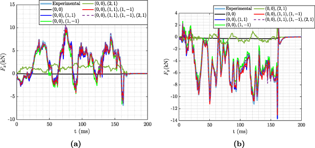
Figure 10. Different (m, n) mode contributions to the Fx (a) and Fy (b).
Download figure:
Standard image High-resolution image
Figure 11. Absolute error (i.e.  ) between the computed sideways force and the experimental one considering different modes.
Download figure:
Standard image High-resolution imageIt has also to be noted that the sideways force phase (i.e.  ) oscillates from 0∘ to
  : such oscillating behavior is well correlated with the phase of the
  mode (figure 12). The average value of the sideway force phase is about
  . The same phenomenology and average value have been observed in similar RFP plasma discharges. Such behavior could be related to the presence of the PSS whose toroidal cut at
  is the principle source of toroidal asymmetry. In fact, it is worth nothing that the average value of the sideways force phase (i.e.
  ) corresponds to the diametrically opposite location of the shell toroidal cut (
 ).
).

Figure 12. Sideways force phase (i.e.  ) (blue) and
  mode phase (red) time evolution.
Download figure:
Standard image High-resolution image
5. Conclusions
In this paper, the estimation of vertical and sideways forces solely from magnetic measurements is presented. The results are obtained in RFX-mod experiment but the method can be applied to any device whose diagnostic system allows to measure all the magnetic field components on the external surface of the vacuum vessel. The wall force is evaluated for a 2 MA RFP plasma discharge in all its phases including a fast termination event.
Several theoretical predictions related to tokamak are also verified for RFP plasma: the vertical force is due to the axisymmetric component of the field; the sideways force is related to the existence of a perturbation interacting with  . Contrary to tokamaks, in RFP configuration the magnitude of the sideways force is comparable with the vertical one because of the comparable perturbation with respect to the axisymmetric component. The vertical force Fz
is due to the n = 0 component of the magnetic field (i.e. the axisymmetric field). Moreover, the toroidal coupling of modes with different poloidal numbers and same n = 0 toroidal number is crucial for the amplitude of Fz
. Considering sideways force, these requires both an axisymmetric (n = 0) and an oscillating (n = 1) component to exist. In particular, the
. Contrary to tokamaks, in RFP configuration the magnitude of the sideways force is comparable with the vertical one because of the comparable perturbation with respect to the axisymmetric component. The vertical force Fz
is due to the n = 0 component of the magnetic field (i.e. the axisymmetric field). Moreover, the toroidal coupling of modes with different poloidal numbers and same n = 0 toroidal number is crucial for the amplitude of Fz
. Considering sideways force, these requires both an axisymmetric (n = 0) and an oscillating (n = 1) component to exist. In particular, the  mode leads to sideways force (Fx
, Fy
) in well agreement with the one obtained with the measured magnetic field. Thus, suppressing the n = 1 component behind the wall would be sufficient for reducing the sideways force. In the same way, the suppression of m ≠ 0 outside the wall would reduce the vertical force.
mode leads to sideways force (Fx
, Fy
) in well agreement with the one obtained with the measured magnetic field. Thus, suppressing the n = 1 component behind the wall would be sufficient for reducing the sideways force. In the same way, the suppression of m ≠ 0 outside the wall would reduce the vertical force.
The proposed method of calculation could be relevant for future nuclear fusion reactors that would rely only upon ex-vessel magnetic sensors that are well shielded from the irradiation effects by the thick vacuum vessel. Moreover, it is characterized by a high temporal resolution—determined by the sampling rate of magnetic sensors- and low computational requirements that could potentially lead to a real-time application.
Acknowledgments
The authors are grateful to P. Zanca and A. Iaiunese for fruitful discussions and to M. Bernardi for preparing figures 1 and 5. This work has been carried out within the framework of the EUROfusion Consortium, funded by the European Union via the Euratom Research and Training Programme (Grant Agreement No. 101052200 - EUROfusion). Views and opinions expressed are however those of the author(s) only and do not necessarily reflect those of the European Union or the European Commission. Neither the European Union nor the European Commission can be held responsible for them.