Advanced Structural Materials for Gas-Cooled Fast Reactors—A Review
by
 , , ,
, , ,
Jakub Čížek
1 ,
,
Jana Kalivodová
2,
Miloš Janeček
3,*,
Josef Stráský
3,
Ondřej Srba
2 and
Anna Macková
4,5 1
Department of Low Temperature Physics, Charles University, V Holešovičkách 2, Prague 8, CZ-180 00 Prague, Czech Republic
2
Centrum Výzkumu Řež s.r.o., Hlavní 130, 250 68 Husinec-Řež, Czech Republic
3
Department of Physics of Materials, Charles University, Ke Karlovu 5, CZ-121 16 Prague, Czech Republic
4
Nuclear Physics Institute of the Czech Academy of Sciences, v. v. i., 250 68 Řež, Czech Republic
5
Department of Physics, Faculty of Science, J.E. Purkinje University, České Mládeže 8, 400 96 Ústi nad Labem, Czech Republic
*
Author to whom correspondence should be addressed.
Metals 2021, 11(1), 76; https://doi.org/10.3390/met11010076
Submission received: 19 November 2020
/
Revised: 24 December 2020
/
Accepted: 29 December 2020
/
Published: 1 January 2021
Abstract
:This review summarizes the development of the Gas-Cooled Fast Reactor (GFR) concept from the early 1970s until now, focusing specifically on structural materials and advanced fuel cladding materials. Materials for future nuclear energy systems must operate under more extreme conditions than those in the current Gen II or Gen III systems. These conditions include higher temperatures, a higher displacement per atom, and more corrosive environments. This paper reviews previous GFR concepts in light of several promising candidate materials for the GFR system. It also reviews the recent development of nuclear power and its use in the peaceful exploration of space. The final section focuses on the development and testing of new advanced materials such as SiCf/SiC composites and high entropy alloys (HEA) for the construction and development of GFRs.
1. Introduction
Only a combined strategy of employing all major sustainable clean energy options, including renewables, nuclear, efficiency, and conservation, can prevent the negative effects of climatic changes by the end of this century. Nuclear energy is the second largest source of low-carbon power [1] in the world, covering 10% of the global electricity consumption in 2017. Nuclear power is a part of the energy mix in 14 of the 28 European Union (EU) member states, representing 25% of the electricity produced in the EU (2017) [2].
Less than half of the world’s total energy consumption is currently used for electricity generation. The rest is heat consumption of residential, industrial, and transportation sectors. The highest share of heat was produced from natural gas and manufactured gases (39.2%), which was followed by renewable energies (26.5%) and solid fossil fuels (23.2%) [2]. Even though it is not yet a deeply explored issue in the EU, the heat generated by nuclear power plants could also be used for several applications, such as cooling, heating, process heat, desalination, hydrogen production, and the oil sand/oil shale extraction in Canada. There are many more applications [3] for heat utilization, e.g., iron and steel manufacturing at T > 1000 °C, chemical and pharmaceutical industry T~500–1000 °C, coke and refined petroleum products T~300–750 °C, and glass, cement, and ceramics at T > 1000 °C. Advanced nuclear cogeneration options may be different depending on the technology, reactor type, fuel type, and temperature level. An overview of nuclear systems and their defined operating temperature ranges, including the six advanced reactors agreed by the Generation IV International Forum, is shown in Table 1.
Table 1 shows that the GFR system can be advisable for covering the heat demand in a wide temperature range and, therefore, also in many non-electric applications (heating/cooling, desalination, process heat generation, chemical industry, refinery, and hydrogen production). In general, fast reactor systems have effective capability to breed fissile fuel and to transmute nuclear waste and eventually to realize the ultimate utilization of nuclear fission energy. In addition, energy conversion at high thermal efficiency is possible with the current design being considered, thus, increasing the economic benefit of GFRs.
However, there are several research and development challenges for GFRs including the ability to use a passive decay heat removal (DHR) system during accidental conditions, fuel cycle processes, and the compatibility of fuel and in-core structural materials/components with extreme conditions (high temperature, high pressure, and fast neutron radiation). This paper is focused on material research related to GFR development from 1970 up to the present.
The history of GFRs dates back to the 1960s, which was the dawn of the nuclear era. Both in the USA and in Europe, helium-cooled fast breeder projects were reported [4]. A concise overview of past GFRs is provided by van Rooijen [5]. It includes the Gas Breeder Memorandum (Germany), the USA program on GFR by Gulf General Atomic, The Gas Breeder Reactor Association (Europe), the UK program and the Japan fast reactor program. An overview of past GFR concepts and the proposed structural and fuel materials is shown in Table 2. The history of the development of GFRs in USA and Europe is described elsewhere [6]. The following chapter summarizes significant achievements since the 1970s, including the potential use of GFR for the space program.
2. Gas-Cooled Fast Reactor and ALLEGRO
2.1. The US GFR and Space Program
The first two important gas-cooled reactors have been developed in the United States by Gulf General Atomic in the 1970s. They consisted of the steam-raising and direct cycle versions of the high temperature gas-cooled reactor (HTGR) for electric power generation, hydrogen production, and chemical process applications, and the gas-cooled fast reactor (GFR), which was a high gain breeder.
In 2008, GA (USA) launched a GFR program, called the Energy Multiplier Module (EM2). The EM2 is a compact 265 MWe GFR with low-enriched uranium carbide fuels, which satisfies the physics design requirements of an ultra-long fuel cycle, high burnup, and compact reactor size, and is also economically competitive for large-scale commercial nuclear plants. It employs the silicon carbide composite (SiC/SiC) as both cladding and core structural material. The experimental verification of fuel and structural materials has been initiated and shown promising results for material irradiation performance [7].
Nuclear reactors have also been used in space with one made by the USA in 1965 (SNAP-10A) successfully achieving the orbit. It was a 0.58 kW sodium cooled thermal reactor with an outlet temperature of 833K [8].
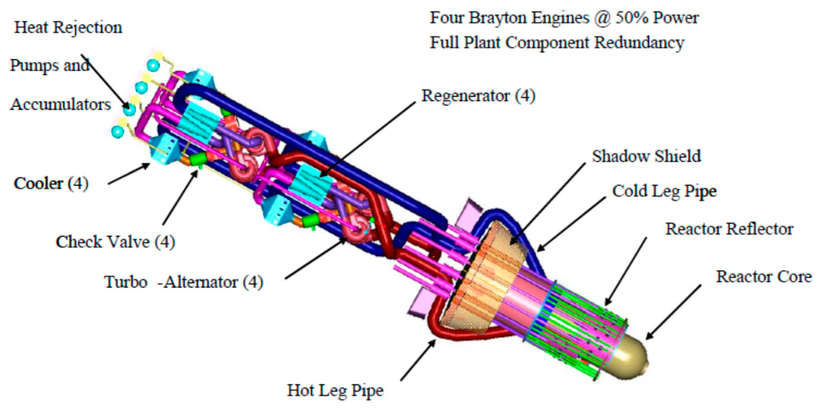
A reference base case system configuration has been developed, comprising a fast reactor cooled with a helium-xenon (78:22) gas mixture, both fixed and movable beryllium oxide reflectors, and highly enriched uranium oxide (UO2) fuel, later, UN and UC arranged in a hexagonal lattice of fuel pins mounted within a block. A boron-carbide safety pin was included to ensure the reactor remained subcritical through all phases of launch and ascent into orbit. A power conversion system using the Brayton cycle was specified for electric power generation. The Prometheus (2003) reactor module (Figure 1) base case was designed to provide 1-MW of thermal power, which would be converted to approximately 200 kW of electrical power over a 15-year mission duration. A schematic of the Prometheus Project reactor module is shown in Reference [9].
Generally, the structural materials had to operate for up to 20 years at high temperatures (1150 K) and moderate to high neutron fluences of 1021–1022 n/cm2 with no ability to inspect or repair plant components during the mission. Even though the project was cancelled in 2005 due to insufficient funding, the overall space nuclear power plant presented unique reliability and compatibility issues for the materials, which required further development.
The material classes designed for structural applications include refractory metal alloys, Ni-based super-alloys, Ti-based alloys, and silicon carbide (SiC). Refractory metal alloys and SiC were considered primarily for fuel cladding due to their high-temperature strength and creep resistance. All clad materials exhibit poor properties, which require further improvement, e.g., Nb-1Zr alloy exhibits insufficient creep strength, Nb and Ta alloys have poor oxidation tolerance for coatings, Mo-Re exhibits radiation-induced embrittlement, and the SiCf/SiC composite needs general development including joining. Ni-base super-alloys (IN 617) were considered for the pressure vessel and also for most of the plant components due to adequate temperature capability, a good overall balance of properties, and an established industrial manufacturing base for fabrication of complex components, such as heat exchangers and turbines. Ti-based alloys were considered for lower temperature plant components to reduce mass. The considered candidate materials for the reactor in Prometheus project are given in Table 3 [10]. The European research institutes are working on similar projects related to space flights and are pursuing high power space transportation, i.e., Democritos, Megahit, MARS/EUROPA INPPS (International Nuclear Power and Propulsion System) flagship, where a gas-cooled fast reactor system is considered. Recently, China published a study where a megawatt-class, the GFR was designed to provide 2.2 MWth power for space application [11]. The reactor concept adopts 90% enriched annular UO2 rods as the fuel and He-Xe mixture as the coolant. The thermal power is converted into electric power through Brayton turbines.
2.2. European GFR Program
A German feasibility study [12] concluded that the GFR with steel clad vented fuel pins was the system with the least required development. This reactor offered a performance comparable to that of the sodium breeder. Further developments included technical improvements such as the feasibility of large pre-stressed concrete pressure vessels for very high pressures (100–130 Atms), the use of partially roughened fuel element surfaces, and the development of new vanadium alloys with good creep properties under fast flux irradiation at high temperatures and the possibility of using gas turbine cycles. The effort to develop a European GFR was continued by the Gas Breeder Association. Several designs are given in Table 2. The initial GFR work was terminated in 1980 due to safety concerns associated with the low core thermal inertia. GFR development was revived by European countries, specifically CEA in the 1990s under the Generation-IV reactor development program. A major innovation that promoted the return of the European GFR.
2.3. ALLEGRO Reactor and Materials
As a reference concept (850 °C, 2 400 MWt), the original concept of the ALLEGRO GFR was designed in France by CEA, which is an alternative to the sodium fast reactor (SFR). Slovakia, Czech Republic, Hungary, Poland, and France are currently continuing to work on the ALLEGRO project [13], whose objective is to design, to build, and to operate the first 75 MW GFR Demonstrator-ALLEGRO. Since the ceramic fuel is still under development, stainless steel cladded MOX or UOX fuels were chosen for the first ALLEGRO core producing helium temperatures of 530 °C. The original design of the ALLEGRO consists of two helium primary circuits, and Decay Heat Removal (DHR) loops are integrated in a pressurized cylindrical guard vessel. The two secondary gas circuits are connected to gas-air heat exchangers.
The ALLEGRO reactor is supposed to operate not only as a demonstration reactor hosting GFR technological experiments, but also as a test pad for using the high temperature coolant of the reactor in a heat exchanger that generates process heat for industrial applications and a research facility that, thanks to the fast neutron spectrum, makes it attractive for fuel and material development as well as the testing of special devices and other research works.
The main objectives of the ALLEGRO project are the development of the following:
- GFR refractory fuels (UPuC, SiCf/SiC cladding), and structural materials for a core that can withstand both high temperatures and high neutron fluxes,
- Helium-related technologies (components, instrumentation, purification)
- Safety technical issues and corresponding safety approach framework.
There are several categories of materials for structural applications in the ALLEGRO design: fuel cladding, core structure (e.g., core block and structural joints), and pressure boundary (e.g., reactor vessel, piping, and plant components).
2.3.1. Reactor Vessel
Compared to a pressurized water reactor (PWR), the GFR shall operate at high-normal/off-normal service temperatures: up to 450 to 500 °C at 5 to 8 MPa and the fluence up to 1 × 10¹⁹ n.cm2. 9Cr steels are promising candidate materials for the reactor pressure vessel of high temperature gas-cooled reactors. In fact, the chemical composition of these materials has been continuously optimised by adding alloying elements, providing the formation of carbides (in particular, T91, 9Cr-1Mo VNb or T92, and 9Cr-0.5Mo WVNb). These materials have a martensitic structure. The metallurgy of these steels provides a good compromise between creep properties and toughness. These steels have excellent irradiation behavior. The microstructure of steels remains stable and they exhibit the sufficient toughness in typical irradiation conditions of rapid reactors: 400 to 550 °C and up to 100 dpa.
2.3.2. High-Temperature Components
For temperatures above 800 °C, such as those targeted in GFRs and HTRs, no steel can be employed, except for high Ni austenitic steels, such as the alloy 800. In this case, Ni-based alloys (e.g., Inconel 617, Haynes 230, and Hastelloy XR) are suitable options for components outside the core, particularly heat exchangers (not only for GFRs and HTRs) and power conversion systems. However, these alloys suffer from severe irradiation embrittlement and swelling. Therefore, their use in the core can be critical. Structural material behaviour important for reliable performance includes the following.
- Thermal creep in multiple product forms, such as thin-walled tubing, thin sheet, thick plate, and rod or bar,
- Fatigue, creep-fatigue resistance, and creep crack growth resistance,
- Resistance to irradiation effects such as creep, swelling, and embrittlement,
- Resistance to environmental degradation from helium impurities: fuel, fission products, transmuted elements, and thermal aging, and
- Good fabricability, welding, and post-weld thermal annealing, dissimilar metal joining.
Inconel Alloy 617 (UNS N06617) 52Ni-22Cr-13Co-9Mo is the leading candidate material for the intermediate heat exchanger in GFRs. An ASME Task Group on Alloy 617 Qualification has drafted a Code Case for Alloy 617 to allow construction of components [14]. The excellent high-temperature performance of Alloy 617 was published elsewhere [15].
2.4. GFR-Summary
This chapter summarizes findings related to materials development for GFRs including the space program from 1970 up to the present. Several groups of materials based on their deployment in the reactor have been selected. Nickel-based alloys (Alloy 617, Haynes 230, Alloy 625,690) and titanium-based alloys for the high temperature out of core components. The development approach is to rely on technologies developed for the VHTR for structures, materials, components, and power conversion systems. A qualification Code Case for Alloy 617 to allow construction of components has been submitted. Due to high irradiation doses, other heat-resistant materials need to be considered for in-core applications and insulation. The spectrum is very wide, ranging from refractory metals (e.g., molybdenum or vanadium) to ceramics. The latter generally offers very attractive properties in terms of both the stability to high temperatures and the resistance against wear and corrosion/erosion. However, both properties are counterbalanced by brittleness and a core design. Materials and their manufacturing technologies including fuel cladding are still being developed. Advanced ceramic or metallic refractory materials, which can be considered for cladding or other applications in GFRs to mitigate corrosion effects, include ODS-Mo, high entropy alloys (HEAs), and MAX phases. The high entropy alloys (HEAs) have attracted great attention in recent years as very promising materials with the high resistance against radiation damage and high-temperature properties. The main candidate for GFR cladding, which has also been extensively studied is the ceramic composite SiCf/SiC, i.e., silicon carbide fibres in the silicon carbide matrix. However, the design rules and joining technique of SiCf/SiC cladding also need to be developed.
3. The Characterization and Testing of SiCf/SiC
The experimental out of pile, a closed-circuit, the high-flow velocity High Temperature Helium Loop 2 (HTHL-2) for materials testing located at Centrum Výzkumu Řež, Czech Republic (CVR) is an improved version of the currently operated loop HTHL-1, with the experimental MATChannel (see Figure 2). A detailed description of the HTHL loops has already been published [7,16]. The MATChannel is specifically developed for the study of cladding material behaviour under simulating GFR conditions (high temperature, pressure, and velocity of helium).
A high-temperature corrosion experiment (900 °C, 5 MPa, 90 m/s, 500 h) has been carried out in the HTHL-2 loop with samples of SiCf/SiC aiming to study potential erosion of the fuel pin clad material. The major part of the erosion in GFR will be caused by the high velocity (90 m/s) and high temperature helium gas. The composition of impurities in the impurity-controlled helium environment is specified in Reference [17].
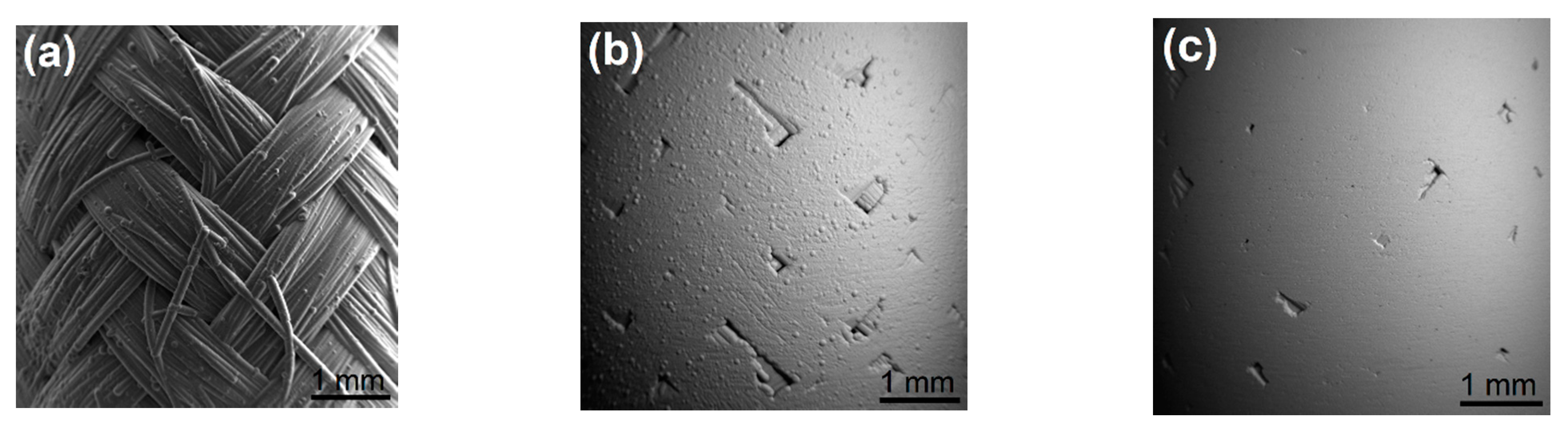
Samples of SiCf/SiC materials fabricated by French Atomic Energy Commision (CEA) with different degrees of mechanical pre-damage and different degrees of surface roughness have been selected and exposed to a high-temperature helium environment [18]. The result is shown in Figure 3. SiCf/SiC clad sections are based on a 2D texture of three successive layers including one layer of filament winding on two layers of 2D braiding that are added. Pyrocarbon coating is infiltrated through the texture by chemical vapor infiltration (prior to SiC infiltration) with the objective of 30–50 nm thickness. SiC infiltration is made by CVI in two steps.
Samples of SiCf/SiC l after the 500-h test in the HTHL-2 exhibited a dark blue color at the surface and was later determined as the silicon oxide layer. The evaluation of weight changes was in a range from 0 to 0.04 mg/cm2. The microstructure and chemical composition of the surface SiCf/SiC samples were inspected by SEM/EDX. Special attention was paid to the observation of the cracks on the pre-damaged samples. Improvement of the oxidation resistance of the SiCf/SiC composites was addressed through the design of innovative multi-layered interphases [19] and self-healing multi-layered matrices. The effects of oxygen diffusion through the cracks depend on the matrix and substrate. If the matrix is an oxidizable material, such as SiC, which attracts oxygen, oxygen diffusion through the cracks will react with the matrix and possibly seal the crack. Nevertheless, there was no healing of cracks due to oxidation of the surface observed.
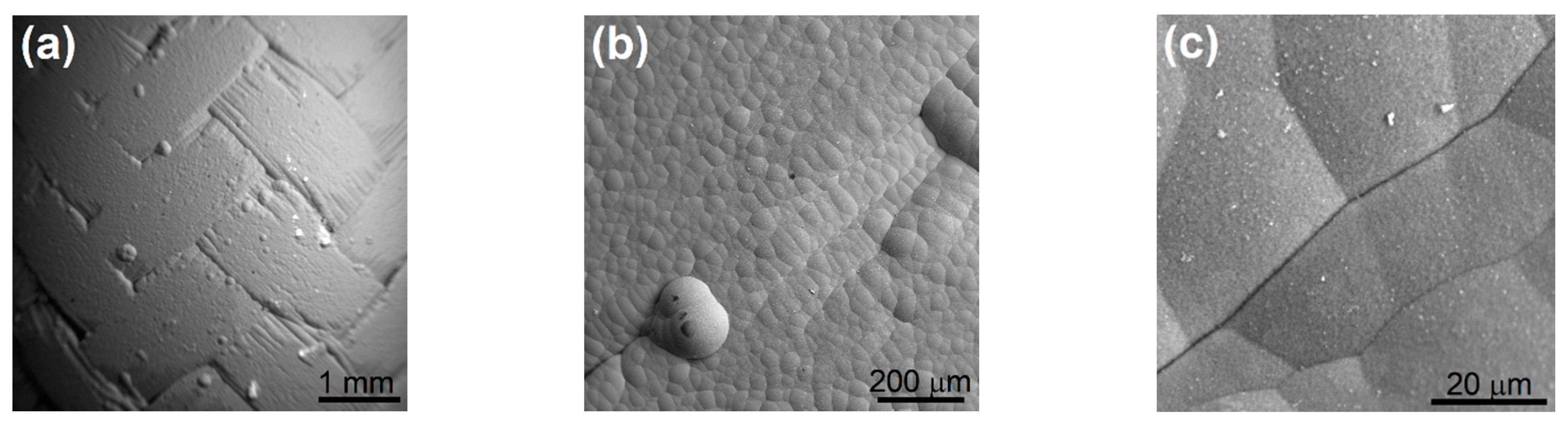
Figure 4 presents the surface of the sample CVR SiC L2-17C, after the exposure at 900 °C, at 90 m/s for 500 h at different magnifications. The content of oxygen on the sample surface after the exposure increased four times, in comparison with the oxygen content in as-received samples. The oxidation of SiC is of interest due to its two different oxidation regimes that depend on its crystallographic form, the total pressure, and the partial pressure of the oxidant in the medium. If the oxidant partial pressure is high enough, the oxidation is passive and a protective, dense, and homogenous layer of SiO2 forms on the material surface. In contrast, if the oxidant partial pressure is too low, the oxidation is active, and a gaseous oxide forms. In this case, SiC is not protected and loses mass.
4. High Entropy Alloys for Nuclear Application
4.1. Radiation Damage
Neutron irradiation during operation of the nuclear reactor introduces Frenkel pairs (pairs of vacancy and interstitial) created in primary knock-on atom (PKA) cascades. In order to produce a stable Frenkel pair, a minimum kinetic energy Ed called the displacement threshold energy has to be transferred from a projectile particle to the host lattice atom. The Ed value depends on the host material and also on the crystallographic direction. Direction-averaged threshold energy in metals falls into the range of 15–90 eV [20,21]. For example, Ed = 40 eV for Fe [21]. The Norgett-Robinson-Torrens (NRT) [22,23] model can be used to evaluate the radiation damage expressed as the displacement per atom (dpa) produced by different energetic particles including neutrons. The number ND,NRT of displaced atoms in an irradiated material can be calculated within the NRT model, as follows.
where E denotes the kinetic energy of the reaction recoil, which is transferred to a primary knock-on atom (PKA) by an elastic collision. It was shown by computer simulations [24] that ballistic atomic collisions induced by an incident energetic particle cause displacement of a very large number of atoms in a short time scale of the order of 0.1–1 ps [25]. However, when the cascade cools down, the majority of displaced atoms returns to their original positions. Hence, the number of radiation-induced defects is much lower than the number of atom replacements. This athermal recombination has been taken into account in the corrected (arc-dpa) model [26]. The arc-dpa approach quantifies the total number of primary defects (vacancy-interstitial pairs) ND,arc, which survived the local annealing of the hot recoil cascade during first 10–100 ps after the initiating of the nuclear reaction [27]. To account for the athermal recombination, the arc-dpa model includes the defect generation efficiency and the number of displaced atoms given by the NRT model is modified into the following form [26].
The defect generation efficiency function has been determined using molecular dynamic simulations [26] and incorporated into the NJOY-2012 code [28] for simulation of neutron-induced damage. Recent comparison of arc-dpa model prediction with direct measurement of vacancy concentration by positron annihilation spectroscopy (PAS) [29] revealed that the arc-dpa model gives a reasonable prediction of radiation damage for neutron-irradiated and proton-irradiated Fe at low temperatures (T < 10 K).
In real materials, the athermal recombination is followed by thermally activated evolution and recovery of radiation-induced defects taking place in a broad time scale from ns to years, depending on the temperature at which the material is stored. Due to the thermal recovery, the actual concentration of radiation-induced defects in materials irradiated at ambient temperature or even at elevated temperatures can be significantly lower than the arc-dpa prediction [29]. The extent of the thermal recovery depends on the mobility of defects at the irradiation temperature. Moreover, irradiation-induced defects migrating in the material interact with each other, agglomerating into vacancy clusters and forming vacancy or interstitial loops [30,31,32]. In alloys, the irradiation-induced defects interact with various solutes forming complexes [33,34] and facilitating solute clustering [35,36,37] and segregation [38,39]. A comprehensive theoretical approach allowing for modelling and prediction of the thermally-activated recovery of radiation-induced defects is not available yet.
Since irradiation in nuclear reactors occurs at elevated temperatures, (≈300 °C in the current Gen III light water reactors) vacancies and interstitials are mobile and the long-range diffusion of point defects is possible. This facilitates vacancy-assisted solute segregation and clustering and development of radiation-induced nano-precipitates. Moreover, migrating vacancies agglomerate into immobile clusters, which results in void swelling. These processes occur in the conventional nuclear materials, including ferritic steels [35,40], austenitic stainless steels [41], and zirconium alloys [42], and represent severe limitation of the lifetime of the current Gen III reactors. Structural materials for advanced GFR nuclear systems must withstand significantly higher neutron doses, higher temperatures (see Table 1), and an extremely corrosive environment. This requires new structural materials to replace conventional steels and zirconium alloys.
4.2. High Entropy Alloys
In recent years, high-entropy alloys (HEAs) attract great attention as very promising materials with high resistance against radiation damage. HEAs [43] represent a new paradigm in materials science. Contrary to traditional alloys based on one or two principal elements, e.g., Fe for steels or Zr for zirconium alloys, HEAs are composed of at least five principal elements with the concentration of each element being between 35 and 5 at.% [44]. The molar configurational entropy of an ideal random solid solution (SS) consisting of N constituents is:
where ci is the atomic concentration of the i-th constituent and R is the universal gas constant. The configurational entropy increases with a growing number of constituents. For an alloy consisting of N elements in the equimolar concentration (), the configurational entropy becomes Since SSS increases with a growing number of constituents, the typical feature of HEAs is a high entropy SSS > 1.61 R. The molar Gibbs energy at the temperature T is G = H − TS, where H is the molar enthalpy. For an ideal random SS, the enthalpy HSS = 0 and the Gibbs energy becomes . For a perfectly ordered intermetallic (IM) phase, the configurational entropy SIM ≈ 0 and the Gibbs energy equals to the enthalpy Hence, the difference of the Gibbs energy between random SS and a competing IM phase is:
If TSSS is higher than-HIM enthalpies for all possible IM phases, the random SS represents the thermodynamically equilibrium phase of the alloy. Since multi-component HEAs are characterized by high SSS values, they frequently form random SS where atomic sites in simple fcc and bcc structure are randomly occupied by atoms of the constituents that maximize the configurational entropy. This peculiar structure results in unique physical properties, which can be summarized into four so called core effects [43].
(i) The high entropy. Because of high configurational entropy, HEAs often exhibit random SS even at room temperature. Random occupation of lattice sites by various elements is the key feature of the HEA structure. Random SS seems to be less sensitive to radiation damage compared to conventional alloys due to a unique “self-healing” mechanism of irradiation-induced defects [45]. Moreover, the high configurational entropy might influence the recombination of Frenkel pairs and the diffusivity of a point defect in irradiated materials [46]. The configurational entropy of alloy consisting of N elements is maximized for the equimolar composition of the elements. For this reason, many HEAs have an equimolar composition.
(ii) Lattice distortions. Different atom sizes of HEA constituents cause severe lattice distortions. The displacement of each atom depends on the type of surrounding atoms. Since atoms of different sizes and chemistries reside in the lattice, which is not specifically designed for each of them, the atoms are under considerable stresses, which distort the lattice and increase the lattice friction for dislocations [45,47]. The magnitude of lattice distortions can be expressed using the atomic misfit parameter [43].
where ri is the atom radius of the i-the element and is the composition-weighted mean atom radius . Lattice distortions increase the hardness of HEAs and reduce their electrical and thermal conductivity [44]. Moreover, lattice distortions are expected to have a strong influence on the resistance against radiation damage. Since lattice distortions of radiation-induced vacancies are attracted to the vicinity of “big” atoms with a higher atomic radius while interstitials are attracted to “small” atoms with a lower atomic radius. Hence, point defects are captured in local lattice distortions and their mobility is substantially reduced. As a consequence, the development of solute clusters and agglomeration of vacancies is suppressed. Due to this phenomenon, it is expected that HEAs may exhibit high resistance against radiation-induced swelling and solute segregation damage, making them suitable for use in advanced nuclear reactors. Although there is a lack of data about radiation resistance of HEAs, results of a few pioneering studies performed so far support this picture [45,46,48,49,50,51,52].
(iii) Sluggish diffusion. In HEAs, each lattice site is surrounded by different atoms and, therefore, each site has a different bond configuration and different lattice potential energy [44]. It has been proposed that this results in sluggish diffusion in HEAs [53,54]. This hypothesis has not been verified experimentally and remains controversial. For example, the diffusion coefficient of Ni at 1173 K in the CoCrFeMn0.5Ni HEA was lower than that in FeCr15Ni20 stainless steel [55]. However, investigations of 63Ni tracer diffusion [56] in CoCrFeMnNi HEA revealed that diffusion coefficient decreases with an increasing number of constituents only when the comparison is done using a normalized homologous temperature Tm/T. Diffusion is strongly related to vacancies present in a system. The correlation between vacancy concentration, atom diffusion, and oxidation rate has been intensively discussed in previous studies [55,56,57]. The key factor influencing the diffusion in HEAs is the previously mentioned trapping of vacancies in the vicinity of big atoms, which may alter the correlation factor between atomic jumps [58].
(iv) The cocktail effect expresses the benefit of the synergetic nature of HEA development where the final result is unpredictable and greater than the sum of individual constituent parts [59]. HEAs provide a huge number of combinations, resulting in various properties. Hence, there is a large space to be explored. Composition of HEAs can be optimized to achieve properties tailored for particular applications. Note that the “trial-and-error approach” by means of a random mixing of various elements is extremely inefficient when taking into account the enormous number of possible combinations. The development of HEAs with enhanced functionality requires a knowledge-based approach using advanced thermodynamic modelling [60] and atomistic methods [61].
Several HEA families have been discovered so far. (i) 3d transition metal HEAs [53,62,63] containing Al, Co, Cr, Cu, Fe, Mn, Ni, Ti, V, and having the fcc structure, (ii) refractory metal HEAs with the bcc structure, containing Cr, Hf, Mo, Nb, Ta, Ti, V, W, Zr with the possible addition of Al [64,65,66,67,68,69], (iii) lanthanide 4f HEAs [70] consisting of Dy, Gd, Lu, Tb, Tm, Y, and having the hcp structure, (iv) low density HEAs [71,72] containing Al, Be, Li, Mg, Sc, Si, Sn, Ti, and Zn, (v) complex concentrated brasses and bronzes [73] containing Al, Cu, Mn, Ni, Sn, and Zn, and (vi) precious metal HEAs consisting of Ag, Au, Co, Cr, Cu, Ni, Pd, Pt, Rh, Ru, and Au [74].
4.3. Radiation Damage in High Entropy Alloys
Investigations of 3d transition metal HEA CoCrCuFeNi thin films with the fcc structure under 2 MeV electrons’ irradiation confirmed the high stability of this alloy against the radiation damage [48]. The fcc phase remained as the main constituent phase up to the high dose of 40 dpa. The study of equi-atomic CoCrFeNi HEA in situ irradiated with electrons showed that the growth of radiation-induced defects in the HEA was ≈40 times slower than in pure Ni [50]. Moreover, it was found that radiation-induced volume swelling of AlxCoCrFeNi HEA irradiated with 3 MeV Au ions up to 50 dpa was lower than those of conventional nuclear materials under similar irradiation [49]. Investigations of Co-free CrFeMnNi HEAs subjected to ion irradiation at elevated temperatures 400–700 °C revealed less radiation degradation compared to conventional austenitic Fe-Cr-Ni or Fe-Cr-Mn alloys [46]. In particular, CrFeMnNi HEA exhibited better swelling resistance and the irradiation-induced segregation near grain boundaries was found to be significantly suppressed in the irradiated HEA [46]. From inspection of the available data, it seems that the performance of HEAs under irradiation is superior to amorphous and nanocrystalline alloys. While in the amorphous alloys, irradiation usually leads to the formation of nano-precipitates and, in nano-structured alloys, solute segregation at grain boundaries takes place. HEAs exhibit good structural and phase stability [51,52,53]. Moreover, the void swelling [75] and the radiation-induced segregation phenomena [76,77], which are responsible for radiation degradation of steels and zirconium alloys seem to be suppressed in HEAs due to the capture of radiation-induced vacancies. Hence, according to these pilot studies, HEAs can be considered as promising materials for GFR systems. In particular, some refractory metal HEAs are very promising for applications in fusion and Gen IV fission applications due to their high strength, fracture toughness, oxidation resistance, and creep strength at elevated temperatures.
4.4. Our Investigations of Radiation Damage in Refractory Metal High Entropy Alloys
Radiation-induced damage has been studied predominantly in 3d transition metal HEAs so far [45,48,52,76,77,78]. There is almost a complete lack of information about radiation damage in refractory metal HEAs, which represent promising structural materials for high-temperature applications. In order to fill this gap, investigations of refractory metal HEAs irradiated by energetic protons have been performed in the present work.
4.4.1. Selection of Refractory Metal Alloys
Several alloys consisting of refractory metal elements Hf, Nb, Ta, Ti, and Zr have been prepared by arc melt casting. Casting was performed six times and the sample was flipped for each melt to mix the elements thoroughly and to suppress chemical heterogeneities. Dimensions of cast ingots were approximately 100 × 30 × 10 mm3. The chemical composition and basic properties of samples studied are summarized in Table 4. The five element HEA alloy HfNbTaTiZr developed by Senkov et al. [79] was chosen for its excellent mechanical properties, consisting of a favourable combination of high strength and sufficient ductility. Since the HfNbTaTiZr alloy contains Hf, an element with a high absorption cross section for epithermal neutrons is not suitable for applications inside nuclear reactors. However, it represents a good model system for investigation of radiation damage in refractory metal HEAs. In order to suppress undesired absorption of epithermal neutrons, Hf has to be omitted or replaced by another element with a lower neutron absorption cross-section. For this reason, Hf-free four element alloys NbTaTiZr and Nb0.5TaTiZr1.5 have been included in the present study. One can see in Table 4 that NbTaTiZr exhibits the yield strength comparable to HfNbTaZr, but roughly half ductility. The Nb0.5TaTiZr1.5 alloy was designed with the aim to achieve a high magnitude of lattice distortions, leading to a high value of a misfit parameter of 5.22%. As shown in Table 4, the Nb0.5TaTiZr1.5 alloy exhibits a high hardness, but it is rather brittle. The sample of the Nb0.5TaTiZr1.5 alloy broke down during the tensile test before reaching the yield point. Due to its brittleness, Nb0.5TaTiZr1.5 is not suitable for structural applications. However, it is an appropriate model alloy for testing the influence of lattice distortions on the radiation damage. A ternary alloy NbTaTi was investigated as well. Since Nb, Ta, and Ti have similar atomic radii, the magnitude of lattice distortions in the NbTaTi alloy is rather low (=1.10%). The aim of the present study was two-fold: (i) to characterize the radiation damage in refractory metal alloys and (ii) to elucidate the effect of lattice distortions on the formation and the development of radiation-induced defects.
4.4.2. Experimental Details
The alloys were irradiated with 2.9 MeV protons at room temperature using a Tandetron accelerator. The samples were irradiated in several steps with the fluence gradually increasing from 1015 to 1016 cm–2. The samples were investigated after each irradiation step to study the development of irradiation-induced defects with increasing fluence.
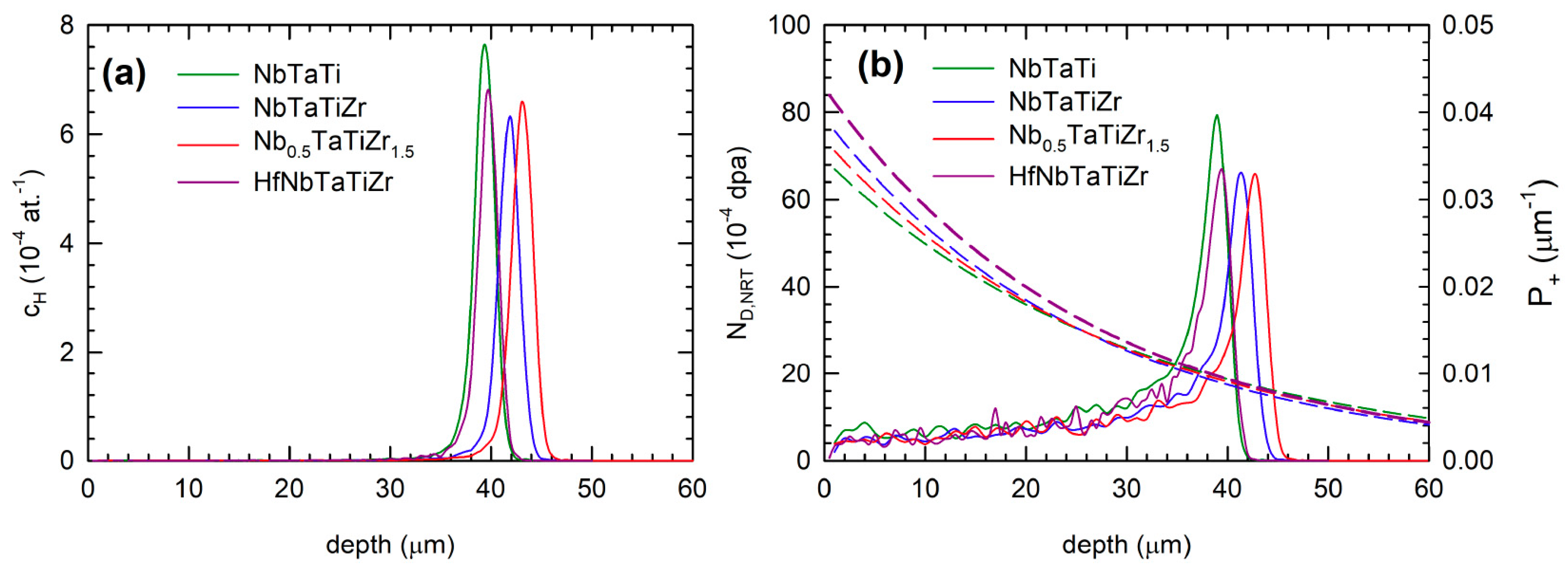
Figure 6 shows the results of the simulation of proton irradiation using the SRIM code [81]. The depth profile of implanted H+ ions is plotted in Figure 6a, while Figure 6b shows the concentration profile of irradiation-induced vacancies calculated using the NRT model [22,23]. From inspection of Figure 6a, one can conclude that the peak of the concentration of H+ ions is located in the depth of 35–45 µm for the alloys studied. The region modified by irradiation extends from the surface up to the depth of 40–48 µm with the peak damage located in the similar depth as that of the maximum concentration of H+ ions (see Figure 6b).
Positron annihilation spectroscopy (PAS) [82] was employed for the characterization of irradiation-induced defects in the alloys studied. PAS represents a well-established technique for the investigation of open-volume defects like vacancies, vacancy clusters, vacancy-solute complexes, dislocations, etc. [83]. A measurement of positron lifetime (LT) enables the identification of radiation-induced defects and the determination of their concentrations [29,33,84].
The positron source was made by deposition of 2 µl of 22NaCl water solution (iThemba Labs) with activity of ≈ 1.5 MBq on a 2 µm thick Mylar foil. The diameter of the positron source spot was 2 mm. It was always sandwiched between two specimens of the alloy studied with the irradiated face oriented toward the positron source. Positrons emitted by 22Na decay have a continuous energy spectrum with the mean value of around 200 keV and their implantation profiles P+ into the refractory metal alloys studied are plotted in Figure 6b. Using the implantation profile, one can calculate that approximately 80% of positrons are stopped and annihilated in the region up to the depth of ≈45 µm, which was affected by H+ irradiation. Remaining positrons penetrated deeper into the samples and were annihilated in the region, which was not damaged by irradiation. A digital spectrometer [85] with the time resolution of 145 ps (FWHM of the resolution function) was employed for PAS investigations. At least 107 positron annihilation events were accumulated in each lifetime (LT) spectrum. Decomposition of LT spectra into individual components was performed using the PLRF code, version 19 [86]. The source contribution consisted of two weak components, which came from positrons annihilated in the source spot and the covering Mylar foil and exhibit lifetimes of ~368 ps and ~1.5 ns and intensities of ~8% and ~1%, respectively.
The microstructure of alloys studied was examined by scanning electron microscopy (SEM) using FEI Quanta 200F microscope equipped with an energy dispersive X-ray spectroscope (EDS) for local chemical composition analysis.
4.4.3. Results
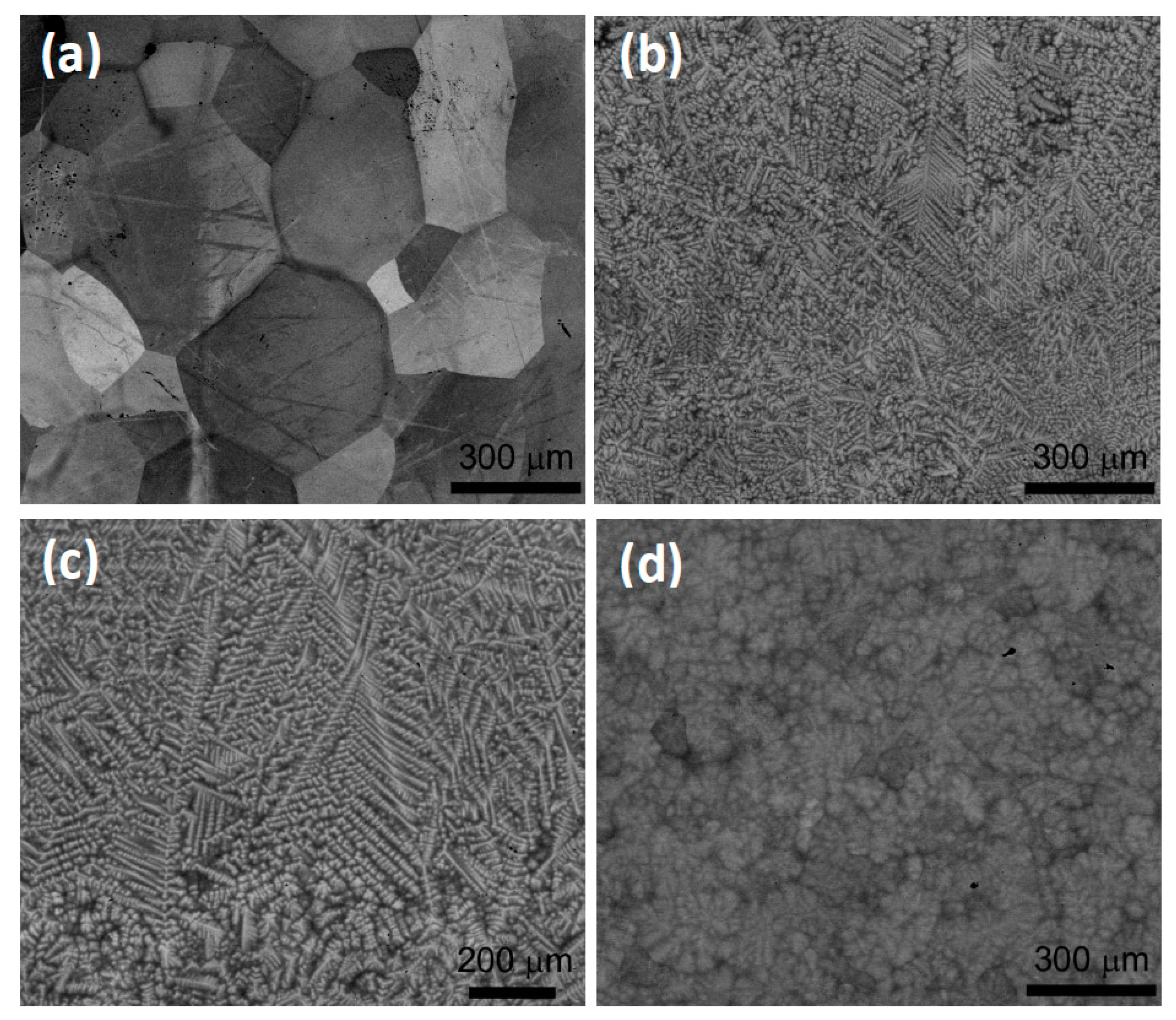
The microstructure of virgin alloys is shown in Figure 7. Chemical composition determined by EDS is consistent with the nominal composition. The mean grain size was found to be around 500 µm for all alloys. The ternary alloy NbTaTi consists of the single phase SS (Figure 7a) while the four component alloys NbTaTiZr and Nb0.5TaTiZr1.5 exhibit a typical dendritic structure (see Figure 7b,c), respectively. The bright regions in Figure 7b,c are enriched in Ta and are separated by dark regions enriched in Zr. The concentration of Nb and Ti is approximately uniform. In the five-element alloy HfNbTaTiZr, the dendritic segregation was found as well (see Figure 7d). However, it is significantly lower compared to NbTaTiZr and Nb0.5TaTiZr1.5 alloys.
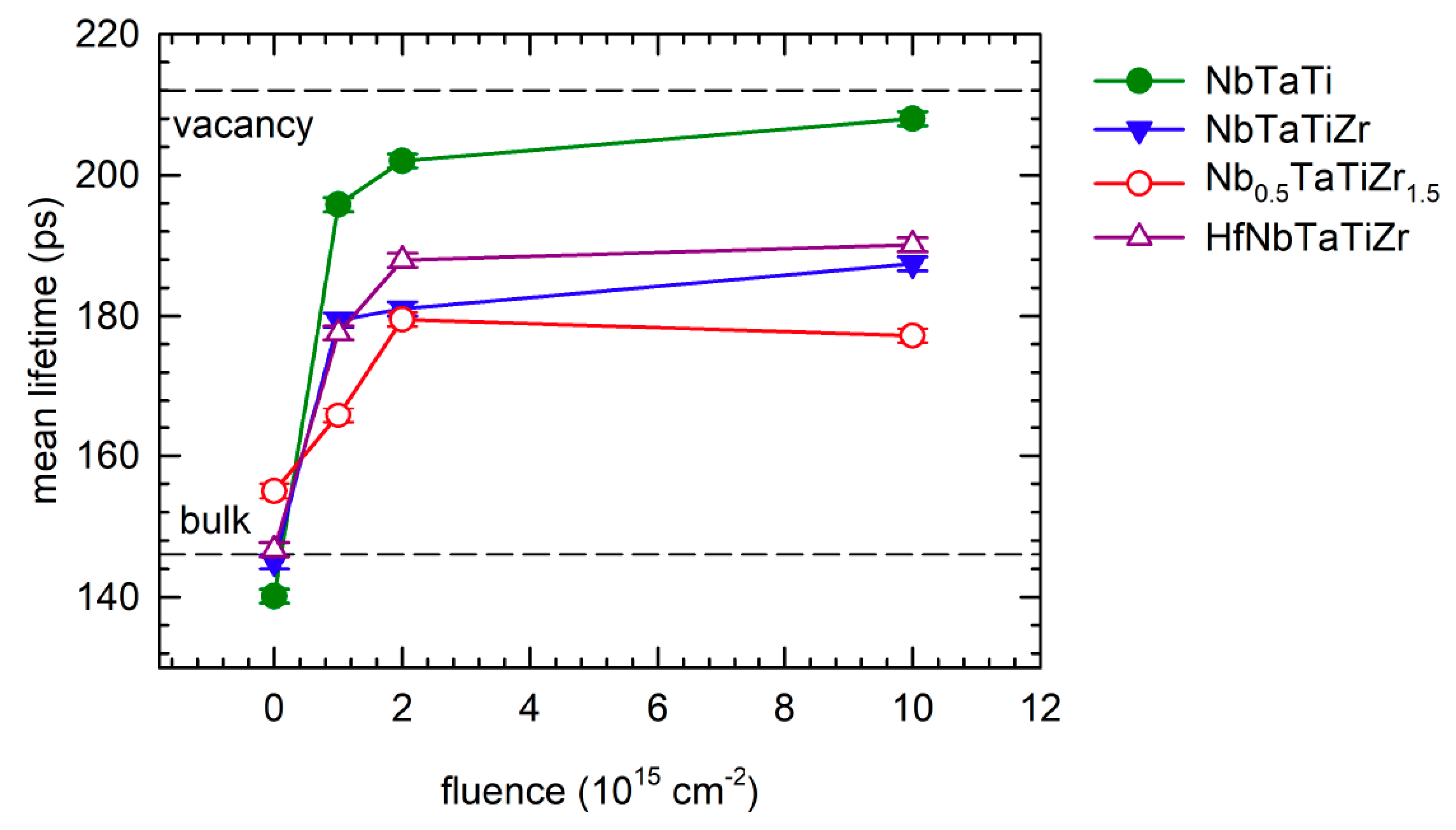
Figure 8 shows the development of the mean positron lifetime with increasing irradiation fluence. The mean positron lifetime is a robust parameter, which is only slightly affected by correlations between the fitting parameters. It is useful for observation of trends occurring during irradiation. The virgin samples exhibit single component LT spectra indicating that positrons are annihilated in a single state. The virgin state of the alloys studied is characterized by the lifetime in the range of 140–155 ps corresponding to the bulk lifetime, i.e., the lifetime of free positrons not trapped at defects [87]. Hence, the concentration of defects in these alloys is very low and virtually all positrons are annihilated in the free state.
Proton irradiation led to an increase of the mean positron lifetime due to the formation of radiation-induced defects. The mean lifetime of all alloys increases with increasing fluence, indicating that the concentration of irradiation-induced defects grows with rising fluence. The most pronounced increase of the mean positron lifetime was observed in the NbTaTi alloy (see Figure 8). For the highest fluence of 1016 cm−2, the mean lifetime approaches 210 ps corresponding to the lifetime of positrons trapped in monovacancy, testifying that the majority of positrons is trapped in vacancies. The NbTaTiZr and HfNbTaTiZr alloys exhibit a comparable increase of the mean positron lifetime, but it is remarkably lower than that in the NbTaTi alloy. The lowest increase of the mean positron lifetime was observed in the Nb0.5TaTiZr1.5 alloy where the magnitude of lattice distortions is the highest among the alloys studied, as reflected by the highest value of the misfit parameter (see Table 4).
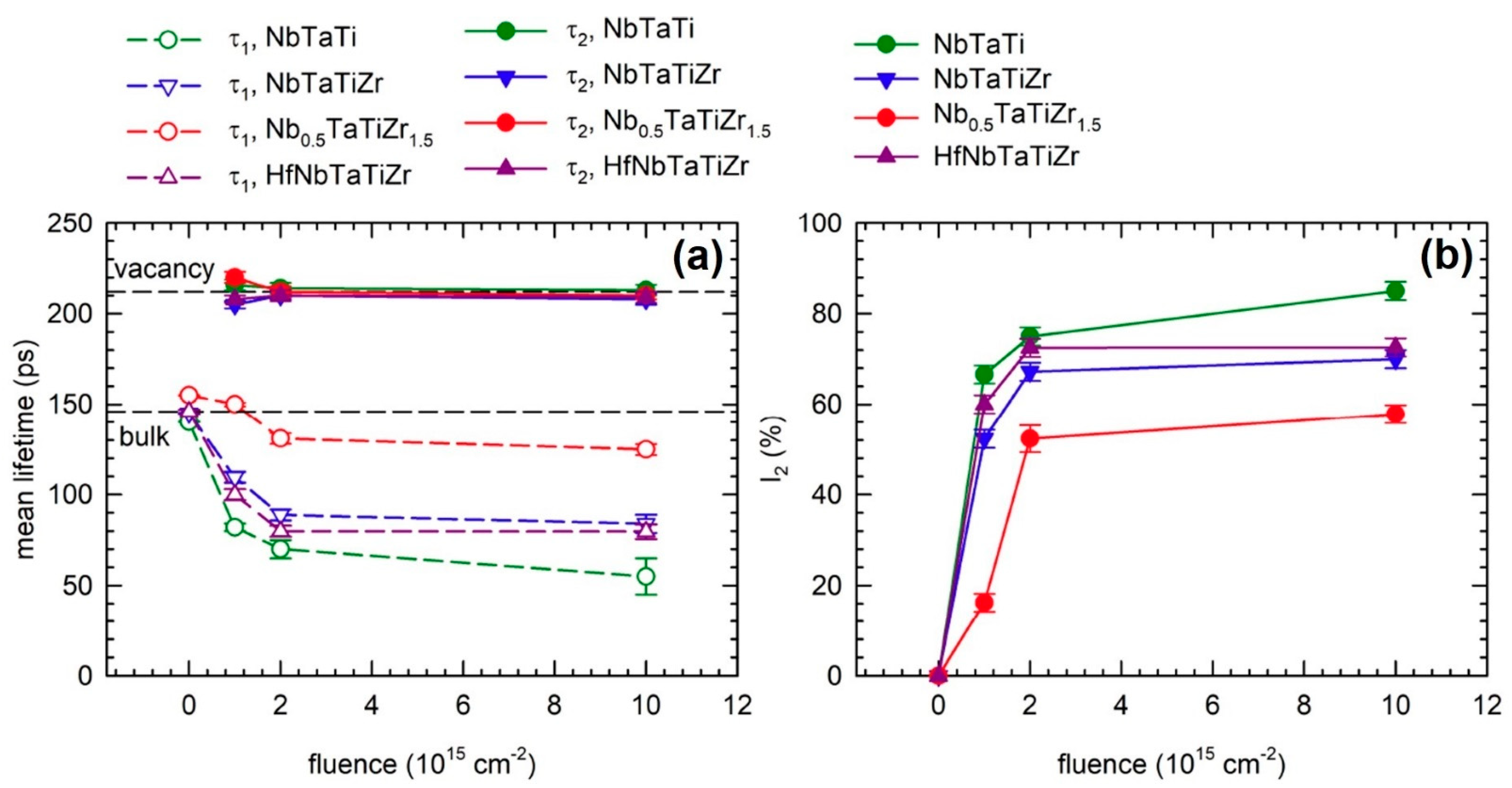
More information can be obtained by the decomposition of LT spectra into individual components. Figure 9a shows the development of lifetimes resolved in LT spectra as a function of the irradiation fluence. LT spectra of all irradiated alloys can be well described using two exponential components (except for the source contribution). The first component with shorter lifetime τ1 comes from free positrons not trapped at defects, while the component with longer lifetime τ2 can be attributed to positrons trapped at irradiation-induced defects. The lifetime τ2 is around 210 ps for all irradiated samples studied. It indicates that proton irradiation introduced monovacancies. No agglomeration of vacancies into vacancy clusters was observed since the lifetime τ2 remains approximately constant with increasing fluence.
The intensity I2 of positrons trapped at defects is plotted in Figure 9b and increases with increasing fluence, testifying the increasing concentration of irradiation-induced vacancies. The concentration of irradiation-induced vacancies differs in individual alloys as reflected by different values of I2. The highest concentration of vacancies (the highest I2 value) was observed in the ternary alloy NbTaTi characterized by the lowest atomic misfit parameter δ = 1.05%. On the other hand, the Nb0.5TaTiZr1.5 alloy with the highest misfit parameter δ = 5.22% exhibits the lowest concentration of irradiation-induced vacancies (the lowest I2 value). Lattice distortions likely increase the PKA threshold displacement energy. As a consequence, HEAs with a high magnitude of lattice distortions exhibit better resistance against radiation damage.
4.4.4. Discussion
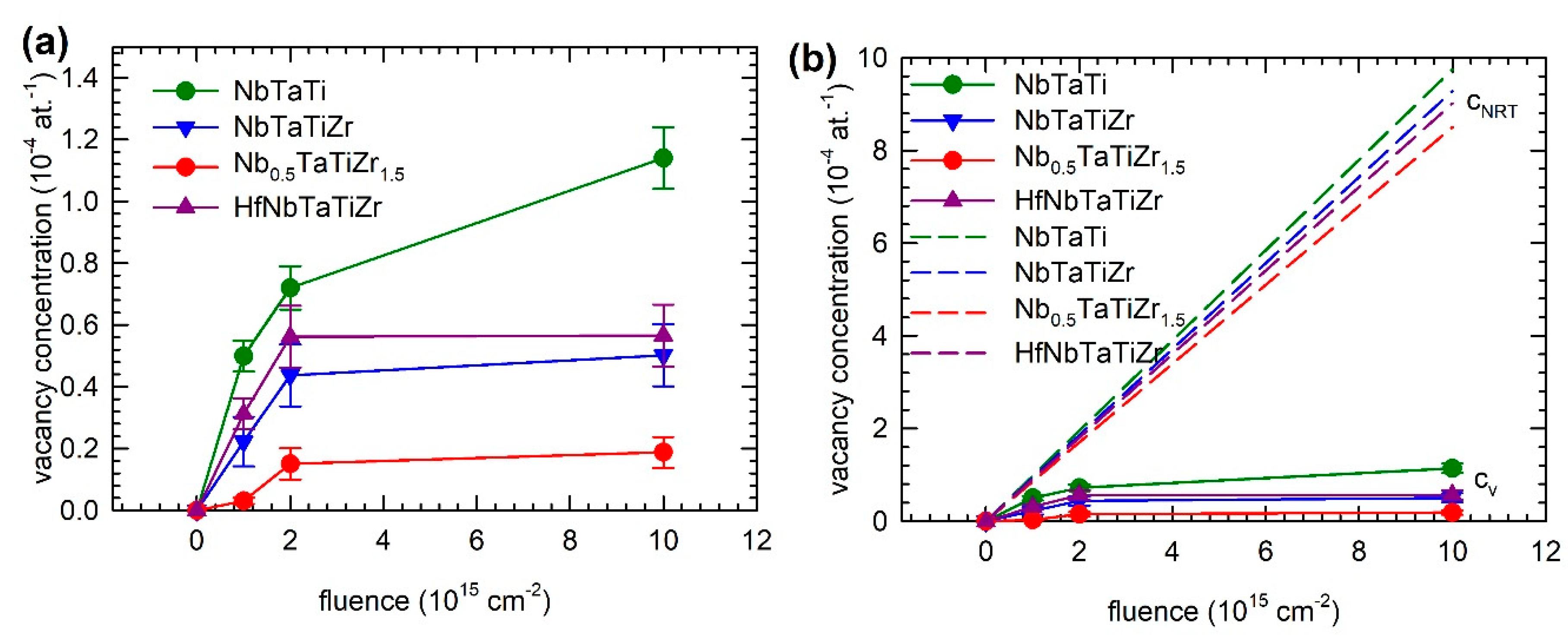
Figure 10a shows the development of the concentration of vacancies cv estimated from PAS data using the two-state simple trapping model [88]. The specific positron trapping rate for vacancies of 1014 at. s–1 was used [89]. The concentration of vacancies increases with growing fluence and the saturation can be observed in the alloys NbTaTiZr, Nb0.5TaTiZr1.5, and HfNbTaTiZr. The highest concentration of irradiation-induced vacancies was observed in the NbTaTi alloy with the lowest magnitude of lattice distortions while the alloy Nb0.5TaTiZr1.5 with the highest magnitude of lattice distortions exhibit the lowest concentration of vacancies. Hence, the concentration of irradiation-induced vacancies decreases with increasing magnitude of lattice distortions. From the depth profile of vacancy concentration calculated within the NRT model using the SRIM code [81] (see Figure 6b), one can calculate the average vacancy concentration cNRT “seen” by positrons by integrating the overlap of the vacancy concentration profile ND,NRT calculated by SRIM and the positron implantation profile P+ over the depth from the surface z
This value is plotted in Figure 10b and compared with the concentration of vacancies of cv determined in the samples experimentally by PAS. From the inspection of the figure, one can conclude that the concentration of irradiation-induced vacancies calculated with the NRT model is roughly by one order of magnitude higher than the value observed experimentally in proton-irradiated alloys. It testifies that a significant portion of Frenkel pairs created by proton irradiation disappeared either during the athermal recombination phase in the time interval of 10–100 ps after the cascade or later by thermally activated diffusion of point defects to sinks. One can assume that vacancies, which are not bound to big atoms, are mobile and disappear by diffusion to sinks at grain boundaries and on the surface. Vacancies captured in the vicinity of big atoms (Hf, Zr) and interstitials trapped in the vicinity of small atoms (Nb, Ta) are likely immobile and remain anchored in the lattice.
This picture is supported by recent hybrid Monte-Carlo/molecular dynamics simulations of irradiation-induced defects in CuNiCoFe HEA [90]. The calculations revealed that irradiation-induced vacancies in CuNiCoFe HEA are less mobile than in pure metals. In pure metals, irradiation-induced vacancies agglomerate, forming larger and more stable clusters, while, in HEA, a steady state of defect creation and recovery is quickly established. Moreover, irradiation restores solid solution by randomizing elemental distribution. In particular, it provides thermal activation for de-mixing of Cu. As a consequence, Cu segregation, which is harmful for mechanical properties, is suppressed. Transmission electron microscopy investigations of Ni ion irradiated Fe-Ni-Mn-Cr HEA confirmed that radiation-induced solute segregation near grain boundaries is significantly suppressed compared to Fe-Cr-Ni and Fe-Cr-Mn austenitic alloys [46]. Moreover, it has been found that irradiated Fe-Ni-Mn-Cr HEA contains vacancy clusters of a lower size and higher density compared to the austenitic alloys [46]. It testifies to the reduced mobility of point defects in HEAs.
Hence, the present investigations of refractory metal alloys irradiated by protons confirmed the good radiation resistance of HEAs. It seems that good resistance against radiation damage is the common property of 3d transition metal and refractory metal HEAs. Radiation resistance of HEAs is directly related to the effect of lattice distortions, representing a typical feature of the HEA structure. Although data reported on ions implanted and electron irradiated HEAs as well as results for proton irradiated HEAs reported in the present work are promising, there is still a lack of data about neutron irradiation of HEAs. A systematic study of radiation damage caused by neutron irradiation is essential for evaluating the real potential of HEAs for applications in GFR.
5. Conclusions
In all aspects, the 60-year lifetime of the reactor requires a detailed and complex knowledge of the evolution of the material exhibited to the various constraints (irradiation, thermal, mechanical, and environmental) and modelling of its behaviour to guarantee the stability during the reactor lifetime. The material for the primary circuit must exhibit excellent thermal stability for a long operating time, moderate creep strength, and well-established metal working and welding techniques.
- Ni-based superalloys are considered to be candidate structural materials for GFR. Promising solid solution strengthened Ni-based super-alloys include 230, 617, and 800H alloys, in which all are high Cr- Ni-based alloys with varying additions and exhibit good strength at high temperatures. Nevertheless, there are several issues connected with Ni superalloys, which have to be solved, such as the corrosion/oxidation/erosion in impure helium.
- SiCf/SiC composites represent novel materials currently considered for the use in GFR core components, especially as a material for cladding and control rods of the GFR. As shown in the present work, SiCf/SiC composites exhibit very good high-temperature corrosion resistance. However, to use SiCf/SiC as a material for GFR components, it is necessary to have well-established testing standards, material codes, and also the joining technology and enough in-pile and out-of-pile data.
- HEAs represent a new class of materials with excellent mechanical properties and high oxidation resistance at elevated temperatures. Moreover, recent investigations revealed that HEAs exhibit very good resistance against radiation damage. Due to these reasons, HEAs are currently intensively studied as potential structural materials for GFR. The main advantages of HEAs can be summarized in the following points.
- -
- Lattice distortions being a characteristic feature of HEA increase the displacement threshold energy of PKAs. As a consequence, the formation energy of Frenkel pairs is increased in HEAs, which improves their radiation resistance.
- -
- The mobility of point defects in HEAs is significantly reduced by trapping of vacancies and interstitials in outward and inward local distortions of the lattice. As a consequence, the formation of voids and swelling are suppressed.
- -
- Radiation-induced solute segregation is suppressed in HEAs as well due to reduced mobility of radiation-induced vacancies.
- -
- A huge number of composition variants provides plenty of room for optimization of HEA compositions in order to achieve excellent resistance against the radiation damage as well as the high strength, good mechanical stability, and corrosion resistance.
- -
- Unique properties of HEAs are closely related to lattice distortions of which the magnitude can be tuned by varying the composition. Fundamental studies relating the magnitude of lattice distortions and radiation resistance are, therefore, crucial for understanding the mechanism of radiation damage in HEAs and for the development of new HEAs optimized for applications in nuclear reactors.
Author Contributions
Conceptualization, J.Č., J.K. and M.J. Methodology, J.Č. and J.S. Software, J.Č. Validation, M.J., O.S. and A.M. Formal analysis, M.J. and J.S. Investigation, J.Č. and J.K. Resources, J.K. and O.S. Data curation, A.M. Writing—original draft preparation, J.Č. and J.K. Writing—review and editing, M.J. and J.S. Visualization, A.M. Supervision, M.J. Project administration, O.S. and M.J. Funding acquisition, O.S., M.J. and J.S. All authors have read and agreed to the published version of the manuscript.
Funding
This work was financially supported by the Czech Technological Agency under the project TK01030153. Irradiation of high entropy alloys has been carried out at the CANAM (Centre of Accelerators and Nuclear Analytical Methods) infrastructure LM 2015056 supported by OP RDE, MEYS, Czech Republic, under the project CANAM OP, CZ.02.1.01/0.0/0.0/16_013/0001812.
Conflicts of Interest
The authors declare no conflict of interest.
References
- World Nuclear Performance Report 2019. Contify Energy News, October 2019.
- Available online: https://ec.europa.eu/eurostat/statistics-explained/index.php?title=Nuclear_energy_statistics (accessed on 19 November 2020).
- Hangbok, C.; Myunghee, C.; Ryan, H. Benchmarking DRAGON/PARCS Against KRITZ and FFTF Measurements. Nucl. Technol. 2019, 205, 486–505. [Google Scholar]
- Donne, E.D.; Wirtz, K. European GCFR Program Plans (KFK—1663); Gesellschaft für Kernforschung mbH: Darmstadt, Germany, 1972. [Google Scholar]
- Van Rooijen, W.F.G. Gas-Cooled Fast Reactor: A Historical Overview and Future Outlook; Science and Technology of Nuclear Installations; Hindawi Publishing Corporation: London, UK, 2009; Volume 2009, p. 965757. [Google Scholar]
- Melese-d’Hospital, G.; Simon, R.H. Status of gas-cooled fast breeder reactor programs. Nucl. Eng. Des. 1977, 40, 5–12. [Google Scholar] [CrossRef]
- Kalivodová, J.; Berka, J.; Dámer, J.; Víden, I.; Burda, J.; Zychová, M. Corrosion behaviour of metallic materials in the experimental helium loop (HTHL-1). In Proceedings of the HTR 2014, Weihai, China, 27–31 October 2014. [Google Scholar]
- El-Genk, M.S. Deployment history and design considerations for space reactor power systems. Acta Astronaut. 2009, 64, 833–849. [Google Scholar] [CrossRef]
- Ashcroft, J.; Eshelman, C. Summary of NR Program Prometheus Efforts. In AIP Conference Proceedings; American Institute of Physics: College Park, MD, USA, 2007; Volume 880. [Google Scholar]
- Prometheus Project Final Report; 982-R120461. Available online: http://fissilematerials.org/library/rr08.pdf (accessed on 19 November 2020).
- Meng, T.; Cheng, K.; Zheng, C.; He, Y.; Tan, S. Preliminary control strategies of megawatt-class gas-cooled space nuclear reactor with different control rod configurations. Prog. Nucl. Energy 2019, 113, 135–144. [Google Scholar] [CrossRef]
- Donne, M.D.; Goetzmann, C.A. Safety considerations for large GCFRs. Nucl. Eng. Des. 1977, 40, 69–80. [Google Scholar] [CrossRef]
- Establishment of the Preliminary Feasibility Study for the Project ALLEGRO Slovakia (EVO) [Tender Documents: T28043561] (2015). Available online: http://kf.elf.stuba.sk/~apcom/apcom15/proceedings/ (accessed on 19 November 2020).
- Gougar, D.; Petti, D.A.; Demkowicz, P.A.; Windes, W.E.; Strydom, G.; Kinsey, J.C.; Ortensi, J.; Plummer, M.; Skerjanc, W.; Williamson, R.L.; et al. The US Department of Energy’s high temperature reactor research and development program—Progress as of 2019. Nucl. Eng. Des. 2020, 358, 110397. [Google Scholar] [CrossRef]
- Wright, J.K.; Carroll, J.L.; Sham, T.L.; Lybeck, N.J.; Wright, R.N. Determination of the creep-fatigue interaction diagram for Alloy 617. In Proceedings of the ASME Pressure Vessels and Piping Conference 2016, Vancouver, BC, Canada, 17–21 July 2016; Volume 5. [Google Scholar]
- Růžičková, M.; Hájek, P.; Všolák, R.; Berka, J.; Šmejkalová, J. New Experimental Loops for Research Reactor LVR-15. In Materials of Science Forum; Trans. Tech. Publications: Freienbach, Switzerland, 2008; Volume 595–598, pp. 559–570. [Google Scholar]
- Fitzgerald, K.; Shepherd, D. Review of SiC f /SiC m corrosion, erosion and erosion-corrosion in high temperature helium relevant to GFR conditions. J. Nucl. Mater. 2018, 498, 476–494. [Google Scholar] [CrossRef]
- Kalivodová, J.; Steinbruck, M.; Mingazzini, C.; Casalegno, V.; Sauder, C. D3.33 Corrosion Behaviour and Residual Mechanical Properties of Seal-Coated and Pre-Cracked SiCf/SiC and Sandwich Clads after Exposure to Selected He chemistry; the EU Project MATISSE (ID: 604862). Available online: https://cordis.europa.eu/project/id/604862 (accessed on 19 November 2020).
- Naslain, R.R.; Pailler, R.J.F.; Lamon, J.L. Single- and multilayered interphases in SiCf/SiC composites exposed to severe environmental conditions: An overview. Int. J. Appl. Ceram. Technol. 2010, 7, 263–275. [Google Scholar] [CrossRef]
- Wolfer, W.G. Fundamental properties of defects in metals. In Comprehensive Nuclear Materials; Konings, R., Allen, T.R., Stoller, R.E., Yamanaka, S., Eds.; Elsevier: Amsterdam, The Netherlands, 2012. [Google Scholar]
- Toloczko, R.E.S.M.B.; Was, G.S.; Certain, A.G.; Dwaraknath, S.; Garner, F.A. On the use of SRIM for computing radiation damage exposure. Nucl. Instrum. Methods Phys. Res. B 2013, 310, 75–80. [Google Scholar]
- Norgett, N.J.; Robinson, M.T.; Torrens, I.M. A proposed method of calculating displacement fluence rates. Nucl. Eng. Des. 1975, 33, 50–54. [Google Scholar] [CrossRef]
- Robinson, M.T. Basic physics of radiation damage production. J. Nucl. Mater. 1994, 216, 1–28. [Google Scholar] [CrossRef]
- Kawai, M. Summary of third workshop on materials science and technology for the spallation neutron source at KEK, March 2002. J. Nucl. Mater. 2003, 318, 371. [Google Scholar] [CrossRef]
- Stoller, R.E. Primary Radiation Damage Formation. In Comprehensive Nuclear Materials; Konings, R.J.M., Ed.; Elsevier: Amsterdam, The Netherlands, 2012; pp. 293–332. [Google Scholar]
- Nordlund, K.; Zinkle, S.J.; Sand, A.E.; Granberg, F.; Averback, R.S.; Stoller, R.E.; Suzudo, T.; Malerba, L.; Banhart, F.; Weber, W.J.; et al. Primary radiation damage: A review of current understanding and models. J. Nucl. Mater. 2018, 512, 450–479. [Google Scholar] [CrossRef]
- Konobeyev, A.Y.; Fischer, U.; Korovin, Y.A.; Simakov, S.P. Evaluation of effective threshold displacement energies and other data required for the calculation of advanced atomic displacement cross-sections. Nucl. Energy Technol. 2017, 3, 169–175. [Google Scholar] [CrossRef]
- Simakov, S.P.; Fischer, U.; Koning, A.J. Iron NRT- and arc-displacement cross sections and their covariances. Nucl. Mater. Energy 2018, 15, 244–248. [Google Scholar] [CrossRef]
- Ogorodnikova, O.V.; Majerle, M.; Gann, V.V.; Čížek, J.; Hruška, P.; Simakov, S.; Štefánik, M.; Zach, V. Verification of the theory of primary radiation damage by comparison with experimental data. J. Nucl. Mater. 2019, 525, 22–31. [Google Scholar] [CrossRef]
- Zhang, S.; Čížek, J.; Yao, Z.; Oleksandr, M.; Kong, X.; Liu, C.; van Dijk, N.; van der Zwaag, S. Self-healing of radiation-induced damage in Fe-Au and Fe-Cu alloys: Combining positron annihilation spectroscopy with TEM and ab initio Calculations. J. Alloys Compd. 2020, 817, 152765. [Google Scholar] [CrossRef]
- Zibrov, M.; Egger, W.; Heikinheimo, J.; Mayer, M.; Tuomisto, F. Vacancy cluster growth and thermal recovery in hydrogen-irradiated tungsten. J. Nucl. Mater. 2020, 531, 152017. [Google Scholar] [CrossRef]
- Suzudo, T.; Golubov, S.I.; Stoller, R.E.; Yamaguchi, M.; Tsuru, T.; Kaburaki, H. Annealing simulation of cascade damage in Fe–Damage energy and temperature dependence analyses. J. Nucl. Mater. 2012, 423, 40–46. [Google Scholar] [CrossRef]
- Hautojärvi, P.; Johansson, J.; Vehanen, A.; Yli-Kauppila, J.; Moser, P. Vacancy-Carbon Interaction in Iron. Phys. Rev. Lett. 1980, 44, 1326–1329. [Google Scholar] [CrossRef]
- Zhang, S.; Schut, H.; Čížek, J.; Tichelaar, F.D.; Brück, E.; van der Zwaag, S.; van Dijk, N.H. Positron annihilation study on deformation-induced Au precipitation in Fe–Au and Fe–Au–B–N alloys. J. Mater. Sci. 2014, 49, 2509–2518. [Google Scholar] [CrossRef]
- Kočík, J.; Keilová, E.; Čížek, J.; Procházka, I. TEM and PAS Study of Irradiated reactor pressure vessel steels. J. Nucl. Mater. 2002, 303, 52–64. [Google Scholar] [CrossRef]
- Nagai, Y.; Toyama, T.; Nishiyama, Y.; Suzuki, M.; Tang, Z.M. Hasegawa Kinetics of irradiation-induced Cu precipitation in nuclear reactor pressure vessel steels. Appl. Phys. Lett. 2005, 87, 261920. [Google Scholar] [CrossRef]
- Ishida, T.; Wakai, E.; Hagiwara, M.; Makimura, S.; Tada, M.; Asner, D.M.; Casella, A.; Devaraj, A.; Edwards, D.; Prabhakaran, R.; et al. Study of the radiation damage effect on Titanium metastable beta alloy by high intensity proton beam. Nucl. Mater. Energy 2018, 15, 169–174. [Google Scholar] [CrossRef]
- Song, M.; Lear, C.R.; Parish, C.M.; Wang, M.; Was, G.S. Radiation tolerance of commercial and advanced alloys for core internals: A comprehensive microstructural characterization. J. Nucl. Mater. 2018, 50, 396–413. [Google Scholar] [CrossRef]
- Zhang, S.; Yao, Z.; Zhang, Z.; Moliar, O.; Chen, C.; Cao, X.; Zhang, P.; van Dijk, N.; van der Zwaag, S. Mediation of high temperature radiation damage in bcc iron by Au or Cu precipitation. Nucl. Inst. Meth. Phys. Res. B 2020, 463, 69–75. [Google Scholar] [CrossRef]
- Tavassoli, A.A.F.; Diegele, E.; Lindau, R.; Luzginova, N.; Tanigawa, H. Current status and recent research achievements in ferritic/martensiticsteels. J. Nucl. Mater. 2014, 455, 269–276. [Google Scholar] [CrossRef]
- Sekio, Y.; Yamashita, S.; Sakaguchi, N.; Takahashi, H. Effect of Additional Minor Elements on Accumulation Behavior of Point Defects under Electron Irradiation in Austenitic Stainless Steels. Mater. Trans. 2014, 55, 438–442. [Google Scholar] [CrossRef] [Green Version]
- Dong, Q.; Qin, H.; Yao, Z.; Daymond, M.R. Irradiation damage and hardening in pure Zr and Zr-Nb alloys at 573 K from self-ion irradiation. Mater. Des. 2019, 161, 147–159. [Google Scholar] [CrossRef]
- Miracle, D.B.; Senkov, O.N. A critical review of high entropy alloys and related concepts. Acta Mater. 2017, 122, 448–511. [Google Scholar] [CrossRef] [Green Version]
- Yeh, J.-W. Recent progress in high entropy alloys. Ann. Chim. Sci. Mater. 2006, 31, 633–648. [Google Scholar] [CrossRef]
- Egami, T.; Guo, W.; Rack, P.D.; Nagase, T. Irradiation Resistance of Multicomponent Alloys. Metall. Mater. Trans. A 2014, 45, 180–183. [Google Scholar] [CrossRef]
- Kumar, N.A.P.K.; Li, C.; Leonard, K.J.; Bei, H.; Zinkle, S.J. Microstructural stability and mechanical behavior of FeNiMnCr high entropy alloy under ion irradiation. Acta Mater. 2016, 113, 230–244. [Google Scholar] [CrossRef] [Green Version]
- Wu, Z.; Bei, H.; Pharr, G.M.; George, E.P. Temperature dependence of the mechanical properties of equiatomic solid solution alloys with face-centered cubic crystal structures. Acta Mater. 2014, 81, 428–441. [Google Scholar] [CrossRef]
- Nagase, T.; Rack, P.D.; Noh, J.H.; Egami, T. In-situ TEM observation of structural changes in nano-crystalline CoCrCuFeNi multicomponent high-entropy alloy (HEA) under fast electron irradiation by high voltage electron microscopy (HVEM). Intermetallics 2015, 59, 32–42. [Google Scholar] [CrossRef] [Green Version]
- Xia, S.Q.; Yang, X.; Yang, T.F.; Liu, S.; Zhang, Y. Irradiation resistance in AlxCoCrFeNi high entropy alloy. JOM 2015, 67, 2340–2344. [Google Scholar] [CrossRef]
- He, M.; Wang, S.; Jin, K.; Bei, H.; Yasuda, K.; Matsumura, S. Enhanced damage resistance and novel defect structure of CrFeCoNi under in situ electron irradiation. Scr. Mater. 2016, 125, 5–9. [Google Scholar] [CrossRef] [Green Version]
- Egami, T.; Ojha, M.; Khorgolkhuu, O.; Nicholson, D.M.; Stocks, G.M. Local electronic effects and irradiation resistance in high entropy alloys. JOM 2015, 67, 2345–2349. [Google Scholar] [CrossRef]
- Xia, A.Q.; Wang, Z.; Yang, T.-F.; Zhang, Y. Irradiation Behavior in High Entropy Alloys. J. Iron Steel Res. Int. 2015, 22, 879–884. [Google Scholar] [CrossRef]
- Yeh, J.-W.; Chen, S.K.; Lin, S.J.; Gan, J.Y.; Chin, T.S.; Shun, T.T.; Tsau, C.H.; Chang, S.Y. Nanostructured high-entropy alloys with multiple principal elements: Novel alloy design concepts and outcomes. Adv. Eng. Mater. 2014, 6, 299–302. [Google Scholar] [CrossRef]
- Tsai, M.-H.; Yeh, J.-W. High-Entropy Alloys: A Critical Review. Mater. Res. Lett. 2014, 2, 107–123. [Google Scholar] [CrossRef]
- Tsai, K.-Y.; Tsai, M.-H.; Yeh, J.-W. Sluggish diffusion in Co–Cr–Fe–Mn–Ni high-entropy alloys. Acta Mater. 2013, 61, 4887–4897. [Google Scholar] [CrossRef]
- Vaidya, M.; Trubel, S.; Murty, B.S.; Wilde, G.; Divinski, S.V. Ni tracer diffusion in CoCrFeNi and CoCrFeMnNi high entropy alloys. J. Alloys Comp. 2016, 688, 994–1001. [Google Scholar] [CrossRef]
- Sugita, K.; Matsuoka, N.; Mizuno, M.; Araki, H. Vacancy formation enthalpy in CoCrFeMnNi high-entropy alloy. Scr. Mater. 2020, 176, 32–35. [Google Scholar] [CrossRef]
- Beke, D.L.; Erdély, G. On the diffusion in high-entropy alloys. Mater. Lett. 2016, 164, 111–113. [Google Scholar] [CrossRef]
- Ranganathan, S. Alloyed pleasures: Multimetallic cocktails. Curr. Sci. 2003, 85, 1404–1406. [Google Scholar]
- Saal, J.E.; Kirklin, S.; Aykol, M.; Meredig, B.; Wolverton, C. Materials Design and Discovery with High-Throughput Density Functional Theory: The Open Quantum Materials Database (OQMD). JOM 2013, 65, 1501–1509. [Google Scholar] [CrossRef]
- Huhn, W.P.; Widom, M. Prediction of A2 to B2 Phase Transition in the High-Entropy Alloy Mo-Nb-Ta-W. JOM 2013, 65, 1772–1779. [Google Scholar] [CrossRef] [Green Version]
- Cantor, B.; Chang, I.T.H.; Knight, P.; Vincent, A.J.B. Microstructural development in equiatomic multicomponent alloys. Mater. Sci. Eng. A 2004, 375–377, 213–218. [Google Scholar] [CrossRef]
- Zhang, Y.; Zuo, T.T.; Tang, Z.; Gao, M.C.; Dahmen, K.A.; Liaw, P.K.; Lu, Z.P. Microstructures and properties of high-entropy alloys. Prog. Mater. Sci. 2014, 61, 1–93. [Google Scholar] [CrossRef]
- Senkov, O.N.; Wilks, G.B.; Miracle, D.B.; Chuang, C.P.; Liaw, P.K. Refractory highentropy alloys. Intermetallics 2010, 18, 1758–1765. [Google Scholar] [CrossRef]
- Senkov, O.N.; Wilks, G.B.; Scott, J.M.; Miracle, D.B. Mechanical properties of Nb25Mo25Ta25W25 and V20Nb20Mo20Ta20W20 refractory high entropy alloys. Intermetallics 2011, 19, 698–706. [Google Scholar] [CrossRef]
- Senkov, O.N.; Senkova, S.V.; Woodward, C. Effect of aluminum on the microstructure and properties of two refractory high entropy alloys. Acta Mater. 2014, 68, 214–228. [Google Scholar] [CrossRef]
- Senkov, O.N.; Woodward, C.; Miracle, D.B. Microstructure and properties of aluminum-containing refractory high-entropy alloys. JOM 2014, 66, 2030–2042. [Google Scholar] [CrossRef]
- Couzinie, J.P.; Dirras, G.; Perriere, L.; Chauveau, T.; Leroy, E.; Champion, Y.; Guillot, I. Microstructure of a near-equimolar refractory high-entropy alloy. Mater. Lett. 2014, 126, 285–287. [Google Scholar] [CrossRef]
- Gorr, B.; Azim, M.; Christ, H.J.; Mueller, T.; Schliephake, D.; Heilmaier, M. Phase equilibria, microstructure, and high temperature oxidation resistance of novel refractory high-entropy alloys. J. Alloys Compd. 2015, 624, 270–278. [Google Scholar] [CrossRef]
- Takeuchi, A.; Amiya, K.; Wada, T.; Yubuta, K.; Zhang, W. High-entropy alloys with a hexagonal close-packed structure designed by equi-atomic alloy strategy and binary phase diagrams. JOM 2014, 66, 1984–1992. [Google Scholar] [CrossRef]
- Hammond, V.H.; Atwater, M.A.; Darling, K.A.; Nguyen, H.Q.; Kecskes, L.J. Equal channel angular extrusion of a low-density high-entropy alloy produced by high-energy cryogenic mechanical alloying. JOM 2014, 66, 2021–2029. [Google Scholar] [CrossRef]
- Yang, X.; Chen, S.Y.; Cotton, J.D.; Zhang, Y. Phase stability of low-density, multiprincipal component alloys containing aluminum, magnesium, and lithium. JOM 2014, 66, 2009–2020. [Google Scholar] [CrossRef]
- Laws, K.J.; Crosby, C.; Sridhar, A.; Conway, P.L.J.; Koloadin, L.S.; Zhao, M.; Aron-Dine, S.; Bassman, L.C. High entropy brasses and bronzes—Microstructure, phase evolution and properties. J. Alloys Compd. 2015, 650, 949–961. [Google Scholar] [CrossRef]
- Paschoal, J.O.A.; Kleykamp, H.; Thummler, F. Phase equilibria in the quaternary molybdenum-ruthenium-rhodium-palladium system. Z. Metall. 1983, 74, 652. [Google Scholar]
- Zinkle, S.J.; Was, G.S. Materials challenges in nuclear energy. Acta Mater. 2013, 61, 735–758. [Google Scholar] [CrossRef]
- Kenik, E.A.; Busby, J.T. Radiation-induced degradation of stainless steel light water reactor internals. Mater. Sci. Eng. R Rep. 2012, 73, 67–83. [Google Scholar] [CrossRef]
- Bruemmer, S.M.; Simonen, E.P.; Scott, P.M.; Andresen, P.L.; Was, G.S.; Nelson, J.L. Radiation-induced material changes and susceptibility to intergranular failure of light-water-reactor core internals. J. Nucl. Mater. 1999, 274, 299–314. [Google Scholar] [CrossRef]
- Zhang, Y.; Stocks, G.M.; Jin, K.; Lu, C.; Bei, H.; Sales, B.C.; Wang, L.; Beland, L.K.; Stoller, R.E.; Samolyuk, G.D.; et al. Influence of chemical disorder on energy dissipation and defect evolution in concentrated solid solution alloys. Nat. Commun. 2015, 6, 8736. [Google Scholar] [CrossRef] [PubMed] [Green Version]
- Senkov, O.N.; Scott, J.M.; Senkova, S.V.; Miracle, D.B.; Woodward, C.F. Microstructure and room temperature properties of a high-entropy TaNbHfZrTi alloy. J. Alloys Compd. 2011, 509, 6043–6048. [Google Scholar] [CrossRef]
- Zýka, J.; Málek, J.; Veselý, J.; Lukáč, F.; Čížek, J.; Kuriplach, J.; Melikhova, O. Microstructure and Room Temperature Mechanical Properties of Different 3 and 4 Element Medium Entropy Alloys from HfNbTaTiZr System. Entropy 2019, 21, 114. [Google Scholar] [CrossRef] [Green Version]
- Ziegler, J.F.; Biersack, J.P.; Littmark, U. The Stopping and Range of Ions in Solids; Pergamon: New York, NY, USA, 1985. [Google Scholar]
- Krause-Rehberg, R.; Leipner, H.S. Positron Annihilation in Semiconductors; Springer Series in Solid-State Sciences; Springer: Berlin, Germany, 1999; Volume 127. [Google Scholar]
- Čížek, J. Characterization of lattice defects in metallic materials by positron annihilation spectroscopy: A review. J. Mater. Sci. Technol. 2018, 34, 577–598. [Google Scholar] [CrossRef]
- Čížek, J.; Procházka, I.; Kočík, J.; Keilová, E. Positron-lifetime study of reactor pressure vessel steels. Phys. Status Solidi (a) 2000, 178, 651–661. [Google Scholar] [CrossRef]
- Bečvář, F.; Čížek, J.; Procházka, I.; Janotová, J. The asset of ultra-fast digitizers for positron-lifetime spectroscopy. Nucl. Instrum. Methods Phys. Res. A 2005, 539, 372–385. [Google Scholar] [CrossRef]
- Čížek, J. PLRF Code for Decomposition of Positron Lifetime Spectra. Acta Phys. Pol. A 2020, 137, 177–187. [Google Scholar] [CrossRef]
- Lukáč, F.; Dudr, M.; Čížek, J.; Harcuba, P.; Vlasák, T.; Janeček, M.; Kuriplach, J.; Moon, J.; Kim, H.S.; Zýka, J.; et al. Defects in high entropy alloy HfNbTaTiZr prepared by high pressure torsion. Acta Phys. Pol. A 2018, 134, 891–894. [Google Scholar] [CrossRef]
- West, R.N. Positron studies of condensed matter. Adv. Phys. 1973, 22, 263–383. [Google Scholar] [CrossRef]
- Hautojärvi, P.; Corbel, C. Positron Spectroscopy of Solids; Dupasquier, A., Mills, A.P., Eds.; IOS Press: Amsterdam, The Netherlands, 1995; pp. 491–532. [Google Scholar]
- Koch, L.; Granberg, F.; Brink, T.; Utt, D.; Albe, K.; Djurabekova, F.; Nordlund, K. Local segregation versus irradiation effects in high-entropy alloys: Steady-state conditions in a driven system. J. Appl. Phys. 2017, 122, 105106. [Google Scholar] [CrossRef]
Figure 1.
The Prometheus Project reactor module.

Figure 2.
Experimental setup for corrosion/erosion testing in High Temperature helium environment (CVR); (a) Test section with samples; (b) the experimental loop with the test section
Figure 2.
Experimental setup for corrosion/erosion testing in High Temperature helium environment (CVR); (a) Test section with samples; (b) the experimental loop with the test section

Figure 3.
SiCf/SiC sample as received; three levels of surface roughness; (a) Ra ~ 50 μm, (b) Ra ~ 10 μm; (c) Ra ~ 1–3 μm.
Figure 3.
SiCf/SiC sample as received; three levels of surface roughness; (a) Ra ~ 50 μm, (b) Ra ~ 10 μm; (c) Ra ~ 1–3 μm.

Figure 4.
SiCf/SiC sample: CVR SiC L2-17C roughness (Ra ~ 10 μm) after HT helium exposure at 900 °C, 90 m/s for 500 h (same zone, different magnification (a–c).
Figure 4.
SiCf/SiC sample: CVR SiC L2-17C roughness (Ra ~ 10 μm) after HT helium exposure at 900 °C, 90 m/s for 500 h (same zone, different magnification (a–c).

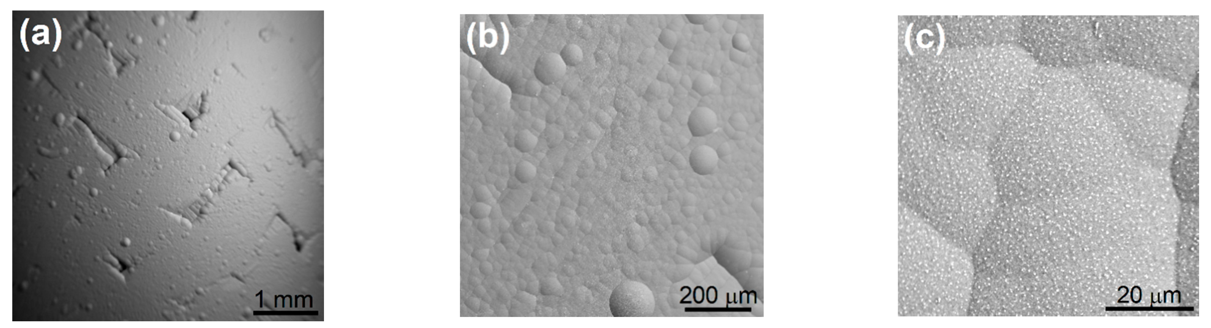
Figure 5.
SiCf/SiC sample: CVR SiC L2-16C roughness (Ra ~ 1–3 μm) after HT helium exposure at 900 °C, 90 m/s for 500 h (same zone, different magnification) (a–c).
Figure 5.
SiCf/SiC sample: CVR SiC L2-16C roughness (Ra ~ 1–3 μm) after HT helium exposure at 900 °C, 90 m/s for 500 h (same zone, different magnification) (a–c).

Figure 6.
(a) The depth distribution of implanted H+ ions and (b) the concentration profile of irradiation-induced vacancies ND,NRT calculated using the SRIM code [81] for the irradiation fluence of 1016 cm–2. The implantation profiles P+ of positrons emitted by 22Na radioisotope are plotted in the right panel by dashed lines.

Figure 7.
Back-scatter electron SEM micrographs of the alloys studied: (a) NbTaTi, (b) NbTaTiZr, (c) Nb0.5TaTiZr1.5, and (d) HfNbTaTiZr.
Figure 7.
Back-scatter electron SEM micrographs of the alloys studied: (a) NbTaTi, (b) NbTaTiZr, (c) Nb0.5TaTiZr1.5, and (d) HfNbTaTiZr.

Figure 8.
The development of the mean positron lifetime of NbTaTi, NbTaTiZr, Nb0.5TaTiZr1.5, and HfNbTaTiZr alloy with the irradiation fluence.
Figure 8.
The development of the mean positron lifetime of NbTaTi, NbTaTiZr, Nb0.5TaTiZr1.5, and HfNbTaTiZr alloy with the irradiation fluence.

Figure 9.
Results of decomposition of LT spectra: (a) the development of lifetimes τ1, τ2 of the exponential components resolved in LT spectra, and (b) intensity I2 of positrons trapped in irradiation-induced defects.
Figure 9.
Results of decomposition of LT spectra: (a) the development of lifetimes τ1, τ2 of the exponential components resolved in LT spectra, and (b) intensity I2 of positrons trapped in irradiation-induced defects.

Figure 10.
(a) The concentration of vacancies estimated from PAS data plotted as a function of fluence. (b) Comparison of the average vacancy concentration cNRT “seen” by positrons calculated by SRIM (dashed lines) and the real concentration of vacancies cV determined by PAS (solid lines).
Figure 10.
(a) The concentration of vacancies estimated from PAS data plotted as a function of fluence. (b) Comparison of the average vacancy concentration cNRT “seen” by positrons calculated by SRIM (dashed lines) and the real concentration of vacancies cV determined by PAS (solid lines).


Table 1.
Operating temperature ranges of nuclear reactor systems.
| Defined Temperature Ranges | Corresponding Reactor Systems |
|---|---|
| <300 °C | LWR, LFR, SCWR, GFR, MSR, V/HTR |
| 300–500 °C | LFR, SCWR, GFR, MSR, V/HTR |
| 500–1000 °C | GFR, MSR, V/HTR |
| >1000 °C | none |
| List of abbreviations: LWR—Light Water Reactor LFR—Lead colled Water Reactor SCWR—Supercritical Water cooled Reactor GFR—Gas cooled Fast Reactor MSR—Molten Salt Reactor V/HTR—Very/High Temperature Reactor | |
Table 2.
Overview of the GFR concepts.
| Reactor | GA GFR | GBR-2 | GBR-3 | GBR-4 | ENEA | Karlsruhe | UKEA | Gulf Ga | German GFR RD Program | USSR |
|---|---|---|---|---|---|---|---|---|---|---|
| Coolant | He | He | CO2 | He | He | He | He | He | He | N204 |
| Thermal power [MW] | 835 | 3000 | 3000 | 3450 | 1000 | 1000 | 1000 | 450 | 1000 | |
| Fuel type | pins | particle | particle | pins | pins | pins | pated particles | pins | pins | pins |
| Fuel material | UpuO2 | UpuO2 | UpuO2 | UpuO2 | UpuO2 | UPuC | UpuO2 | UpuO2 | UpuO2 | UpuO2&Cr coating particles in the pin |
| Clad Material | SS | SS | SS | SS | SS316 | SS316 | SS316 | SS | V-3Ti-1Si | 09X16H15M3B |
| Tcore,in [°C] | 323 | 260 | 260 | 260 | ||||||
| Tcore,out [°C] | 550 | 700 | 650 | 560 | 640 | 587 | 700 | 700 | 677 | |
| Pressure [MPa] | 8.50 | 12.00 | 6.00 | 12.00 | 7 | 12 | 5.2 | 6.8 | 16-25 | |
| Structural material | 12R72HV | |||||||||
| direct cycle turbine; need O2 getter for clad | UO2CrO3, UO2NNb2O5 new clad compatible with N2O4 | |||||||||
| Year of design data | 1974 | 1972 | 1972 | 1974 | 1968 | 1968 | 1968 | 1964 | 1970 | 1970 |
| Reactor | UK-ETGBR | Japan | ETDR | GFR600 | GFR600 | GFR2400 | JAEA GFR | Allegro | PB-GFR US | EM2 |
| Coolant | CO2 | He | He | He | He/sCO2 | He | He | He | He | He |
| Thermal power [MW] | 1200 | 2400 | 50 | 600 | 600 | 2400 | 2400 | 2400 | 300 | 500 |
| Fuel type | pins | kernels in SiC block | pin | pin | pin | pin | pin | pebble | pin | |
| Fuel material | UN | UPuO2 | UPuC | UPuC | UPuC | UpuN | UpuO2 | mixed U-TRU carbide | UC | |
| Clad Material | 20/25TiN | TiN, SiC, ZrC | AlM1 | SiC | SiC | SiC | SiC | MOX/SiC | SiC, ZrC | SiC/SiC |
| Tcore,in [°C] | 252 | 250 | 480 | 400 | 480 | 480 | ||||
| Tcore,out [°C] | 525 | 525 | 850 | 625 | 850 | 850 | 850 | 850 | ||
| Pressure [MPa] | 5.7 | 7 | 7 | 7 | 7 | 7 | 7 | |||
| Structural material | ref. AlM1 | Zr3Si2 | Zr3Si2 | Zr3Si2 | SiC | Zr3Si2, ref. SS316 | SiC/SiC, Zr3Si2 | |||
| direct cycle | for LWR spent fuel | a direct closed-cycle gas turbine power conversion with an organic Rankine bottoming cycle | ||||||||
| Year of design data | 1970 | 2002 | 2008 |
Table 3.
List of materials envisioned for use in the Prometheus program.
| Component | Material Option | Operating Condition | Development Concern |
|---|---|---|---|
| Fuel | UO2 | 900–1773 K ~1022 n/cm2 | Swelling/cracking at low fluence/burn-up/burn-up rate, fission gas release rate uncertainty |
| UN | Fission product chemistry, fission gas release rate, porosity evolution | ||
| Fuel Cladding | Nb-1Zr | 900–1300 K ~1022 n/cm2 | Creep capability, radiation-induced and interstitial embrittlement |
| FS-85 | Phase stability, radiation-induced and interstitial embrittlement | ||
| T-111 | Phase stability, radiation-induced, and interstitial embrittlement | ||
| Ta-10W | Radiation-induced and interstitial embrittlement | ||
| ASTAR-811C | Interstitial embrittlement, phase ftability, fabricability | ||
| Mo TZM | Irradiation embrittlement, irradiation creep capability, fabricability | ||
| Mo-47Re | Radiation-induced embrittlement, phase instability | ||
| SiC/SiC | Hermeticity, fracture toughness, conductive compliant layer | ||
| Liner | Re, W, or W-Re | 900–1500 K ~1022 n/cm2 | Embrittlement, hermeticity, reaction with fuel/cladding, neutron poison |
| None | FP attack of cladding | ||
| Fuel Spring | W-25Re | 800–1300 K ~1022 n/cm2 | Radiation-induced embrittlement, relaxation |
| Ta alloys | Radiation-induced and interstitial embrittlement, relaxation | ||
| In-Pin Axial Reflector | BeO | 900–1300 K ~1022 n/cm2 | Irradiation swelling, He gas release, 6Li neutron poisoning, BeO handling concerns |
| Core Block | Refractory Metal | 900–1200 K ~1022 n/cm2 | Fabricability, neutron absorption |
| Graphite | Fracture toughness, C transport to refractory metal fuel | ||
| Nickel Superalloy | Irradiation damage, C/O transport to refractory metal fuel | ||
| In-Core Structure | Refractory Alloys | 900–1200 K ~1022 n/cm2 | Fabricability, radiation-induced and interstitial embrittlement |
| Reactor Vessel | Nimonic PE-16 | Up to 900 K 1021 n/cm2 | Radiation-induced embrittlement, creep capability |
| Alloy 617 | |||
| Haynes 230 | |||
| Safety Rod Thimble (if used) | Same as Vessel | Up to 1050 K 1022 n/cm2 | Irradiation embrittlement, creep capability |
| Refractory metal | Irradiation embrittlement, creep, dissimilar material joining | ||
| Radial Reflector | BeO | Up to 900 K 1021 n/cm2 | Irradiation swelling and He gas release, 6Li poisoning, Be/BeO handling restrictions |
| Be | |||
| Shielding | Water | Up to 500 K | Thermal management |
| Be | Up to 800 K | Be handling restrictions during manufacturing | |
| B4C | |||
| LiH | Neutron and gamma swelling vs. temp. and irradiation | ||
| Shielding and Reflector Canning | Steel or Ni Super-alloy | Same range as shielding | |
| Titanium Alloy | |||
| Loop Piping | Alloy 617 | 300–900 K | Maintenance of internal insulation @ 900 K, Joining |
| Haynes 230 | Maintenance of internal insulation @ 900 K, Joining | ||
| Insulation | Porous Metal or ceramic | Up to 1150 K | Thermal conductivity, loop material compatibility |
| Ceramic Fiber | Thermal conductivity, loop material compatibility | ||
| Insulation Liner | Mo Alloy | Up to 1150 K | Fabricability, compatibility with insulation, embrittlement |
| Superalloy | cmpatibility with insulation | ||
| Turbine Casing (scroll) | In-792 | Up to 1150 K | Creep capability, dissimilar materials joining (to piping) |
| Mar-M-247 | |||
| Alloy 617 or Haynes 230 | Up to 900 K | Requires internal insulation | |
| Turbine Wheel | In-792 | Up to 950 K | Creep capability, carburization/decarburization/deoxidation |
| Mar-M-247 | |||
| Compressor | Ti-Al-V | 400–600 K | Compatibility w/gas loop |
| Superalloy | |||
| Shaft | 1018 Steel | 400–900 K | |
| Superalloy | |||
| Alternator Magnets | Sm-Co | 400–450 K | Loss of magnet strength, compatibility with gas loop |
| Electrical Insulators | Ceramic or Glass | 400–450 K | Hermeticity, compatibility with gas loop |
| Recuperator Core | Alloy 625/690 | 600–900 K | Thermal stability at hot side temp, Braze material concerns |
| Carbon/Carbon | Compatibility with other loop components (C transport), fabricability | ||
| Cooler Core | CP Titanium | 400–500 K | Compatibility with gas and water loops |
| Alloy 625/690 |
Table 4.
List of refractory metal alloys studied in the present work. The table shows the composition of each alloy, atom misfit parameter (δ) representing a measure of the magnitude of lattice distortions, configurational entropy of a random solid solution (SSS), results of a tensile test with a constant strain rate of 2 × 10⁻⁴ s–1 [80]: yield strength (YS), ultimate tensile strength (UTS), and elongation-to-failure (Amax). Vickers hardness (HV) measured using a load of 0.5 kg applied for 10 s, and the average cross-section for absorption of epithermal neutrons (σ).
| Composition | δ (%) | SSS (R) | YS (MPa) | UTS (MPa) | Amax (%) | HV (GPa) | σ (barn) |
|---|---|---|---|---|---|---|---|
| NbTaTi | 1.05 | 1.10 | 620 | 683 | 18.5 | 2.42 ± 0.02 | 9.3 |
| NbTaTiZr | 4.83 | 1.39 | 1144 | 1205 | 6.4 | 3.64 ± 0.02 | 7.0 |
| Nb0.5TaTiZr1.5 | 5.22 | 1.32 | – | 843 | 0 | 4.80 ±0.03 | 6.9 |
| HfNbTaTiZr | 4.98 | 1.61 | 1155 | 1212 | 12.3 | 3.48 ± 0.03 | 23.3 |
Publisher’s Note: MDPI stays neutral with regard to jurisdictional claims in published maps and institutional affiliations. |
© 2021 by the authors. Licensee MDPI, Basel, Switzerland. This article is an open access article distributed under the terms and conditions of the Creative Commons Attribution (CC BY) license (http://creativecommons.org/licenses/by/4.0/).
Share and Cite
MDPI and ACS Style
Čížek, J.; Kalivodová, J.; Janeček, M.; Stráský, J.; Srba, O.; Macková, A. Advanced Structural Materials for Gas-Cooled Fast Reactors—A Review. Metals 2021, 11, 76. https://doi.org/10.3390/met11010076
AMA Style
Čížek J, Kalivodová J, Janeček M, Stráský J, Srba O, Macková A. Advanced Structural Materials for Gas-Cooled Fast Reactors—A Review. Metals. 2021; 11(1):76. https://doi.org/10.3390/met11010076
Chicago/Turabian StyleČížek, Jakub, Jana Kalivodová, Miloš Janeček, Josef Stráský, Ondřej Srba, and Anna Macková. 2021. "Advanced Structural Materials for Gas-Cooled Fast Reactors—A Review" Metals 11, no. 1: 76. https://doi.org/10.3390/met11010076
Note that from the first issue of 2016, this journal uses article numbers instead of page numbers. See further details here.