


Abstract
We reported a simple and compact Yb-doped fiber femtosecond oscillator, which is based on a dispersion management and nonlinear polarization evolution (NPE) technique. Here, 84 fs, 4 nJ at 1030 nm pulses were generated directly from the mode-locked fiber oscillator by optimization of the net dispersion of the cavity. Only a pair of gratings was used to compensate the positive dispersion caused by the fibers and other optics in the cavity. This is, to our knowledge, the shortest pulse duration directly from a fiber oscillator without any extra compressor outside the cavity.
Export citation and abstract BibTeX RIS
Introduction
In recent years short pulse fiber oscillators have been widely used as seed lasers for most types of high-power laser system [1–3]. As an alternative to bulk solid-state oscillators, the fiber oscillator is more compact, more stable and free from misalignment. Moreover, the pulse energy of several nanojoules, or higher levels, from the fiber oscillator is no longer a problem [4–6].
Fiber oscillators usually produce chirped pulses with pulse durations of hundreds of femtoseconds, which need to be de-chirped by extra setups outside the cavity to transform limit the pulse duration. Many types of de-chirping techniques have been used in recent years, including the use of diffraction gratings [7], prisms [8], both diffraction gratings and prisms [9], different types of fibers with negative dispersion [10–12],optical fiber grating [13], and so on. Although many researchers have worked hard obtaining transform-limited pulses directly from fiber oscillators in the past, this is still tough work. Also, the shortest pulse durations obtained from the oscillator are all several times wider than the transform limit. The shortest pulse duration can be obtained by careful optimization of several parameters, including the interaction of positive and negative dispersion, the gain in the Yb-doped fiber, the nonlinearity effects level, as well as the matching methods among the wave plates in the cavity. Therefore, to obtain the shortest duration pulses from a fiber oscillator, the first thing one needs to understand is the effects of cavity dispersion, as we know that one can obtain the shortest pulse duration when the net dispersion of the cavity is close to zero [14]. For example, Lim achieved 120 fs from a fiber oscillator with a net dispersion of −0.021 ps2 [15], which was de-chirped to 75 fs by external gratings outside the cavity. Teamir and Ilday achieved 62 fs pulses directly from the oscillator with two pairs of diffraction gratings inside the cavity [16]. The extra gratings inside the cavity take up more space and make the oscillator size bigger. Although one can obtain tens of femtoseconds pulse wide pulses with the gratings outside the cavity, the output spectrum is bat-eared in shape. When the gratings are inside the cavity, the output spectrum is Gaussian shaped, which is suitable for the following amplification. This is the main purpose for building the fiber oscillator with the gratings inside the cavity in our laboratory.
Here, we reported a fiber oscillator with an output pulse duration of 84 fs and pulse energy of 4 nJ, which is based on the dispersion management and nonlinear polarization evolution (NPE) technique. We believe that these are the shortest pulses generated directly from a fiber oscillator with only a pair of diffraction gratings inside the cavity. In this paper we will discuss the effects of the net dispersion of the cavity, the gain of the Yb-doped fiber, the nonlinearity effect self-phase modulation (SPM), as well as different matching methods of the wave plates, which act as the spectrum filter in the cavity. Finally, the effect of third order dispersion (TOD) will also be mentioned and discussed. In the meantime, we will describe the building of this type of fiber oscillator. We also show some phenomena that could occur during the building of the oscillator, and then give the corresponding solutions.
Experimental setup
A schematic of the experimental setup is shown in figure 1. The oscillator includes an Yb-doped fiber (YDF) of length 850 mm (Nufern). The core and clad diameters of the YDF are 6 µm and 125 µm, respectively, and the absorption of the pump beam is 250 dB m−1 at 975 nm. Following the YDF is the part 1 single mode fiber (SMF). The other end of the YDF was spliced to a 68 cm long SMF (part 2) and part 3 SMF. Here, SMF parts 1 and 3 were considered as the variable parts to change the total length of the SMF. The mode-field and clad diameters of the SMFs are 6.2 µm and 125 µm, respectively. The splicing losses for each point were less than 0.02 dB. A fiber-coupled laser diode with an output wavelength of 980 nm and maximum power of 730 mW was used to pump the YDF. The pump beam was delivered through a 980/1060 nm wavelength division multiplexer (WDM) into the YDF. The quarter wave plates (QWP1 and QWP2), the half wave plate (HWP) and the polarizing beam splitter (PBS) in the cavity play the role of an artificial saturated absorber, realizing the passive mode-locked operation with nonlinear polarization rotation [17]. An optical isolator was used inside the cavity to make the oscillator operate at a unidirectional ring geometry. A pair of reflection-type gratings with a groove density of 600 l mm−1 that provide anomalous group velocity dispersion (GVD) were used to compensate the positive group delay dispersion (GDD) caused by the fibers and other optics. The net GDD of the cavity was controlled by carefully adjusting the distance between the gratings and the length of the SMFs (parts 1 and 3).
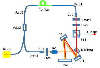
Figure 1. A schematic of the Yb-doped fiber oscillator. LD: laser diode; WDM: wavelength division multiplexer; CL 1, 2: collimated lens; QWP 1, 2: quarter wave plates 1 and 2; HWP: half wave plate; PBS: polarizing beam splitter cube; D-Mirror: D-shape mirror; G1, G2: grating 1 and 2; EM: end mirror; ISO: isolator.
Download figure:
Standard image High-resolution imageResults and discussion
Before showing the results, we would like to provide some information regarding how to obtain mode locking in this type of fiber oscillator. First, one should start from CW operation of the cavity. Under these circumstances, only the QWP1 and an isolator are needed in the cavity; we do not need the HWP and QWP2 at present. Once the cavity is well aligned, we need to adjust every free space optic, except for the gratings. When the reflected angle and the distance between the gratings are well calculated, we do not need to change it now. Only the distance could be slightly adjusted in the following steps to change the net dispersion of the cavity. In CW operation, the aim of adjusting the cavity is to make the CW lasing threshold as low as possible, including optimizing the beam alignment and the rotation of the QWP1. Then, we put in the HWP and QWP2 one by one, and obtain the maximum output power, respectively. The next step is to achieve mode locking, by rotating the wave plates. If we simply randomly rotate the three wave plates, this will be a considerable amount of work. Therefore, once the CW operation is well aligned, we can then obtain mode locking by rotating the HWP and QWP2. Now that the variable has become two from three, this will be easier. First, we may rotate the QWP2 roughly for half a round; if there is no mode locking, then we rotate the HWP slightly (one degree per step or less), then go back to rotating the QWP 2 roughly. By simply repeating the steps of rotating the QWP 2 and HWP, one may obtain mode locking in a short time.
To obtain the shortest pulse duration directly from the fiber oscillator, it is first necessary to understand the dispersion regime in the fiber oscillator. The fibers (including SMF and YDF) and other elements provide positive GVD at 1030 nm, which is compensated by the gratings with negative GVD. As the net GDD is close to zero, shorter pulses will be obtained [14]. In this paper, the net GDD of the cavity was controlled by changing the length of the SMFs (part 1 and part 3) and the distance between the gratings. The net dispersion of the cavity was calculated based on the sum of the components in the cavity, including the SMFs, YDF, wave plates, PBS, the gratings and the YIG (yttrium-iron garnet) crystal in the isolator. In our experiment, the SMFs are from the parts of the WDM and collimators; we may get the GVD of the SMFs from the manufacturers. The GVD of the SMF is about 22.6 fs2 mm−1 at 1060 nm, and the GVD of the YDF is about 24 fs2 mm−1. But the GVD values of the fibers could be different from the manufacturing features, or from each batch of fibers. At the same time, when the pump power is increasing, the SPM effect will be stronger; then, the corresponding positive dispersion will be increased. From this perspective, the GVD of the fiber is increased. Therefore, the calculated results are not the precise results, which are just good for estimating the dispersion of the cavity. All of the wave plates in the cavity are zero order and made from quartz, and the total GDD of the wave plates is about 22.8 fs2 at 1030 nm. The PBS we used is from Thorlabs, which is made from SCHOTT-SF, and the GDD of the PBS is 1250 fs2 at 1030 nm. Compared with the fiber parts and the gratings, the dispersion caused by other free space components in the cavity is quite small. Therefore, we only consider the dispersion between the fiber parts and the gratings. Once the lengths of the fibers are fixed, the net dispersion of the cavity will be carefully optimized by changing the distance of the gratings.
The dispersion parameters of a grating pair compressor for a given distance between gratings L, angle of incidence  and groove density
  . Formulas for the double-pass GDD and TOD are, respectively [18]:
The total SMF length was changed from 4.38 m to 2.68 m, and the distance of the gratings was changed from 50 mm to 63 mm. All the results for different cases (I–IV) are shown in table 1.
Table 1. All the results with different SMF lengths and different distance L between the gratings.
| SMF (m) | L (mm) | Mode-Locking state | Net GDD (ps2) | Ppump (mW) | Δλ (nm) | Δτ (fs) | |
|---|---|---|---|---|---|---|---|
| I | 4.38 | 50 | NO | 0.05 | 730 | 6.46 | —— |
| II | 3.66 | 50 | NO | 0.03 | 730 | 6.15 | —— |
| III | 2.68 | 60 | YES | −0.004 | 730 | 49.6 | 113 |
| IV | 2.68 | 60 | YES | −0.004 | 310 | 34 | 123 |
| V | 2.68 | 63 | YES | −0.008 | 730 | 49.6 | 84 |
At the beginning, we built the oscillator with a total SMF length of nearly 4.38 m (SMF: 1.1 m of part 1, 0.68 m of part 2, 2.6 m of part 3); the total GDD from the fiber parts is about 0.12 ps2. The distance between the gratings was 50 mm, according to the formulas (1) and (2), and the corresponding GDD of the gratings is −0.07 ps2. The net dispersion of the cavity is about 0.05 ps2. This is case I shown in table 1. The maximum pump power we used was 730 mW at 976 nm, and the repetition rate was 24.4 MHz. During the process of adjusting the mode locking, we found that no matter how we adjusted all of the wave plates and pump power, the output waveform on the oscilloscope was always unstable or just Q-switching mode locking. The output pulse waveforms are shown in figures 2(a) and (b). The measured spectrum bandwidth of the output pulses was about 6.46 nm, which is shown in figure 2(c). This is quite narrower than those reported in other papers [7, 8, 15]. Also, this narrow bandwidth and huge positive net dispersion are more likely to be caused by the short distance between the gratings and the long length of the SMFs. Therefore, to improve the oscillator, we shortened the length of the SMF first. After rough calculation of the dispersion, we shortened the SMF length of part 3, which is connected with the WDM, to 1.88 m from 2.6 m, and kept the distance of the gratings the same as in the first case (50 mm); the repetition rate was increased to 36.8 MHz. This is case II shown in table 1. The net dispersion of the cavity is about 0.03 ps2. Then, we found that the operational state of the oscillator was the same as the previous case; the output pulse waveform shown on the oscilloscope was not stable, regardless of wave plate matching with different angles. The measured spectrum of the output pulse and the bandwidth were similar to case I. For both cases, the positive net dispersion is quite huge and far from zero. This is perhaps the main reason for the unstable mode locking or Q-switching mode locking.

Figure 2. (a) The output pulse waveform with a repetition rate of 24.4 MHz; (b) the Q-switching mode locking from the oscillator; (c) the spectrum of the output pulse in the unstable state.
Download figure:
Standard image High-resolution imageThen, we cut the SMF (SMF of part 1) to a shorter length of 12 cm, and at the same time, we increased the distance of the gratings to 60 mm. This is case III shown in table 1. The net dispersion of the cavity was negative with a value of about −0.004 ps2. At last we obtained stable mode locking, and the repetition rate was 49.7 MHz. The output pulse waveform and spectrum with a bandwidth of 49.6 nm are depicted in figure 3(a). We measured the pulse autocorrelation trace using the autocorrelator (PulseCheck A.P.E.). The pulse width was 113 fs with sech2 fitting at a pump power of 730 mW directly from the oscillator; the pulse width is depicted in figure 3(b). In this case, the stable mode locking operation can be obtained at a wide range of pumping power from 310 mW to 730 mW, and the maximum output power was 220 mW at 1030 nm; the single pulse energy was equivalent to >4 nJ. In the present setup, no matter how we changed the matching methods of the wave plates, mode locking was always easy to obtain.
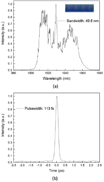
Figure 3. (a) The spectrum and waveform of the output pulses from the oscillator in case III; (b) the output pulse duration at a pump power of 730 mW.
Download figure:
Standard image High-resolution imageWith the exception of the net dispersion, we studied the effects of the gain on the pulse width. Then, we found that the output pulse durations at high and low pump power were different. The higher the pump power, the shorter the pulse width. The main reason for this is the SPM at high pump power; the measured spectrum bandwidths of 49.6 nm and 34 nm (case IV in table 1) at pump powers of 730 mW and 310 mW, which are shown in figure 4. The corresponding pulse widths are 113 fs and 123 fs, respectively. Thus, we can see that with the gain of the YDF increased, the SPM effect is growing, and the output spectrum is wider. At last, the short pulse duration pulses are obtained. At the same time, compared with the cases of the oscillator, we speculate that when the net dispersion of the cavity is negative, stable mode locking is easy to obtain. Apart from this, the high repetition rate has also somehow contributed to the stability; as the intra-cavity pulse travels along a shorter fiber and suffers less from 'environmental noise', such as temperature variation and mechanical vibration, which may disturb and even destroy the mode locking [19].

Figure 4. The spectrum bandwidths at 310 mW and 730 mW.
Download figure:
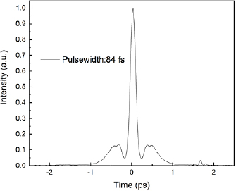
Standard image High-resolution imageTo obtain a shorter pulse width, we slightly adjusted the distance between the gratings. When we moved the second grating a slightly longer distance from the first one, we found that the pulse width, which was measured on the autocorrelator, became shorter to 84 fs with sech2 fitting. The corresponding distance between the gratings was 63 mm. When we increased the distance further, the pulse width was increased. Therefore, the 84 fs output pulse width was the shortest that we could achieve directly from the present oscillator, and the corresponding net dispersion of the cavity was about -0.008 ps2. The pulse duration is shown in figure 5. However, small peaks at each side of the main peak can be observed. This is caused by the accumulation of TOD, which is from the fibers and gratings; when the distance of the gratings increased, the corresponding positive TOD accumulated further. In some reports [7, 20–22], the authors speculated that the TOD could be compensated by the SPM effects, which are most likely caused by the nonlinear phase shift (NPS) in fibers. But in our experiments the pump power may not be high enough to bring strong SPM effects to compensate the TOD completely. This is just speculation from other researchers' results; we have not confirmed this inference in our study. Compared with case III, the output pulse width is shorter, but with bigger net dispersion. The same phenomenon can be found in the report from Lim [15]. We can see that as a rule the shortest pulse can be obtained when the net dispersion is zero, which is not suitable for the chirped pulse directly from the oscillator. But it is certain that the shortest de-chirped pulse will be obtained in the third case with extra de-chirped devices outside the cavity.
Figure 5. The shortest pulse duration from the oscillator.
Download figure:
Standard image High-resolution image
Conclusion
In conclusion, we have built an Yb-doped fiber oscillator with one pair of gratings inside the cavity with an output pulse width of 84 fs, 4 nJ by optimizing the net dispersion of the cavity. While studying this type of oscillator we summarized some key points for building this type of laser. First, stable mode locking is easy to achieve at a negative net dispersion of the cavity from our experience. We can also judge whether the mode locking is normal or not by checking the spectrum bandwidth of the output pulses. It is normal with a bandwidth of more than 20 nm (around 6 nm in our first case is not normal). Second, the shortest pulse width obtained directly from the oscillator does not depend on the rule that the shortest pulses will be obtained when the net dispersion approaches zero. At the same time, the SPM contributes to the narrowing pulse width. Third, there are small peaks at each side of the main peak, which are caused by the TOD accumulated from the fibers and the gratings. If the SPM is strong enough, the TOD effects could be compensated completely. Fourth, sometimes the double-pulse phenomenon appears. By slightly adjusting the QWP1 or changing the pump power one can make the laser operate properly again. The oscillator we have built is compact and robust, and can serve as a seed source for the following high power and high energy amplifiers.
Acknowledgments
The authors thank their colleagues for discussion and for providing optics during the experiments. This result was co-financed by the European Regional Development Fund and the state budget of the Czech Republic (project HiLASE CoE: Grant No. CZ.02.1.01/0.0/0.0/15_006/0000674) and by the European Union's Horizon 2020 research and innovation programme under grant agreement No. 739573. This work was also supported by the Ministry of Education, Youth and Sports of the Czech Republic (Programmes NPU I Project No. LO1602, and Large Research Infrastructure Project No. LM2015086).