
Abstract
Considerable progress has been made over the last decades in thermal spray technologies, practices and applications. However, like other technologies, they have to continuously evolve to meet new problems and market requirements. This article aims to identify the current challenges limiting the evolution of these technologies and to propose research directions and priorities to meet these challenges. It was prepared on the basis of a collection of short articles written by experts in thermal spray who were asked to present a snapshot of the current state of their specific field, give their views on current challenges faced by the field and provide some guidance as to the R&D required to meet these challenges. The article is divided in three sections that deal with the emerging thermal spray processes, coating properties and function, and biomedical, electronic, aerospace and energy generation applications.
Introduction
Thermal spray is now regarded as a key and environmentally friendly technology to design and modify the properties of surfaces and characteristics of components. It is commonly used in many industrial sectors including transport, energy, materials extraction and processing, biomedical and electronic applications (Ref 1). The global market (revenue generated through material, equipment and coating manufacturing) was estimated at USD 7.58 billion in 2015 and is expected to grow at a compound annual growth rate of 7.79% to reach USD 11.89 billion by 2021 (Ref 2). Market drivers include the rising demand for electricity production, air transport, automotive manufacturing and economic development.
Thermal spray is being developed continuously to meet the challenges raised by the global market evolution and pressures put by the price competition, product and materials regulations and environmental, health and safety requirements. However, these challenges often come along with opportunities, e.g., environmental concerns about chrome electroplating hexavalent chromium have brought about the replacement of hard chrome coatings by the “greener” thermal spray coatings.
Industry is responding to these challenges in a number of ways. They include the traditional concerns of industry (e.g., cost reduction, quality and reliability improvement, productivity and profitability increase with lean manufacturing approaches) and more risky approaches (e.g., development of new thermal spray coating processes, innovative plasma torch designs, new coating materials). However, the science often lags behind these developments, and technological issues may slow down or even stop them. Many universities and research institutes, worldwide, are attempting to better understand the science behind thermal spray and use it to address these issues. This article aims to identify the challenges posed by current market needs and propose research directions and priorities to meet these challenges. The formative idea is to develop a Thermal Spray Roadmap by surveying well-known experts in academia, research institutions and industry and soliciting their ideas on (i) the scientific and technology issues facing existing and emerging spray processes, coating materials and applications and (ii) the advances necessary to address these issues. A similar approach was followed by the plasma community in 2012 and resulted to the Plasma Road Map (Ref 3).
The 2016 Thermal Spray Roadmap was built on the individual vision of the authors who responded to the request of the editors of Journal of Thermal Spray Technology. It does not claim to present a comprehensive picture of the status of the interdisciplinary and complex thermal spray domain; for example, environmental barrier coatings, automotive applications, process on line control are not tackled in this review despite their growing importance. Nevertheless, we believe that the ideas expressed in this roadmap reflect the current activity of the thermal spray community and we hope they will provide useful guidance regarding current and emerging issues that offer opportunities for R&D investment for developing improved products, in terms of quality and performance at a lower life cycle cost.
This review is divided into three sections. The first identifies the challenges faced by existing and emerging spray processes and suggestions for meeting these challenges. The second deals with traditional functions of spray coatings (resistance to wear and corrosion) and more recent applications; the last section is an overview of the issues ahead and of possible approaches to address them for biomedical, electronic, aircraft propulsion and energy generation applications.
Thermal Spray Processes
Cold Spray: Coatings and Additive Manufacturing
Bertrand Jodoin, Franck Gärtner, and Eric Irissou
Current State of the Field
Cold gas dynamic spraying (also termed cold spray or Kinetic Spray) is the latest spray technique of the thermal spray (TS) processes family (that include plasma spraying and HVOF spraying). In cold spray (CS), compressed inert gases (typically nitrogen and helium) accelerate powder particles (typically metallic particles with diameters ranging between 10 and 100 μm) in a De Laval nozzle to supersonic speeds (up to 1000 m/s) prior to impact onto the substrate (Ref 4). Process gas heating to temperature of up to 1000°C is applied to reach a higher velocity of sound of the gas passing the nozzle throat and thus higher particle velocities. Figure 1 illustrates schematically a CS setup. The spray particles are injected inside the nozzle to be directed toward the substrate to be coated. Upon impact with the substrate, the particles plastically deform resulting in a material flow directing outwards the contact zone disrupting the thin surface oxide films (cleaning effect). The particle and substrate interfaces are locally heated under the high strain rates causing thermal softening of the material to thresholds over compensating strain hardening and strain rate hardening, thus resulting in adiabatic shear instabilities (Ref 5, 6). This results in intimate conformal contact between the exposed metal surfaces allowing mechanical and metallurgical bonding to occur, leading to the formation of a coating (Ref 6). Figure 2 presents examples of CS TiAlV64 particles after impact on a titanium substrate, demonstrating the high degree of local deformation and metallurgical bonding at interfaces of a removed particle.

Schematic of cold spray equipment setup

Single impacts of cold-sprayed TiAlV 6 4 particles on titanium, showing (left) a cross section, (middle) particle flattening and jets under perspective view, and (right) a particle that was removed from the substrate. Example demonstrates that metallurgical bonding by ASI occurs in the particle substrate interfaces, providing higher strength as compared to the substrate material
Deposition efficiencies can reach over 90%, with the resulting coatings showing very low porosity levels. Process gas temperatures are usually kept in a range that the sprayed particles are never exposed to temperatures close to their melting point. Consequently, the process is referred to as a solid-state process (Ref 6). As such, it is possible to spray temperature sensitive materials such as titanium (and alloys), copper (and alloys), aluminum (and alloys), nanocrystalline materials and metallic glasses without affecting the powder feedstock phase content and without oxide contamination (Ref 4, 7). CS coatings usually present compressive residual stresses, allowing building thick coatings/layers. As such, CS can be used not only to build coatings but also to repair/rebuild/refurbish parts as an additive manufacturing process (Ref 8). Cold spray repairs have been so far mainly aimed at dimensional restoration while providing corrosion/oxidation/wear protection. The metal powder sprayed for part restoration may or may not be the same metal as the part being restored.
CS is a green/environmentally friendly technology as it does not involve combustible fuels or gases. As a low-temperature process, it consumes limited energy, and the over sprayed expensive raw material can potentially be recycled. Commercial systems are available in both portable and stationary production versions. As such, the portable (hand held gun) system is a versatile tool that is suitable for front line, allowing in situ repairs with minimal surface preparation. Due to its nature, the process allows localized repairs, usually without or very limited masking and without bond coats and flashing (Ref 8).
Many materials have been successfully sprayed by CS including Al, Cu, Ni, Ti, Ag, Zn, Ta, Nb and their alloys as well as composites such as Cu-W, Al-SiC, Al-Al2O3 to name a few (Ref 8). CS is currently being used in the military, aerospace and energy industries.
Current Challenges
Among the challenges that CS faces, a major one is market penetration and diversification. Although many applications have been tailored for military, aerospace and energy industries, CS still lacks a “mass market” penetration as reached by plasma spray and HVOF spray processes and has yet to attract interest in other areas. This can be attributed to the lack of exposure to general markets that present strong potential for CS. Few job shops have CS systems operational and available, but time is required to get new specifications targeted for CS coatings. Particularly, repair approval cycles can take some times and are costly. As such, it is critical to engage industry on a continuing basis to communicate and educate potential users non-familiar with metal spraying about advantages, challenges and ultimately successes with CS.
CS is facing technical challenge the fact that there are only a few commercially available powders that are specifically designed for this process. As such, the vast majority of coatings and repairs produced by CS are not using optimal feedstock powders (Ref 8). Current efforts aim for process and feedstock specifications to ensure enhanced performance by tailored feedstock powders with respect to phase contents and purity, both influencing the needed deformability. Specifications also aim for tuning powder size distributions, as smaller and larger particles may not be able to impact on the substrate with sufficient velocity to induce plastic deformation and bonding.
Over the last few years, CS has been seen as a potential additive manufacturing (AM) process that could complement powder bed AM processes. Simple AM parts have been produced by cold spray, but the ones reported have been limited to small sizes (Ref 9). The transition of CS use beyond coatings and dimensional restorations into complex additive manufacturing applications presents several technical challenges as CS faces a number of commercial barriers as other AM methods. The major advantages of CS as an AM process compared to laser-based processes are mainly the minimal heat input of the process and the substantially larger deposition rates that can be achieved. These advantages potentially allow the process to be used without the requirement of an inert environment. With respect to the use of post-processing heat treatments, needed efforts could be similar to those for laser AM.
Advances in Science and Technology to Meet the Challenges
Within the last two decades, CS has developed from a laboratory deposition technique to a reliable process for applications that demand a high coating purity and the preservation of unique feedstock properties. Figure 3 shows the layout of a central processing unit (CPU) cooling unit processed by CS (Ref 15). Various manufacturers offer a range of CS equipment, each presenting their own benefits and having their potential niche market and with some successful commercial applications, either as a coating or as a repair/refurbishing process.

Layout for heat sinks as first commercial application in cold spray established in 2003. (a) Layer layout in cross section, (b) assembly of heat sink and cold-sprayed coating and finally soldered plate for heat distribution, (c) the verax P16Cu fan for CPU cooling
However, tailoring of existing feedstock powder production methods or the development of new innovative processes to manufacture feedstock powders adapted to CS is of utmost importance for the technology to be able to expand further (Ref 10). As such, to be able to develop new markets for CS and strengthen the existing ones, it becomes crucial to have material manufacturers getting involved more closely with the CS community and potential end users to establish strategic partnerships to exchange information/requirement/specification that would lead to enhanced feedstock design tailored for applications. With respect to so far conventional spray materials, CS will increase its share in repair, but will have new markets by new solutions in production technologies as well as in additive manufacturing.
The potential for CS to occupy a niche as an additive manufacturing process is undeniable, but it is in its early stage. In the design stage, AM build methodologies should be adapted to the specifics of CS (e.g., characteristic spot resolution and profile associated with nozzle geometry and gas particle flow dynamics) using tools such as process modeling, build strategy development (Ref 11) and tool path programming with computer-aided design/computer-aided manufacturing (CAD/CAM). Although advances at the raw material level (e.g., feedstock optimization and/or tailored powders) as well as in equipment development [e.g., laser assisted spray, in situ machining and diagnostics (Ref 11, 12)] allow a wide range of materials to be sprayed (Ref 13), obtaining bulk equivalent material properties remains a challenge and appropriate post-processing operations must be developed (Ref 14). Additional development in areas of non-destructive testing (NDT), automation and process control, as well as ensuring proper implementation of applicable environment, health, and safety (EH&S) measures, is also required to grow from low volume to mass production. From an engineering perspective, the uncertainty in whether AM builds perform similarly to conventional parts requires rigorous qualification procedures and acceptance criteria to be developed.
To discover the full potential of CS, recent efforts involve interdisciplinary approaches involving basic materials science and production technology. In new material developments, functional properties are very well tuned to applications. So far, only a couple of techniques such as CS, minimizing the heat input, can preserve or guarantee the desired materials behavior. The chance to preserve functional powder properties in coatings or massive parts is promising a completely new range of developments and markets.
Aerosol Deposition Method
Jun Akedo and Kentaro Shinoda
Current State of the Field
Lately, the aerosol deposition (AD) method has attracted attention as a fabrication technique for depositing ceramic coatings at room temperature. The AD method offers a unique approach for depositing ceramic coatings and involves the acceleration of solid-state submicron ceramic particles (both oxides and non-oxides) in a gas flow to a few hundred meters per second to impact with the substrate under vacuum. This procedure leads to the rapid formation of a dense, uniform and hard ceramic layer at room temperature without the need for additional heating to melt the particles of the starting powder, as shown in Fig. 4. The discovery of this phenomenon resulted in the birth of the AD method, and the phenomenon of depositing solid-state particles in this manner became known as room-temperature impact consolidation (RTIC) (Ref 15, 16). The AD method is expected to not only reduce the energy consumption and cost, but also the difficulties associated with fabricating thin films or thick coatings using materials with complicated compositions, and the number of processes required to manufacture electronic devices. In addition, the method has led to a substantial improvement in the performance of these materials.

Cross-sectional images of Al2O3 powder particles and an AD coating observed by transmission electron microscopy (Ref 16)
In 2007, TOTO commercialized a coating technology based on the AD method for semiconductor fabrication equipment. This coating technology, which employs Y2O3 coatings with a hardness on par with that of sapphire and produces coatings that are highly resistant to plasma erosion, has become indispensable for next-generation semiconductor fabrication equipment and improves chip yields dramatically (Ref 17).
Classification of AD Method in Spray Coating Technologies
The AD method specified in this section is a process for the fabrication of ceramic coatings, which are produced by spraying fine solid powder particles under vacuum, by utilizing RTIC. This deposition mechanism is different from conventional thermal spray processes based on the melting and solidification of impacting particles (Fig. 5). Similar processes are known so-called vacuum cold spray or vacuum Kinetic Spray (Ref 18-20). They can also be considered to be classified as AD methods here in terms of the deposition mechanism (Ref 21).

Comparison of AD method to other spray coating processes based on collision of solid-state particles (Ref 16)
The cold spray (CS) deposition method is well known in the research field of thermal spray technology (Ref 22). This method involves the acceleration of large sized particles with a diameter exceeding 10 µm by a hot carrier gas heated to 300-1000°C and sprayed onto a substrate at atmospheric pressure by using an ultrasonic nozzle known as a Laval nozzle. The CS method is very similar to the AD method in terms of utilizing kinetic energy, but the production of ceramic coatings by this method has not been successful to date.
Apparatus and Procedure of AD Method
The AD method entails spraying fine powder particles onto a substrate under vacuum. The principle of this method is rather simple; hence, the apparatus required for AD is also not so complex. In general, the AD system consists of an aerosol generator, a deposition chamber with a spray nozzle and a substrate holder, an evacuation system and process diagnostic tools if needed. The AD system only requires low vacuum levels; thus, a rotary vacuum pump coupled to a mechanical booster pump suffices to evacuate the chamber to a pressure of about 10 Pa-1 kPa during deposition. The apparatus is easy to scale up because of the simple principle on which it is based and the low vacuum conditions.
Powder particles are mixed with a gas to generate an aerosol. This aerosol is ejected through a nozzle at low pressure and impacted onto a substrate. Sintered, ceramic powders with a particle size range of about 0.08-2 µm are typically used as the deposition particles. After suspension in the carrier gas to form an aerosol, the aerosol is accelerated to several hundreds of meters per second through an orifice with a width less than 1 mm. The formation of layers of an acceptable density and with the desired material properties requires the preferential use of particles with a particular size and morphology (Ref 16).
Current Challenges
Figure 6 shows a roadmap of the AD method. Applications of the AD method in microdevices, such as microactuators, RF-embedded passive components, high-speed optical modulators, were largely developed during the “Nano Structure Forming for Advanced Ceramic Integration Technology Project” as part of the Japan Nano Technology Program in 2002-2007. These microelectronic device applications were reported elsewhere (Ref 17). The most notable feature of the AD method is that because the process is proceeded at room temperature, almost all kinds of materials can be used as raw powders (films) and substrates including ceramics, metals, polymers, bulk metallic glasses (BMG) and composites with various coating structures, such as single, multi- and gradient layer (Ref 23-26), which are also good candidates for manufacturing energy-related devices such as dye-sensitized solar cells, all solid-state Li-ion batteries (LIB), solid oxide fuel cells (SOFCs), thermoelectric generators and heat dissipation circuit board for high power electric modules (Ref 21). Medical applications such as ceramic coatings for dentures and artificial bones have also been studied (Ref 27) (Fig. 7).

Application load map of AD method

Schematic of hybrid aerosol deposition
The deposition conditions of the AD method greatly depend on the properties of the raw materials and starting powder and leave many challenges and opportunities such as increasing the deposition efficiency, reducing the coating cost and obtaining improved coverage of the complicated surface of a three-dimensional object. Presently, the mechanism by which the collision of fine solid-state particles leads to deposition is yet to be elucidated. If the particle size is too large, erosion similar to that caused by grit blasting occurs; however, if the particles are too small, the particle inertia is insufficient to induce RTIC, leading to the formation of a pressed compact instead. Thus, a more detailed understanding of the RTIC process is required (Ref 25).
Advances in Science and Technology to Meet These Challenges
Technological Advances in Microstructure and Applicable Substrates. An AD layer is composed of high-density and randomly oriented polycrystalline nanostructures with a crystallite size less than 20 nm. Electron diffraction imaging in transmission electron microscopy revealed neither amorphous layers nor hetero-structures at the boundary between crystal grains. As shown in Fig. 1, clear lattice images with crystal grains sized less than 10 nm across were observed, as well as uniform microstructures at the boundary between the substrate and the deposited layer. For α-Al2O3 layers deposited at room temperature, the layer density was over 95% of the theoretical density and the Vickers hardness was over 1600 HV. Such α-Al2O3 layers are appropriate for use as wear-resistant coatings (Ref 28).
Not only dense coatings but also porous coatings can be deposited by the AD method such as TiO2 porous electrode for dye-sensitized solar cells (DSC). In addition, recently, textured coatings were reported (Ref 29). The low deposition temperature makes it possible to deposit ceramic coatings onto a plastic substrate.
Scientific Understanding of the RTIC Mechanism. Understanding the RTIC phenomenon is the key to the development of the AD method. Observation of the AD microstructure by electron microscopy was the first approach to reveal the unique microstructure RTIC produces (Ref 30). Since the direct observation of this impacting phenomenon is difficult to perform with current techniques, an alternative evaluation technique is required to study RTIC. Particle velocity measurement was conducted utilizing a time-of-light method (Ref 31), revealing that the velocity was of the order of 100-600 m/s, which is lower than that of the CS method, i.e., 400-1000 m/s. Based on the measured velocity, the temperature evolution was estimated by utilizing a finite element method, revealing that the increase in temperature was negligible compared to that of sintering or the melting temperature of ceramics (Ref 15).
The impact phenomena in the AD method were simulated by conducting a compression test of single particles. This was done by utilizing a modified nanoindenter, thereby confirming the plastic deformation of submicron ceramic particles (Ref 32). More recently, an in situ observation of single particle compaction has been reported using both a scanning electron microscope and transmission electron microscope (Ref 33).
Future Prospect of AD Method: Hybrid Aerosol Deposition. Another interesting approach to increase the deposition efficiency is the development of a plasma-assisted AD method. This technique confirmed an improvement in the deposition ratio and layer function. Here, in addition to the effect of the pressure loading, the effects of surface activation of the solid particles and thermal heating were considered to be important. Therefore, for the purpose of developing these research results to a more practical level, we propose a hybrid AD (HAD) method to produce a new type of hybrid coating. This method is envisaged to variably change the deposition principle by introducing the thermal effect of the conventional thermal spray process to the AD method such that the HAD method benefits from both of these complimentary technologies (Fig. 4). This new technique may lead to new approaches to depositing functionally graded materials to obtain new solutions and to applying coatings to three-dimensional objects. This project started in the Fall of 2014 in high-value added ceramic products manufacturing technologies as one of the cross-ministerial SIP (strategic innovation promotion) programs in Japan (Ref 34).
Very Low-Pressure Plasma Spraying (VLPPS), Including PS-TF, PS-PVD and PS-CVD
Georg Mauer, Malko Gindrat, and Mark F. Smith
Current State of the Field
Introduction and Terminology
A 1998 US Patent #5,853,815 issued to Eric Muehlberger entitled “Method of Forming Uniform Thin Coating on Large Substrates” described the use of a highly modified low-pressure plasma spray (LPPS™) system to rapidly deposit thin uniform coatings over very large surface areas, on the order of a square meter. The modified LPPS system was operated at higher than normal power levels and much lower than normal chamber pressures. Under these conditions, new forms of deposition are possible, and a fundamentally new family of thermal spray process technologies has emerged.
These new process technologies can produce high-quality coatings over comparatively large areas with thicknesses (~1 to >100 µm) that are impractical using traditional thermal spray or vapor deposition processes. Depending upon the specific process, deposition may be in the form of very fine molten droplets, vapor phase deposition, or a mixture of droplet and vapor deposition. Process feedstocks include very fine powder (typically <25 µm), liquid and even gas. Droplet-dominated deposition produces a very fine lamellar microstructure, similar to traditional plasma spray processes. However, due to the very fine powder feedstock, these coatings can be much thinner than conventional plasma spray coatings. The vapor-deposited coatings tend to have columnar microstructures that are similar to coatings produced by physical vapor deposition (PVD) or chemical vapor deposition (CVD). However, deposition rates roughly an order of magnitude higher than those typical of PVD or CVD processes can be readily achieved, e.g., ~5 μm/min as compared to ~0.5 μm/min. Finally, unlike traditional plasma spray, direct line-of-sight is not always required for the vapor deposition processes. Gas flow in a VLPPS chamber can distribute vapor to non-line-of-sight locations where it can deposit to form a coating.
The terminology for this versatile family of emerging coating technologies currently varies somewhat among different authors. We adopt the following terminology which is descriptive and was favored by Muehlberger:
-
Plasma Spray-Thin Film (PS-TF) is a process using fine powder feedstock where deposition is predominantly by molten or semimolten droplets.
-
Plasma Spray-Physical Vapor Deposition (PS-PVD) is a process in which specially designed agglomerated powder feedstock is vaporized through a high energy plasma gun and deposition occurs primarily or entirely from the vapor phase.
-
Plasma Spray-Chemical Vapor Deposition (PS-CVD) is a process that utilizes liquid or gaseous precursors with deposition from the vapor phase.
-
Very Low-Pressure Plasma Spray (VLPPS) refers to the entire family of very low-chamber-pressure plasma spray technologies as described in the three bullets above.
While chamber pressures in traditional LPPS systems are on the order of 5-20 kPa (37-150 Torr), VLPPS systems operate at pressures more in the range of 100-500 Pa (0.75-3.75 Torr). Photographs of plasma jets for the different VLPPS process technologies and some representative micrographs of the resulting coatings are shown in Fig. 8.

(Colour figure online) Very low-pressure plasma spray (VLPPS) family of coating technologies (red box); plasma spray—thin film (PS-TF), plasma spray—physical vapor deposition (PS-PVD), plasma spray—chemical vapor deposition (PS-CVD). (Figure courtesy of Oerlikon-Metco)
Properties of Thermal Plasma at Low Pressure
At low pressure, generally higher ionization rates are obtained since the ionization temperatures are decreased. However, investigations of PS-PVD plasma jets by optical emission spectroscopy (Ref 35, 36) revealed that at spray distances between 400 and 1200 mm, the recombination of ions and electrons in a plasma jet at typical PS-PVD conditions is already advanced so that the degree of ionization is relatively small. Furthermore, at the lowest investigated chamber pressure of 200 Pa, a moderate departure from local thermal equilibrium (LTE) was identified as the temperatures of electrons and heavy species (ions and atoms) were slightly different. At typical PS-PVD conditions, the pressure at the nozzle exit is larger than the ambient chamber pressure; thus, the jet is underexpanded. Supersonic conditions with Mach numbers >2 are attained at the nozzle exit.
Current Knowledge on Feedstock Treatment
In (Ref 36), Knudsen numbers were calculated for a representative feedstock particle with a diameter of 1 µm at typical PS-PVD plasma jet conditions. The results indicate that free molecular flow conditions prevail. Thus, continuum gas dynamics approaches are not appropriate and the kinetic theory of gases must be used instead to describe the plasma-particle interaction. Applying such methods, the degree of feedstock vaporization was estimated. The results showed that the feedstock treatment, particularly along the very first trajectory segment between injector and nozzle exit, is essential.
This tendency was confirmed by computational fluid dynamics (CFD, Ref 37). Applying an Ar/He parameter, a zirconia feedstock mass fraction of 57% was found to be transferred to gas phase to the largest extend already in the nozzle and shortly after exiting it, as shown in Fig. 9.

CFD-calculated plasma temperatures and particle trajectories with the particle diameters decreasing due to evaporation during flight as expressed by the color code (Ref 37)
Present Applications of VLPPS
Thermal Barrier Coating Solutions on Multiple Airfoils Using PS-PVD. Conventional thermal sprayed TBC coatings exhibit good thermal conductivity properties and are widely used. However, stresses within the coating caused by extreme operating temperatures and repeated thermal cycling limit the durability of the coatings in service. TBC coatings applied using EB-PVD have a specific columnar structure that is more strain tolerant at these high temperatures and stresses. The drawbacks of conventional PVD processes are the high investment costs and the low deposition rates. The advantage of the PS-PVD process is that it can apply these columnar TBCs at a significantly higher deposition rate, and it can coat complex geometries with non-line-of-sight surfaces in one coating run. Another benefit of PS-PVD is that the coatings produced out of the vapor phase do not close the cooling holes of the engine components as it would be the case in conventional plasma spraying from splats (Fig. 10a). However, in order to use efficiently the large dimension of the plasma jet and to be competitive toward EB-PVD, it is essential to coat several parts simultaneously in the same run and make use of a rotary multiple part holder as shown in Fig. 10b) (Ref 38).

Coating surface around a cooling hole in as-sprayed condition (a), supersonic plasma jet of the PS-PVD process, penetrating the multiple part tooling holding 3 NGVs with additional heat shields for optimum heat distribution on the parts (b)
PS-PVD coatings exhibit outstanding endurance in furnace cycle testing and burner rig testing, exceeding that of EB-PVD coatings of a factor 1.3-2.7 (Ref 39, 40). Thermal conductivity measurements also indicate that PS-PVD coatings have a very low, stable thermal conductivity between 0.8 and 1.5 W/m K. While the erosion resistance of PS-PVD coatings is significantly lower than those produced using EB-PVD, it is comparable and even 4-5 times higher than the erosion resistance of APS TBCs with a ceramic top coat porosity of 15% (Ref 38).
The challenge of PS-PVD is the acceptance level from the OEMs. Thus, it has also to solve new issues such as CMAS (calcium, magnesium, aluminum, silicon oxides) which becomes more and more a problem for the coating life time due to the increased gas temperature in the engines (Ref 41). However, the versatility of the process based on powder feedstock material could become the preferred method to produce multilayer TBC systems and also more advanced EBC systems.
Solid Oxide Fuel Cells (SOFCs) and Ion Transport Membranes. The plasma spray thin film (PS-TF) process is ideal for applications where thin, dense, metallic or ceramic layers are required. Because the plasma jet expanding at lower pressure is much broader and the molten powder in form of droplets is accelerated and spread on a larger spray pattern, many passes of the plasma jet over the substrate are necessary to build the first micron of layer. This has a positive effect by reducing the internal stresses of the coating and being less affected by the surface roughness of the substrate. The jet expansion at lower pressure also makes that the spray distance has less effect on the coating thickness distribution compared to APS. It is therefore not limited to produce such dense layers only on flat surfaces.
These types of layers are used as functional coatings, such as thin and dense electrolyte coatings in applications like solid oxide fuel cells (SOFCs) (Fig. 11a) and ion transport membranes (ITM) for gas separation applications (Fig. 11b). In both cases, the choice of material specifically designed for PS-TF will allow the mixed transport of ions and/or electrons and the process will produce gas tight layers on either flat metallic porous substrates, as well as tubular ceramic supports. These examples show that thermal spray can be an alternative technology to produce, e.g., functional layers for SOFCs (Ref 42), but also produce gas tight membranes allowing an oxygen permeation of 2.5 ml/cm2 min as developed in the frame of an EU-funded project, DEMOYS (Ref 40, 43).

Cross-section of functional layers (NiO/YSZ anode, YSZ electrolyte and LSCF cathode) on a porous metallic supported cell (courtesy Plansee, DLR Stuttgart) (a), dense 50-µm LSCF layer using PS-TF on new metallic support having 40% porosity (b)
Potential Applications for PS-CVD. The family of VLPPS includes PS-CVD which allows producing thin film layers between 300 nm and 3 µm, but at high deposition rate by using a standard thermal spray vacuum process with gaseous or liquid precursor as reactive gas instead of powder material. The reactive components are injected either inside the torch or using an injector ring surrounding the plasma jet (Fig. 12a) (Ref 44, 45). This technology which is in the early stage of development already shows potential in applications new to thermal spray, such as the application of silicon oxide (SiO x ) films at deposition rates up to 35 nm/s with deposit efficiencies of about 50% (Fig. 12b) and also thin films of metallic oxides, such as Al2O3 for electrical insulation, yttrium oxide as etch-resistant coating or ZnO applied as a transparent conductive oxide (TCO).

PS-CVD process exhibits a large, diffuse plasma jet with high enthalpy and high ionization rates. Note the injection ring for gaseous precursors. (a) a film of SiO x , approximately 2.5 μm thick, applied to a silicon substrate using PS-CVD in less than 3 min coating time (b)
Current Challenges
Properties and Physics of D.C. Arc-Produced Plasma Jets Expanding at Reduced Chamber Pressures. An experimental study of VLPPS plasma jet properties was conducted by Dorier et al. (Ref 46). These authors reported increases in both jet velocity and jet temperature with decreasing chamber pressure. They also found that the properties of the highly expanded jet at very low pressures (~200 Pa) are relatively uniform over a large volume. They attributed this to the low density of the surrounding chamber gas and laminar jet flow (Reynolds number ~100) resulting in weak interactions between the jet and the surrounding chamber atmosphere. They further noted that the collision rate at these chamber pressures is strongly reduced, and therefore, the assumption of local thermodynamic equilibrium may no longer be valid. It has also been reported that heat transfer is no longer collision dominated in these low-chamber-pressure regimes (Ref 46-51). It is clear that our understanding of the properties and physics of VLPPS plasma jets is still incomplete and that traditional assumptions about plasma behavior at higher chamber pressures may not be valid.
Phase Transformation Pathways for the Feedstock. We currently have limited understanding of interactions between the VLPPS plasma and feedstock materials. Though emission spectroscopy (Ref 38) clearly indicates that feedstock can be vaporized and excited prior to deposition, phase transformation pathways and relationships to process inputs are not well understood. As Fig. 13 illustrates, there are multiple potential pathways for phase transition of feedstock materials in a VLPPS process (Ref 52), and all will likely have significant impact on coating microstructure, properties and process economics. Some VLPPS processes may be further complicated with chemical precursor feedstocks that react or pyrolize within the plasma (Ref 44, 45, 53). The number of institutes and universities having access to this technology has been increasing, raising the number of studies (Ref 37, 55, 57, 58).

A generic phase diagram showing potential phase transformation pathways from initial feedstock entrainment into the plasma to deposition on a substrate
Mechanisms Responsible for Deposition and Growth of Microstructures. Depending on the process and feedstock parameters, VLPPS deposits can generally consist of particles (unmolten or resolidified), liquid splats, nanosized clusters (homogeneous nucleation and growth of supersaturated feedstock vapor in the plasma jet) and condensates on the substrate (heterogeneous nucleation and growth of evaporated material). Thus, very different types of microstructures can be obtained ranging from thin and dense coatings (Ref 54) to mixed mode deposits (Ref 55) and to columnar-structured (EB-PVD-like) coatings (Ref 56). Besides feedstock characteristics and plasma parameters, the spray distance, substrate temperature and substrate material have significant impact on coating formation mechanisms (Ref 57, 58). In particular, in PS-PVD where large feedstock fractions are evaporated, also the gas flow around the substrate and the formation of a boundary layer are obviously important as even non-line-of-sight deposition is observed.
In the case of high deposition rates and moderate substrate temperatures, shadowing occurs (Ref 57). This is due to the interaction between the roughness of the growing surface and the angular directions of the arriving particles. The consequence is a microstructure consisting of tapered columns with domed tops and separated by voids, as shown in Fig. 14.

Typical fracture surface (a, secondary electron image) and coating surface (b, back scattered electron image) of columnar YSZ structures generated by shadowing (Ref 57)
Besides shadowing, also surface diffusion can be a relevant mechanism of coating formation. However, a deeper understanding is still needed. In particular, the formation of nanosized clusters and their possible impact on coating microstructures must be further investigated.
Further Challenges. Further challenges are as follows.
-
Improved life times of the process components, in particular gun parts, operated at high power;
-
Improvement in the process thermal efficiency;
-
Identification of the potential of VLPPS for new applications (metallic alloys, intermetallics, MCC, CMC, etc.);
-
Reactive deposition, e.g., of nitrides, ceramics.
Advances in Science and Technology to Meet These Challenges
Plasma Diagnostics at the Very Low-Pressure Conditions. Depending on the plasma parameters, VLPPS plasma jets can be supersonic compressible and/or incompressible having high enthalpies and exhibiting shockwaves, with compression and expansion zones making the investigation of these plasma jets quite challenging because of shockwaves forming in front of probes placed inside the plasma jet and also due to the non-local thermodynamic equilibrium (LTE). However, complete mappings of VLPPS plasma jets have been done regarding enthalpy, plasma temperature, velocity measurements using a modified enthalpy probe system (Ref 47, 48) as well as Mach number, electron velocities and densities using electrical probes, such as the Langmuir probe and Mach probe (Ref 59). The use of these diagnostics shows that the measured physical properties are consistent with the jet flow phenomenology. Optical emission spectroscopy can also be used as non-intrusive diagnostic, but the determination of the excitation temperature obtained by the Boltzmann plot method relies on the assumption of the local thermodynamic equilibrium (LTE) which is no longer satisfied at very low working pressures.
When using powder injection to produce coatings, OES used together with particle diagnostics such as the DPV can be used to determine the different regimes of VLPPS, in particular plasma parameters where there is a transition from splats regime to the vapor phase and the majority of the feedstock material is evaporated in the plasma jet (Ref 60).
Modeling. CFD simulations of the PS-PVD process could be a valuable means to deeper investigate the plasma-particle interaction in the nozzle and in the expanding jet as well as in the flow around the substrate in order to explain the nature of the deposits. However, this requires the implementation of realistic transport properties of the plasma gas considering high temperatures, ionization states and molecular flow conditions with high Knudsen numbers.
Microstructural Investigations. Regarding the development of the microstructures obtained by PS-PVD, there are significant disagreements in the present literature. While it is stated on the one hand that in the rarefied expanded plasma jet the enthalpy transfer to the feedstock material is low (Ref 36, 37), it was inferred on the other hand from microstructural observations obtained at different spray distances that significant feedstock evaporation still occurs during flight to the substrate (Ref 56, 61). Here, deeper structural investigations are needed, in particular crystallographic analyses by high-resolution TEM/SAD to draw conclusions on the nature of the deposits and mechanisms of coating formation. This could be supported by large-scale molecular dynamics simulations (Ref 62).
Modifications in Torch Design. The implementation of single or triple cascaded arc plasma torches, such as the Sinplex and Triplex in APS, has dramatically changed the possibility to increase the powder throughput thank to the more effective heating of the plasma through a more stable arc and operation at higher voltage. In VLPPS, there are two known plasma torches, the F4VB for low power and O3CP for high power and gas flow regimes. The development of cascaded arc technology for VLPPS could provide a new plasma torch operated at lower current and low gas flow, allowing reducing or even avoiding the use of expensive secondary gases. This could considerably reduce the operating cost of such a high power process, especially for PS-PVD.
Acknowledgments
Sandia National Laboratories is a multiprogram laboratory managed and operated by Sandia Corporation, a wholly owned subsidiary of Lockheed Martin Corporation, for the US Department of Energy’s National Nuclear Security Administration under contract DE-AC04-94AL85000. SAND NO. 2014-19962PE.
Suspension Spraying
P. Fauchais, F. - L. Toma, A. Killinger, and N. Markocsan
Current State of the Field
New technologies using liquid feedstock of suspensions (suspension thermal spray) sprayed with plasma spraying (SPS), flame spraying or high-velocity oxy-fuel spraying (SHVOF or HVSFS) or solution precursors (solution precursor plasma spraying: SPPS) have been recently developed.
The aim is to form the coating by the piling up of molten particles with a size ranging from a few tens of nanometers to a few micrometers at impact on the substrate. In principle, finely structured or even nanostructured coatings have better mechanical, thermal and chemical properties for numerous technical and industrial applications. Two spray techniques are used: suspensions of solid particles finely dispersed in a liquid transport media or solutions (Ref 63) made of mixed chemical constituent at the molecular level and presented in section 2.8. To spray suspensions, either plasma (Ref 64) (SPS) or HVOF (Ref 65) (SHVOF or HVSFS) is used. Typical coatings obtained by SPS are presented in Fig. 15(a) and those by HVSFS in Fig. 15(b).

However, the understanding of how these molten particles form the coating has not been really studied. The molten particle velocities at impact must be high enough to achieve Stokes’ number (St) >1 and to avoid formation of columnar structures on rough (at the μm range) substrates.
Suspensions consist of solid particles (particle size ranging from few nm up to 5 µm) finely dispersed in a liquid transport media. In most cases of SPS, the injection is radial at nozzle exit. The particles must be accelerated and melted, once freed from their liquid carrier (transport media with higher momentum than that of gas) (Ref 65). This liquid consists of a solvent, either water or organic, and small amount of a dispersant. Water vaporization requires about 2.6 more energy than that of ethanol for example, but organic solvents could form undesirable carbon particles in coatings and present risks (inflammation, explosion). Moreover, with water the solid content can reach up to 70 wt.%, especially for particles over 1 μm (Ref 65) against 20-25 wt.% for ethanol.
An optimal liquid injection, to avoid droplets poorly treated in the jet fringes, requires that drop velocities and diameters can be controlled separately before their injection into the hot stream (Ref 64, 66). Unfortunately, this is not the case with the three means actually used for injection into plasma jets: (1) co-axial atomization by the injection of a low-velocity liquid inside a nozzle where it is fragmented by a gas (mostly Ar) expanding inside the nozzle, (2) mechanical injection producing uniformly spaced droplets, whose diameters depend on the liquid velocity, these two parameters being not controlled separately, (3) effervescent atomization, where a small amount of gas is injected into the liquid before the exit orifice to form a bubbly mixture of gas and liquid (Ref 67, 68). On emerging, due to the pressure difference, the gas bubbles rapidly expand and shatter the liquid into ligaments and fine droplets.
-
Interactions hot gas-liquid: Injected drops are fragmented and progressively evaporated, both phenomena depending on the viscosity and surface tension of liquids, as well as on the energy consumed by their evaporation.
-
Plasmas jets correspond to temperatures 8000 ≤ T≤14,000 K, velocities 1.000 ≤ v ≤ 3.000 m/s and densities 102-103 lower than that of cold plasma gas. As soon as fragmentation reduces the liquid drop sizes below 10 μm, heat and momentum transfer to droplets and the resulted solid particles are drastically reduced by Knudsen effect (Ref 64, 66). This drops’ break-up depends on the Weber number (ratio of the force exerted by the flow on the liquid to the surface tension force). It means that, in the same plasma jet from a conventional spray torch, ethanol droplets will be fragmented very fast and then vaporized, while it will take at least twice that distance to water drops to be fragmented. Both plasma jet lengths are about the same as shown in Fig. 16.
Fig. 16 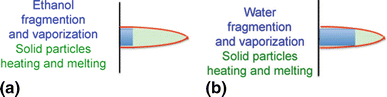
Suspensions behavior in a PTF4 type torch plasma jet: (a) ethanol based, (b) water based (Ref 64)

In both cases for spray distances z > 4 cm, molten particle velocities correspond to St < 1, but spraying at z < 4 cm generates heat fluxes up to 30 MW/m2 (Ref 67). Thus, particles within ethanol are rapidly freed, but Knudsen effect reduces their velocities and temperatures, while those within water are relatively well accelerated, thanks to their mother droplets, but poorly heated.
High-velocity suspension flame spraying (HVSFS) has been successfully performed with axial injection of liquid feedstock directly into the combustion chamber. Different types of industrial HVOF spray torches have been used, like TopGun or Diamond Jet Hybride. To adapt a torch to a liquid feedstock, the powder injector is replaced by an appropriate injection system. More recent developments work with modifications of the combustion chamber geometry to count for the specific combustion conditions due to the presence of a liquid solvent (Ref 69). Suspensions modify the combustion process that depends on the overall thermal power level of the torch, the type of solvent and the suspension feed rate. Thus, the combustion chamber geometry and barrel length should fit to the type of solid particles (particle size, melting temperature) and the type of solvent (water or alcohol). Fuel gases with higher combustion temperatures are necessary to provide enough energy for solvent evaporation and particle melting. Unsaturated hydrocarbons like ethylene and propylene are preferentially used for this purpose. In HVOF flame combustion, the Knudsen effect is negligible; thus, heat and impulse transfer to spray particles is much more effective than in SPS. Coating formation and microstructure depend on many process steps inside the torch: The way the liquid is injected into the combustion chamber (with or without atomization), the suspension fragmentation inside the combustion chamber, the type of solvent, the mass fraction and primary size distribution of solid particles. Simulations suggest that in some cases evaporation of solvent does not occur in the combustion chamber itself but near the expansion barrel entrance (Ref 69). Velocities at typical spray distances (80-120 cm) of the HVSFS process are in the range of 700-1100 m/s, and these values are significantly higher compared to those achieved by standard SPS processes.
Current Challenges and Advances in Science and Technology to Meet These Challenges
-
Suspensions and solutions preparation As pointed out by Toma et al. (Ref 65), the suspensions development should be tailored, through selection and dispersion of the raw material in the liquid to enable all requirements to be met, i.e., homogeneity, low viscosity (good flow ability), high content of solids, high stability of the suspension (neither sedimentation nor modification of the suspension composition), compatibility with the hardware components, long-term process stability. Decomposition and evaporation of feedstock material during suspension spraying can also occur and modify stoichiometry and phase composition of the deposits (Ref 70). It is the same way for solutions development; the challenges are (Ref 71): moderate deposition rates to evaporate the precursor solvent, precursor characteristics that influence the spray process (viscosity, endothermic and exothermic reactions, the sequence of physical states through which the precursor passes before attaining the final state, etc.).
-
What must be improved or developed in plasma spray torches? Conventional plasma torches produce plasma jets that, without liquid injection, have lengths <5 cm. Longer plasma jets are mandatory to achieve higher impact velocities of particles contained in suspensions. Works have been started in this direction using Triplex torch (Ref 72), torches with neutrodes to increase voltages over 100 V (Ref 73), torches with axial injection (Mettech) where high particle velocities are achieved (Ref 66). The axial injection of the suspension/solution in the plasma jet will definitely reduce the overspray particles and consequently improve the coating quality and process efficiency. For example (Ref 74, 75), the Mettech torch working with YSZ can generate coatings that are vertically cracked, porous, and exhibit a feathery columnar microstructure as electron beam physical vapor deposition (EB-PVD) coatings. For the axial injection, special attention have to be given to the injector development because there is a high risk of clogging if the parameters are not appropriately chosen.
-
What must be improved in liquid injection within plasmas? The trajectory control of drops or droplets implies that diameters and velocities could be controlled separately, which is unfortunately not the case actually. One of the net results is that small droplets with low velocities cannot penetrate the plasma jet, while the big droplets go through it thus not having time to evaporate
-
What must be improved or developed in HVSFS process?
-
Torch design: The HVSFS process (Ref 76) needs combustion chamber geometries to be adapted to specific carrier fluids to account for evaporation and possible combustion. The respective type of carrier fluid and the injection rate of the suspension have been shown to have a significant influence on the melting behavior of the powder particles. From an industrial point of view, water is preferred as an “easy to handle” solvent. However, for high melting temperature oxides, the use of organic solvents can be advantageous, but mostly with low concentrated suspension. Another issue is the relatively narrow window of parameters, which can be used to produce these coatings with desired properties. Lower differences between the melting point and the vaporization point of the material can strongly influence the process stability and coating properties through overspray effects.
-
Suspension properties play a crucial role in HVSFS process. Agglomerate size and overall stability of the suspension need a precise control for axial injection. Depending on the type of powders (e.g., oxides, metals) as well as their particles size distribution, individual formulations are mandatory to achieve optimal stabilization (Ref 77).
-
Injection of liquid: The HVSFS process needs furthermore a stable, reliable injection of the fluid against the high pressure in the combustion chamber, depending both on the suspension feeder and the injector itself. The axial injection of suspension can be achieved in form of fine jet stream of suspension or using two-fluid nozzle with atomization (Ref 65, 76). To achieve control of the droplet diameters formed during atomization, which in turn has a direct influence on the melting process of powder particles, a controlled atomization during the injection can be advantageous. Moreover, the use of two-fluid nozzle demands a supplementary cooling system (water cooled or gas cooled). Resulting coating properties like its microhardness, porosity level and pore size and surface roughness depend on a multitude of parameters within the suspension spray process: Most important are: solvent type, particle size distribution, type of injection, combustion chamber and nozzle geometry, fuel gas type, absolute gas flow parameters and lambda value (Ref 69, 78). Especially when spraying submicron- and nanosized particle-based suspensions, the gas flow effects on dedicated substrate geometries like edges or small asperities can lead to undesired microstructural effects not observed in spray powder-based processes.
-
-
What measurements should be developed for a better understanding of coating formation? Specific techniques must be used to study the coating formation and microstructural characterization. Most techniques used in conventional spray processes are no more capable of experimentally observing the liquid feedstock in spray process and of investigating the effect of the operating conditions on liquid fragmentation in droplets, solid particles released by solvent evaporation or formed from the chemical precursors (Ref 64, 79, 80). Problems are related to measurements of in-flight particles velocities and temperatures (Ref 64). The shadowgraph technique is also used to visualize liquid jet and droplets within the plasma jet and determine droplet number and size (over 5 μm) and also particle velocity in a given measurement volume. Velocity measurements of particles <5μm are now possible with particles image velocimetry (PIV) technique, but their temperatures can only be followed by ensemble measurements, which precision is poor (Ref 64). The mechanism of formation of coating architectures through the study of splats, beads and coating, studied for conventional coatings, is limited for particles above about 5 μm. At the last following, the flattening of particles below 5 μm is not yet possible. Thus, we are still far from measurements performed on particles in-flight and during flattening in conventional spraying, measurements which have drastically improved coating qualities.
-
Which are the issues to be considered for acceptance in the industrial spray shops of suspension and solution spraying processes? To be accepted at the industrial scale, several issues should be considered (Ref 65):
-
Feedstock: production method, commercial availability, costs, safety issues linked to the manipulation, transport, storage
-
Hardware components (gun, injectors, suspension feeder) and process stability (no clogging, long-time spraying), spare parts
-
Production of nanoparticles during spraying and their recycling
-
Substrate temperatures (very high) and spray distances (very short), especially for suspension plasma spraying
-
Economical aspects (deposition efficiency, coating per pass, suspension/solution concentration, feedstock flow rate, deposition time).
-
Solution Precursor Plasma Spray
Eric Jordan
Current State of the Field
Solution precursor plasma spray (SPPS) unitizes liquid chemical solutions injected into plasma or combustion jet in place of powder to create coatings. The process is schematically shown in Fig. 17. A related method to be discussed separately is suspension plasma spray (SPS) in which solid particles are suspended in a liquid and injected into the thermal jet.

A schematic of the solution precursor plasma spray process
Many issues in solution spray are shared with suspension spray. In both processes, there is a need to evaporate liquid solvents or carrier liquids, which is a very significant energy cost (Ref 81). In both solution and suspension spray, it is necessary to entrain the liquid feedstock into the thermal jet so that it can be effectively transformed into oxide particles. This can be done either using an atomizing injector where droplets are injected or using a stream injector where the liquid enters the thermal jet as a solid stream and is atomized by the cross-flow from the thermal jet (Fig. 18).

High-speed image of stream injection (left) and atomizing injection (right)
In both suspension and solution spray, the particle size arriving at the substrate is a consequence of initial droplet size after primary atomization, droplet break-up and merging, and the concentration of solid loading in a unit volume of liquid. The final arriving particle size is very critical to the final coating properties. In these processes, the size of the arriving material that created the coating is not easy to be controlled directly. The complexity of events determining the final delivered particle size is greater in the SPPS process compared to the SPS process because the chemical reactions present in the SPPS process can produce exothermic and endothermic events and changes in physical properties including the formations of gels and intermediate solid states. The exact nature of these changes depends on the specific precursors used, and as a result, successful precursor systems have to be developed one composition at a time.
In spite of the challenges, solution spray has been shown to be capable of generating a wide range of different oxide coatings. The coatings that have been reported in the literature include: yttria-stabilized zirconia (YSZ) thermal barrier coatings (TBCs) (Ref 82-84), YSZ coatings with nickel metal particles recovered by hydrogen annealing used in fuel cells (Ref 85, 86), Mn-Co spinel protective coatings for mitigating Cr evolution on SOFC interconnectors (Ref 87), La1−x Sr x MnO3 made by the SPPS process that avoided the occurrence of the troublesome sub-oxides found in conventional APS deposition (Ref 88), YSZ TBCs with metastable alumina solutes to improve CMAS resistance (Ref 89), gadolinium zirconate TBCs (Ref 90), ultra-high-temperature yttrium aluminum garnet (YAG) TBCs (Ref 91), porous titanium dioxide coatings (Ref 92) and a dense titania bioactive coating (Ref 93), phase-separated alumina-YSZ composite coatings (Ref 94), magnesia-yttria composite optical coatings (Ref 95), Dy- or Tm-doped YAG and Eu-doped yttria thermographic coatings (Ref 93-98). To date, most of these coatings are still in the development stages and not been used on a regular basis, with exception of thermographic phosphors that have been employed repeatedly in gas turbine experiments (Ref 96).
Advantages of Solution Spray
From these many different solution spray coatings, advantages and challenges related to this process have begun to emerge. In fact coating features that may be an advantage in one application can be a disadvantage in a different application and many of the features can be turned on or off depending on the processing details as will be noted in the following section.
-
1.
Rapid exploration of coating compositions
The feedstock for solution spray is a liquid chemical solution, in most cases an aqueous solution. There can be challenges finding compatible soluble chemicals to create a stable combination of needed cations. Soluble forms of metal ions in use are typically inorganic salts such as nitrates, chlorides and sulfates, but in rare cases organic salts, e.g., isopropoxides, acetates and propionates, are also utilized. Once a suitable solution involving one or more components is found, the compositional ratios can be rapidly varied by simply mixing the salts in different proportions. In comparison, fabricating different compositional ratios for powder spray typically involve creating the solid with different compositions and then creating a flowable powder suitable for thermal spray often by spray drying followed by heat treatment. Creating sprayable powder for each new composition is time-consuming. With solution spray, exploring a large number of coating compositions can be achieved in a single spray day, which provides a huge advantage of composition screening for a specific technical application. This advantage was exploited for example in determining optimal dopant levels for thermographic phosphors (Ref 94-96).
-
2.
Creation of through thickness stress-relieving cracks
In solution spray, it is possible by managing the injection process to have a fraction of the precursor to reach the substrate in a semipyrolized form. It has been shown (Ref 99) that a precursor when it subsequently pyrolized upon heating either during spraying or after will result in stress-relieving cracks (Fig. 19). Stress-relieving cracks can benefit thermal barrier coating performance 3, 4, including enabling very thick coatings that do not suffer a durability debit typical of conventional coatings due to low residual stresses (Ref 100) and by enabling the use of materials with relatively poorly matched thermal expansion properties with the substrate such as YAG which otherwise has excellent properties for a TBC.

YSZ thermal barrier coating with stress-relieving cracks and conductivity lowering interpass boundaries (IPBs)
-
3.
Creation of layered porosity for reduced thermal conductivity
In the solution spray process, under the correct process parameter choices, porosity concentrated in planar layers, termed interpass boundaries (IPBs), can be created. Generally this will occur when the offset between passes is on the small side. These features shown in Fig. 3 have been shown to reduce the thermal conductivity of YSZ TBCs roughly by a factor of 2 while still maintaining good thermal cyclic durability and erosion resistance (Ref 101).
-
4.
Creation of finer-scale two-phase microstructures
Because in solution spray the coating constituents are delivered in a homogeneous molecularly mixed form and then rapidly melted and rapidly solidified as in any thermal spray process, both metastable forms and fine-scale phase-separated microstructures can be made. One example of a useful metastable phase is the formation of a solution of alumina in YSZ where the equilibrium phase diagram predicted zero solubility, but solution spray created dissolved alumina up to 20 mol.% and metastable solid solution was stable up to approximately 1200°C. An example of fine-scale composite coatings is shown in Fig. 20 which shows an alumina zirconia composite with submicron phase domains.

Alumina-zirconia two-phase coating with small phase domains made by solution precursor plasma spray
-
5.
Adding chemical energy to aid deposition
In both SPPS and SPS processes, the evaporation of liquids limits the deposition rate and often presents a challenge of getting the desired degree of melting. In the conversion of precursors to melted ceramics, scanning calorimetry indicates that in addition to the endothermic events expected that include evaporation of the solvent, heating the ceramic and the heat of fusion, very significant chemical energy can be generated if a combination of reducing and oxidizing precursors is used together which can aid both melting and deposition rate. Shown in Table 1 (Ref 102) is an example involving a nitrate and acetate combination where chemical energy of reaction 531 J/g is of the same order as the heat of fusion of aluminum oxide (1360 J/g). This has been shown to improve deposition in cases where extra heating is helpful. Our experience shows that there is an optimal amount of chemical energy beyond which it may cease to help the coating deposition process or even disrupt it. Chemical energy can also be added using chemicals that do not end up in the coating, for example adding urea or ammonium acetate to a nitrate-based precursor.
-
6.
Production of a fine microstructure with higher fracture toughness
In the case of YSZ thermal barrier coatings, solution spray coatings are shown to have 5× higher in plane fracture toughness by indentation (Ref 98) which is assumed to be related to the very fine microstructure. This might be part of the explanation for why layered coatings with 20% porosity were found to have comparable erosion resistance to APS coatings.
Challenges
Solution-sprayed coatings have a number of desirable characteristics as just enumerated. There are also a number of significant challenges.
-
1.
Lower deposition rates
In making solution-sprayed coatings, it is observed that even with reasonable deposition efficiency 50% or higher, the deposition rate is generally much lower than for powder spray. In the best cases, for example for YSZ, the weight fraction of equivalent oxide in the solution is around 22%. This means that for a given amount of ceramic there is 5× more materials injected into the torch to process a given amount of powder compared to powder injection, and in the case of an aqueous solution, the single largest energy contribution needed to create the melted oxide from the solution goes into the evaporation of water. Even with the chemical energy from combined oxidizer-reducer precursors, the deposition rate is generally 2× or more, lower than with powder spray. This leads to a higher production cost.
-
2.
Shorter standoff distances
Solution spray requires a shorter standoff distance from the torch exit to the substrate. This imposes a disadvantage with coating complex shaped parts where the torch cannot be made close to some surfaces especially for turbine vane doublets and cascades. We have found that the standoff distance needed ranges from about 4 cm up to 8 cm in the ideal case typically half the distance used in powder spray. Generally longer standoff distances are possible with larger higher power torches and more energetic precursors. A number of discussions with suspension spray practitioners indicate that the standoff distance in suspension spray is somewhat larger. The reason for this is not clear at this time.
-
3.
Each new composition is a new challenge
Each precursor is a new challenge. As mentioned in the introduction, the sequence of physical states that a solution precursor undergoes affects the final delivered particle size which is a system-specific process. In some cases, finding a high-molarity affordable precursor is a challenge. For titania, we used a rather expensive precursor consisting of titanium isopropoxide and ethanol in which the equivalent weight fraction of oxide in the precursor is only 10% (Ref 103). In other cases, unexpected differences in behavior arise from related precursors are seen. We have found the zirconium acetate, yttrium nitrate precursor, used for YSZ to be much better behaved than the yttrium nitrate, aluminum acetate precursor, in spite of the similarities. Also like powder spray in some not very frequently occurring cases, there can be selective loss of one element relative to another, there is very modest greater loss of the aluminum precursor relative to the yttrium one when making YAG, while in magnesia-yttria composites we have observed up to 85% loss of the magnesium relative to the yttrium (Ref 104). Magnesium loss is also known to also occur in powder spray. It is then a characteristic of this process that within a given composition one can rapidly vary the component ratios but with each new composition come new challenges in finding a suitable precursor and getting it to work. It is often necessary to add components to the precursor to increase viscosity, for example poly vinyl alcohol, or add fuel to an oxidizing precursor like adding urea or ammonium acetate to the precursor to make it more energetic.
-
4.
Lack of good particle diagnostics for solution spray
The droplet injected in solution spray typically has a mean size of about 20 microns; however, the melted ceramic form in which the coating is made of is generally in the size range of low single digit micron or even smaller. As a result, previously developed plume diagnostic instruments based on individual particle measurements for the powder spray provide a limited insight into the solution spray process, as the smallest in-flight particle size can be detected by such diagnostic devices is about 5 micron (Ref 105, 106). Particle velocity and temperature measurement of individual particles has not been achieved in any commercial instruments. This measurement is extremely challenging due to the very large number of very small particles involved. Radiation pyrometery can get some sort of ensemble average temperature; however, with intensity changes with the forth power of the temperature these measurements are likely to be biased to the largest hottest particles, and to date, velocity of individual particles cannot be measured with commercially available instruments.
Advances in Science and Technology Needed to Meet the Challenges
It is likely that the challenge of finding suitable precursor for each new composition will be advanced on a case by case basis and considerable progress has been made here and should continue to be made. The lower deposition rate may advance with higher molarity precursors. Such precursors often come with high viscosity and special technology to deal with as this is necessary for a high-pressure liquid delivery system. Better energetics for the precursor has shown some promises for improving deposition rates as well. We note, however, that the energy needed to be added at the correct point in the process, producing extra heat in the plum far down stream that is still below the melting point of the materials in questions, may be more harm than good as it can create over heating of the substrate without the full benefit on melt state desired. Recent experiments show that alcohol generally burns significantly downstream from its injection point (Ref 107). The challenge of the shorter standoff distance has seen some improvement using more stable, high energy torches as well as more energetic precursors; however, there is much yet to be understood. If the reason why suspension spray distances are larger can be determined, then insight may lead to further improvement in the solution precursor plasma spray. A better understanding of this process will be greatly aided by the development of viable particle diagnostics that can provide particle temperatures and velocities. As with all coating processes, the ideal process depends on a combination of cost and performance factors and the three strongest cases for the use of solution spray can at this time be made for making TBC with stress-relieving cracks, making thermographic coatings and most significantly for the rapid exploration and optimization of new compositions.
Plasma Sources Development and Modeling
P. Fauchais, M. Boulos, J. Mostaghimi, and J.P. Trelles
Thermal spray including plasma spraying, today employed in many fields, has become one of the leading surface modification technologies alongside physical vapor deposition and weld overlaying (Ref 108). This development resulted from both industrial-scale integration of the technology working in air, controlled atmosphere or soft vacuum (recently down to pressures of 0.1 kPa) and research with process modeling and measurements of plasma, particles in-flight and coating characterization.
Arc Plasma Torch Modeling
Modeling is a powerful tool for the development of plasma sources in the thermal spray industry. It allows for the prediction of the flow, temperature and concentration field in the discharge and the associated electromagnetic fields. It allows also for the prediction of the thermal load on the electrodes and the plasma confinement environment. With the rapid development of computing power, modeling has evolved rapidly over the past decade allowing for its use on a regular basis in source or process developments. Model validation has generally lagged behind due to the experimental challenges meeting under the harsh environmental conditions near the arc. While a wide range of diagnostics tools are available, considerable more effort needs to be devoted to the validation of model predictions against reliable experimental data.
Arc phenomena in arc plasma torches are strongly linked to working conditions and flow fields. Unfortunately, measurements inside the torch are rather limited and most understanding has been obtained from models. Plasma torch models can be loosely divided among detailed (e.g., multidimensional) and reduced (e.g., lumped), each aimed to different aspects of process modeling.
Detailed models are required for the exploration of plasma dynamics and for equipment or processes design. These models are often time dependent and three dimension in order to capture the complex arc dynamics and plasma gas flow interactions (Ref 109, 110). The use of models that depart from the local thermodynamic equilibrium (LTE) assumption in favor of non-LTE (NLTE, such as two temperature) descriptions has demonstrated to produce better agreement with experimental observations (Ref 111), particularly of the frequency and amplitude of voltage fluctuations. The use of NLTE models requires the calculation of non-equilibrium thermodynamics and transport properties, which can constitute a significant computational expense (Ref 112). Moreover, non-local chemical equilibrium (NLCE) models should be adopted when molecular gases or gas mixtures are used (e.g., (Ref 113). NLCE models require determining kinetic coefficients of forward and reverse reactions, which can be highly computationally expensive. To simplify calculations, it is possible to perform stationary kinetic calculations neglecting diffusion and convection or using pseudo-equilibrium approximations (Ref 114-116). The results in all of these cases, while rather interesting, need further validation against experimental data for general conclusions to be drawn.
A more adequate description of plasma-electrode interaction phenomena from what is typically found in arc plasma torch models can be achieved by including the electrodes within the computational domain (Ref 117), which is especially relevant for describing heat transfer to the electrodes as well as electrode erosion. Fluid flow models for plasma spraying need to account for plasma-environment mixing (e.g., cold flow entrainment) and the occurrence of spatial-temporal turbulent phenomena. Traditionally, Reynolds-averaged Navier-Stokes (RANS) models, which describe time-averaged flow characteristics (e.g., k-ε model), have been widely used for plasma spray modeling. Nevertheless, these models often require several empirically determined model constants and therefore provide limited predictive capabilities.
Furthermore, these models have often been formulated for conditions not appropriate for the description of plasma flows, such as constant properties and incompressibility. The dynamic flow conditions found in plasma spraying are more adequately described by so-called large Eddy simulation (LES) techniques, which use simpler or fewer modeling assumptions (e.g., such as the universality of energy dissipation by the smallest flow features), but often require significantly larger computational resources (Ref 118). Including turbulence effect on Lorentz force and Joule heating terms should be considered. In spite of many sophisticated turbulent models for the plasma flow, this effect on electromagnetic fields is ignored. It may turn out that the effect is not important; however, it is important to demonstrate this in future work.
Reduced models, which only provide a limited amount of fidelity, are more appropriate than detailed models for process optimization or real-time monitoring and control. Reduced models can be obtained from simplifications of detailed models (e.g., reduced dimensionality, geometric complexity, steady state) combined with empirical understanding. An example of such model reduction approach is the of the Helmholtz resonator concept to correlate pressure fluctuations inside the torch with the obtained voltage fluctuations (Ref 119, 120). Another approach consists on using model order reduction methods, which condense the original set of equations from the detailed model into a smaller set that is simpler to solve. Alternatively, purely algorithmic approaches, which do not rely on the physical/mathematical description of the process, can be used. Examples of these are methods-based characterization/estimation such as neural networks.
Challenges for the Improvement in DC Plasma Torches
Traditional DC plasma torches used for spray coating applications are in the category of non-transferred arcs and include a thermionic (hot) cathode and a ring anode. The cathode material is normally thoriated tungsten. Plasma gases used include argon and nitrogen with hydrogen or helium to enhance the thermal conductivity. If cathode attachment in such torches is rather stationary, it is not the case at the anode (Ref 121). The arc current is controlled and maintained constant, and thus, voltage varies between the minimum V min and maximum values V Max (ΔV = V Max − V min) with plasma gases composition and flow rate. One of the important issues that affect particle heating is the fluctuation of the arc voltage especially with gases containing diatomic species (restrike mode). The voltage fluctuation, and thus power dissipated, can reach ΔV/V m=1, V m being the mean voltage. This phenomenon is related to the arc attachment at the anode and the existence of different resonant modes with the possibility of their coupling (Ref 123). Minimizing the amplitude of such fluctuations will improve the consistency of particle heating and results in better control of the deposition process.
A number of different designs have recently been developed, and some of these have been commercialized (Ref 16). A CO2/CH4 torch with highly structured graphite cathode was recently developed (Ref 17). Due to the nature of the plasma gases, arc voltage is rather high. This allows the torch to be operated at low currents resulting in long electrode life. In the case of this design, a balance between graphite sublimation and deposition of carbon ions on the cathode is achieved which makes for a long cathode life. Carbon is deposited in the form of carbon nanotubes (Ref 124). The advantage of these gases for spraying is their large thermal conductivity at higher temperatures (~7000 K) and their large enthalpy, resulting in more powder to be heated, hence higher productivity. With thermal efficiency of these torches, up to 85% and low-temperature fluctuation heating of the powders is very good. An important advantage of high enthalpy plasma gases is that locally they do not easily cool down because of the injected materials.
Another high enthalpy torch is the liquid-stabilized DC plasma torch developed by Hrabovsky et al. (Ref 125). The reported maximum plasma power was 160 kW, current of up to 500 A, with an exit centerline plasma velocity of up to 7 km/s and a plasma temperature of up to 22,000 K. While the main application of the torch has been in biomass gasification, this torch has also been employed in high throughput (i.e., up to 100 kg/h of metal powder at 160 kW plasma power) plasma spray coating applications.
Achieving torches working with high enthalpy is particularly important for the case of suspension plasma spray (SPS) and solution precursor plasma spraying (SPPS) where evaporation of the solvent is energy intensive. Recently the current limitations of the technology (Ref 126) and interaction of the liquid drops with the plasma and their evaporation were reviewed (Ref 127).
DC torches with cascaded neutrodes offer numerous advantages over ordinary guns. Due to its longer arc length, the mean voltage V m is higher, and as the voltage fluctuation at the anode is the same as with no neutrode, ΔV/V m < 0.2-0.5. Oerlikon-Metco’s SinplexPro (Ref 128) is an example of a commercial torch with a single cathode and a cascaded anode.
Oerlikon-Metco’s Triplex (Ref 129) torch has three cathodes and a cascaded anode. The torch voltage is high and its current low. The voltage fluctuation is of the order of ±15%. The powder is still injected from the exit of the nozzle by up to three ports. Movement of anode attachment points, which affects optimum introduction of powders, is reported to be one problem for Triplex.
Another interesting multielectrode torch design with a single cathode and three cascaded anodes is the so-called Delta Gun, commercialized by GTV Gmbh (Ref 129). In this gun, the voltage fluctuation is reported to be only ±3 V. In Delta Gun, the anode roots are fixed, and thus, the position of the powder injections ports may be fixed. There is, however, some instability, which is associated with axial fluctuations of the arc separation point (Ref 130).
In all the above-described torches, powders injection is radial downstream of the torch nozzle The Axial III torch developed by Northwest Mettech Corporation is designed for central injection (Ref 131). The torch comprises three DC plasma torches where plasma jets created by each torch enter a nozzle forming a single plasma jet. Material is then injected into the center of this jet. This central injection results in high deposition rates and completes melting of the injected powders. Central injection is particularly attractive in SPPS and SPS. Interaction of the three plasma jets plus the powder carrier jet generates a high degree of turbulence and a higher pressure where these jets meet. This condition may cause some smaller size particles to travel upstream within the torches and toward the cathode. Additionally, because of turbulent dispersion, some finer particles, which are more affected by turbulent dispersion, may be deposited on the nozzle walls.
RF Induction Plasma Torch Developments
Among the wide range of plasma torches used in thermal spray applications, induction plasmas have been recognized as being a valuable tool for niche applications. Their main advantage is in their ability to insure the highest level of purity in the deposit and the ability to melt and deposit powders with relatively large particle sizes and achieving high coating densities. They are also well suited for powder synthesis and processing as well as in solution and suspension plasma spraying.
Modeling has played a key role for the prediction of the flow and temperature fields in the discharge region of the torch and the estimation of the heat flux profiles to the different components of the torch and the estimation of process performance under different operating conditions (Ref 132).
The main challenges meet in modeling induction plasma torches are;
-
Relatively complex 3D electromagnetic fields, which has a significant influence on the flow and temperature fields in the discharge (Ref 133-135).
-
The presence of a mixed flow region with the flow in the center of the discharge being laminar with highly turbulent flow in its fringes near the walls of the plasma confinement tube (Ref 136-138).
-
Because of the commonly used mode of axial injection of the material to be processed in the center of the discharge, these are a strong interaction between the process conditions and the condition in the discharge. The partial evaporation of the processed material and the mixing of its vapor with the discharge is a typical example (Ref 139, 140).
-
The strong interaction between the electromagnetic properties of the discharge and the power supply, which raises the need for rather complex models taking into account the power supply circuit characteristics (Ref 141).
-
Limited experimental data including flow, temperature and concentration field measurements for model validation under a wide range of conditions. With few exceptions, model validations have often been limited to energy balance data (Ref 142-144).
Coating Properties and Functions
Functional Oxides
S. Sampath and K. Shinoda
Current State of the Field
Functional metal oxides are important classes of materials that display insulative, semiconductive, conductive (electronic, ionic or mixed), magnetic and even superconducting behavior. In general, these materials are complex multicomponent systems, and their electrical characteristics are achieved via manipulation of the defect chemistry imposed through alloying. Due to their unique characteristics, they have been a subject of significant interest in electronics, sensors and energy systems (Ref 145-147). A common attribute among these applications is the desire to fabricate these materials in the form of thin films or as thick film multilayers so as to harness their capabilities within devices. Numerous applications now exist which utilize such devices including RF/microwave systems, power electronics, sensors, batteries and fuel cells. Materials of interest include doped zirconias, ferrites, indium-tin oxide, doped manganites and titanates. Wide ranging future opportunities are foreseen utilizing these materials, especially those related to high-temperature and harsh environment applications (Ref 148-153).

Process map approach for optimizing coating properties of plasma-sprayed manganese zinc ferrite: the effects of particle velocity (V) and temperature (T) on FeO formation (χFeO), Zn loss (χZn-loss), saturation magnetization (M S ), coercivity (H C ) are shown (adapted from Shinoda et al. (Ref 166))

Microstructures of complete solid oxide fuel cells partially manufactured with atmospheric plasma spray (photo courtesy: Dr. Robert Vaßen, Juelich Research Center, Juelich, Germany)
Thermal spray offers several strategic advantages in terms of thick film processing of functional oxides (Ref 154). Unique attributes include:
-
In situ application of metals, ceramics, polymers or any combinations of these without thermal treatment or curing, incorporating mixed or graded layers
-
Cost-effective, efficient processability in virtually any environment (ambient to vacuum)
-
Limited thermal input during processing allowing deposition on range of substrates
-
3D capability using robotics allowing functional deposits directly on actual structures
-
Green technology vis-à-vis plating, lithography, etc. (all solids processing with powder recovery)
The fabrication of functional oxides by thermal spray is a key to shifting thermal spray applications from traditional protective coatings to enhanced functional surfaces. The majority of present-day thermal spray applications are in the field of protective coatings, where the principle function of the overlay coating is to protect the underlying substrate from heat, contact damage (e.g., wear) or the surrounding operational environment (corrosion) (Ref 154). Thermal barrier coatings for protection of hot section superalloys in energy and propulsion gas turbines are the most widely recognized oxide systems. In most of these situations, the coatings can at best be classified as “passive materials” and typically do not contribute to physical or chemical functional response other than providing a barrier function. As such, the applications of thermal spray in truly functional systems, that is, where the deposited materials must provide an electronic or sensory function, are to date limited in scale and scope. However, new opportunities are now emerging in advanced functional surfaces, including dielectrics, electrical conductors, bioactive materials and solid oxide fuel cells. In these new applications, thermal spray offers advantages for manufacture of deposits over large area substrates and for the creation of complex conformal functional devices and systems. Perhaps the most significant current functional application of thermal spray lies in the manufacture of solid oxide fuel cells, involving layered material architecture of high-temperature oxides with metals (Ref 155). Other potential applications are electronic sensors, direct writing technologies, energy-related applications such as thermoelectric generators (Ref 153, 154). Environmental barrier functions may also be considered as applications of functional oxides, because they require a function to response to invading material in addition to traditional passive protection in advanced turbine systems (Ref 156).
Current Challenges
Functional oxides are usually provided in the following forms: bulk sintered compacts, thin films, thick coatings and their multilayers. Thermal spray coating technologies can accommodate these requirements by adaption to thin film technologies such as plasma spray-PVD in addition to traditional plasma spraying or HVOF spraying for producing thick coatings and spray forming of bulk materials.
Wide variety of functional oxides have been tested so far: dielectrics (insulators) (e.g., BaTiO3, Al2O3) (Ref 157, 158), ferroelectrics (PZT (lead zirconate titanate)) (Ref 159), magnetic materials (ferrites) (Ref 160), semiconductors (TiO2) (Ref 161, 162), electronic/ionic conductors (resistors) (NiO, LaMnO3, MnCoO4) (Ref 163), superconductors (Y-Ba-Cu-O) (Ref 164) and composites (Ni/ferrites) (Ref 165). Sensory and photocatalytic applications have also been contemplated (Ref 161). Successful commercialized cases are limited to dielectric insulators, oxygen sensors and interconnect protective coatings based on manganites in fuel cells.
Fabrication of functional oxide coatings by thermal spray is still challenging, and properties of the oxide coatings are yet to be improved to those of bulk materials. Thermal spray can cause significant deviations of the performance from the desired bulk material. Currently, the following deterioration mechanisms are reported.
-
1.
Formations of globular/interlamellar pores and micro/macro cracks: traditional thermal spray coatings are generated by integration of melt-quenched splats. This process typically introduces pores and cracks in the coating microstructure, which usually causes deterioration of coating qualities from bulk properties. For example, decrease in dielectric breakdown voltage in insulators and gas leakage in dense solid electrolyte in SOFCs are reported.
-
2.
The preferential evaporation of the metallic elements of which vapor pressure is high: In functional oxide applications, proper composition of metallic elements and ability of dopant introduction are key to maximizing the performance. However, in plasma spraying of complex oxide powder, powder particles experience high heat flux and strong gradients from thermal plasmas during flight. Elements with higher vapor pressure tend to evaporate more compared to other elements. This phenomenon can be significant for smaller sized particles so it becomes more complicated when powder size distribution is considered.
-
3.
Reduction in oxidation state can occur: In many semiconducting oxides, oxygen loss can occur during particle flight in plasma. This reduced oxygen status can be preserved upon splat formation due to rapid quenching, which can induce secondary phase formation. Post-annealing process can recover or adjust the oxygen content to some extent, but the annealing condition is usually restricted by the existence of metallic parts or substrates and associated challenges with maximum allowable temperatures and thermal expansion mismatch.
Advances in Science and Technology to Meet These Challenges
Improvement in Traditional Thermal Spray Processes
Conventional thermal spray such as plasma spray and HVOF is a well-established technology to form oxide coatings. As such, the concepts learned in optimizing protective coatings can be extended to functional oxides with added requirements of controlling stoichiometry, phase and oxidation states (Ref 162). The application of process diagnostics and control for deposition of functional oxides with keeping deterioration of in-flight particles minimized during processing is generally the first approach. The concept of a process map derived from deliberate exploration of process maps coupled with in situ diagnostics is useful to investigate the process improvements when coupled with both microstructural and functional measurement. In this method, in-flight particle state parameters such as particle velocity and temperature are introduced to interpret process conditions. A relationship between process input variables and coating properties is interpreted via in-flight particle state parameters. Selection of the process input variables and the design of experiments to produce the process map are based on the physics in plasma-particle interaction. An example of an integrated process map concept that couples functional properties with stoichiometry, oxidation and microstructure is illustrated in Fig. 21 for plasma-sprayed manganese zinc ferrite thick films (Ref 166).
Similar approaches are envisaged to simultaneously optimize phase structure, stoichiometry, density and therefore both electrical properties and protection capability of plasma-sprayed La0.8Sr0.2MnO3 or Mn1.5Co1.5O4 coatings for metallic interconnects in solid oxide fuels. In two papers, Han et al. showed multifunctional optimization strategies for both of the oxides through combination of stoichiometry control and preferred phase retention (for ensuring requisite electrical conductivity of the interconnect coating) while also promoting high density to impart oxidation protection to the underlying ferritic steel interconnect (Ref 167, 168). This development provides a framework for expanded utilization of functional oxides via thermal spray.
Applications of Functional Oxides Via Thermal Spray
For many decades, researchers have contemplated the use of thermal spray methods for synthesis of fabrication of solid oxide fuels components and even complete cells. In the 1980s and 1990s, Westinghouse Research which was subsequently acquired by Siemens conducted extensive development to fabricate the electrolyte, cathode and interconnect layers in tubular fuel cells (Ref 169). Although the technology as a whole was not successful, the role of thermal spray was significantly enhanced. Many other contemporary industrial and organizations continue to be engaged to develop thermal spray as a process of choice for SOFC component (Ref 170).
One example of integrated research demonstration from the Juelich research group is shown in Fig. 22. Here a complete fuel cell was built on porous ferritic steel substrates (Ref 155).
Another potential application is large area photocatalytic coatings based on anatase TiO2 for environmental degradation of harmful pollutants (Ref 171). A key issue for thermal spray is the ability to retain the anatase structure. It has been observed that traditional melt deposition TiO2 coatings via thermal spray generally result in the rutile polymorph and result in reduced photocatalytic performance. Increasing the melt status tends to reduce the anatase content of the coatings; however, the fundamental mechanisms are unclear at this point (Ref 172). This is clearly an area for continued fundamental studies (Fig. 23).
It is clear that in order to realize functional applications of thermal sprayed ceramic coatings, considerable efforts in understanding metastability, chemical imperfections and microstructural defects will be required in the future.
Development of New Processes
A new capability has emerged in recent years which can potentially enable expanded development and application by overcoming certain limitations of traditional thermal sprays. Liquid-fed thermal spray processes either using suspended ceramic particles in a liquid or a molecularly mixed precursor solutions enable synthesis of nanostructured and in some cases metastable oxides. For instance, in the case of TiO2 suspension plasma-sprayed allows retention of the preferred anatase (Ref 173). Solution precursor plasma spray processes have allowed synthesis of luminescent phosphors through strategic doping of rare earth elements in oxide matrices (Ref 174). Suspension- and solution-based processes also engender unique microstructures as seen in zirconia-based thermal barrier ceramics. These emergent opportunities will significantly enable and extend capabilities of thermal spray in functional oxides.
Functional Coatings
J. Mostaghimi, A. McDonald, and A. Dolatabadi
Developing new applications for thermal spray coatings and accordingly customizing conventional spray processes are essential in strengthening the field and expanding its market. In the following sections, five such applications are described.
Superhydrophobic Coatings
Superhydrophobic surfaces exhibit superior water repellant properties, thus possessing remarkable potential to improve current energy infrastructure (Ref 175). For example, a promising solution to icing problems is the use of superhydrophobic coatings that can delay or completely prevent ice formation on critical surfaces such as aircraft wings, engine nacelles and wind turbine blades (Ref 176). Superhydrophobicity of a surface is the result of low surface energy that is in turn the result of a combination of surface chemistry and surface micro-/nanomorphology. Commercial superhydrophobic coatings that rely on the low surface energy of polymers characteristically suffer from poor mechanical properties and are short-lived. On the other hand, finely textured surfaces are typically too complicated and costly to be applied on surfaces such as the wings of an aircraft.
Thermal spray processes provide promising solutions to develop durable superhydrophobic coatings. Harju et al. (Ref 177) investigated the wettability of various oxide ceramic coatings deposited by plasma spraying and concluded that, as sprayed, all those coatings were hydrophilic. The authors noted the now well-known effect of surface atmospheric airborne contamination on changing wetting behavior and increasing contact angle of the coatings. Teisala et al. (Ref 178) used a liquid flame spray process to deposit TiO2 nanoparticle-based superhydrophobic coatings on paperboard. Due to large contact angle hysteresis, droplet mobility on these coatings was not satisfactory in spite of the high contact angle values. Using air plasma spray, Li et al. (Ref 179) introduced coatings comprised of Fe, Ni and Cr that are hydrophilic as sprayed, but will eventually become superhydrophobic by simply being exposed to the ambient environment for up to 30 days. The authors attributed this phenomenon to the presence of partially oxidized metals that adsorb carbon-based compounds from the environment, which causes a change in the wettability of the surface.
The approach of creating textured surface morphologies using thermal spray processes and further treating the surface by an organic solution is recently introduced by few researchers. In an interesting work, Bidkar et al. (Ref 180) [also a patent application (Ref 181)] developed random-textured coatings using suspension plasma spraying further surface treated with Teflon and fluorosilane that demonstrated significant low friction and drag reduction in turbulent flow regimes. Gentleman et al. (Ref 182) showed examples of thermally sprayed rare earth oxide (REO) coatings with hydrophobic behavior in their coatings patent. Recently, Sharifi et al. (Ref 183) developed hierarchical morphologies in TiO2 superhydrophobic coatings by engineering the precursor suspension in a suspension plasma spray process. In another recent work (Ref 184), a stainless steel mesh was used as a shielding plate in atmospheric plasma spray to develop cone-shaped topographical features, further covered by suspension flame-sprayed polytetrafluoroethylene/nanocopper mixture to create superhydrophobic coatings.
Finally, the solution precursor plasma spray (SPPS) technique was successfully implemented by Cai et al. (Ref 185) to deposit ytterbium oxide on stainless steel substrates. Ytterbium oxide is a rare earth oxide which is naturally hydrophobic, inert, stable at high temperatures, and has good mechanical properties (Ref 186). The as-sprayed coating demonstrated a hierarchically structured surface topography, which closely resembles superhydrophobic surfaces found in nature. The water contact angle on the SPPS superhydrophobic coating was up to 65% higher than on smooth REO surfaces.
Although the development of superhydrophobic coatings via thermal spray is very promising, the remaining challenges to increase its technology readiness level would be i) to improve the coating durability under harsh conditions, ii) to better understand the correlation between superhydrophobic and icephobic coatings and iii) to engineer icephobic coatings.
Coatings as Heating Elements
Ice formation and accumulation on structures that are exposed to cold and humid ambient environments are a common problem, especially in the wind turbine industry (Ref 187). It has been shown that ice accretion affects the wind turbine blades by decreasing performance, safety and durability. On wind turbines, ice accretion has been found to produce mechanical and electrical failures, errors in the measurement of temperature, humidity, wind velocity, overproduction, and power losses of up to 50%. It is, therefore, imperative that solutions are developed to mitigate or eliminate the adverse effects of ice accumulation on structures used in wind turbines in order to increase overall safety, ensure integrity of the turbine components and improve overall performance of the wind turbine in cold environments. Similar concerns have been expressed in the aerospace industry to protect aircraft wings and engine nacelles.
Active anti-icing systems, to prevent the initial accretion of ice on the structures, have been developed (Ref 188), and some include the use of electrical heating wires embedded within the structure (Ref 189), indirect heating with warm air inside the structure and heat conduction to the surface, and microwave heating (Ref 190). These methodologies have inherent problems, which include positioning of the heating wires in the blade to avoid potential structural issues, the generation of high dynamic loads and the creation of localized “hot spots” on the surface, which could lead to high-temperature degradation of the structure. Additionally, microwave heating has never been successfully implemented. In some cases, surface modification work with the use of superhydrophobic coatings has been explored to improve the efficacy of anti-icing features of the material surfaces.
Thermal spray processes may provide an alternative method to fabricating heating elements for airfoils and wind turbine blades that are exposed to extreme cold climates. Lamarre et al. (Ref 191) have assessed and modeled the performance of FeCrAl wire-fed flame-sprayed coatings as heating elements on titanium substrates, obtaining temperatures above 450°C when 5 W/cm2 of power was applied. More recently, the application of thermal spray processes to fabricate coatings on fiber-reinforced polymer composite (FRPC) structures has been initiated. FRPCs are usually selected for a wide variety of applications in the aerospace and energy industries due to their large strength and stiffness to weight ratio, flexible manufacturing processes and cost (Ref 192); however, their thermal properties typically do not allow them to conduct heat rapidly. To that end, Rooks (Ref 193) proposed the use of plasma spraying in the fabrication of resistive heater elements for ice protection of the leading edge portion of the main rotor blade of a military helicopter. Lopera-Valle and McDonald (Ref 194) investigated the possible application of flame-sprayed nickel chromium aluminum yttrium (NiCrAlY) and nichrome (Ni-20Cr) coatings deposited onto FRPC parts for de-icing applications. It was found that the electrical resistance of NiCrAlY and Ni-20Cr coatings was between 3.2 and 3.6 ohms. Electrical current was applied to the coatings to increase the surface temperature by resistive (Joule) heating. The surface temperature profiles of the coatings were measured under free and forced convection conditions at different ambient temperatures, ranging from −25 to 23°C. It was found that at ambient air temperatures below 0°C, the surface temperature of the coating and in some cases that of the FRPC remained above 0°C for both the forced and free convection conditions. In addition, there was a nearly homogeneous temperature distribution over the coating surface. This suggested that flame-sprayed coatings may be used as heating elements to mitigate ice accretion on polymer-based structures, without the presence of areas of localized high temperatures. An existing implementation in industry is in the de-icing system integrated into the Boeing 787 Dreamliner carbon fiber-reinforced polymer (CFRP) composite wing based on a proprietary thermal spray deposition technique developed by GKN Aerospace (Redditch, U.K.). This application comprises thermal sprayed metal coatings deposited onto a fiber-reinforced polymer ply to create a resistive heater mat, which is embedded into the aircraft wings.
Coatings as Cathodes for Hydrogen Production
In recent years, hydrogen has received wide attention for use as a renewable energy carrier due to the increasing concerns about depletion of conventional energy resources, greenhouse gas emissions and global warming. Although alkaline water electrolysis is considered as one of the most promising techniques for producing high-purity hydrogen, the high costs of the electrolyzers and the high energy consumption of this process have limited its application for large-scale hydrogen production. Several methods have been used to improve the energy efficiency of the electrolysis process by reducing the hydrogen evolution overpotentials, such as using electrocatalysts with high intrinsic activities and large specific surface areas (Ref 195). In this regard, Raney nickel has been widely investigated as the electrode material due to its superior electrochemical performance for hydrogen evolution reaction (HER), owing to its large effective surface area obtained by the leaching process. The active surface area of an electrode can also be enhanced by morphological modification and increasing the surface roughness, which can be controlled by the method which is used for its production.
Conventional methods for fabricating electrodes for the HER include electrodeposition, thermal decomposition, plating and sintering. However, there are considerable drawbacks associated with using some of these methods, including undesired decomposition reactions, limited coating thickness and multiple production steps. Thermal spray is a promising technique that allows deposition of cost-effective coatings at high deposition rates in order to produce efficient electrodes for HER. Several studies have been conducted on using different thermal spray techniques for the development of nickel-based electrode coatings for the HER.
Hall (Ref 196) and Birry et al. (Ref 197) showed that lower overpotentials and reduced Tafel slopes were obtained for plasma-sprayed nickel and Raney nickel electrodes, respectively, compared to the sintered ones with similar compositions. Schiller et al. (Ref 198) developed highly electrocatalytic active Raney nickel-molybdenum cathode coatings by vacuum plasma spray with long-term stability under intermittent conditions up to 15,000 h. Fournier et al. (Ref 199) related the high activity of wire arc-sprayed Raney nickel and nickel-titanium electrodes to the increased active surface area and high level of porosity of the coatings. More recently, the effect of spraying parameters for different thermal spray processes and the resulting surface morphology of the deposited nickel electrodes on their electrocatalytical activities were investigated by Aghasibeig et al. (Ref 200-202). For this purpose, they engineered the surface morphology of the electrodes by deposition of three-dimensional fin arrays and obtained the highest electrocatalytic activity for the electrode that was deposited using the high-velocity oxy-fuel (HVOF) spraying process. The high activity of this electrode was related to the increased surface area and surface roughness that was created by the deposition of off-normal impinging particles, as well as lower oxidation of this coating compared to the plasma-sprayed electrodes. Due to the high capability of thermal spray processes to produce highly electrocatalytic active electrodes for the HER, more studies are required in this field to improve the efficiency of water electrolysis process further.
Antibacterial Coatings
For centuries, copper has been known as a material that could prevent the growth of weeds, which are wild herbaceous plants, on the hulls of ships. Furthermore, as has been clearly shown, copper surfaces are biocidal to some important pathogens that seriously and adversely affect the health of humans and domesticated animals or livestock. Indeed, the US Environmental Protection Agency (EPA) has certified copper and its alloys as anti-bacterial. Therefore, covering surfaces with copper or its alloys should reduce the risk of transmission of harmful bacteria, thereby reducing the number of infections and deaths caused by healthcare-associated infections (HAI). One major reason that copper is not widely used in health care facilities today is due to the difficulties associated with the heavy weight and high cost of manufacturing with copper. Deposition of a thin layer of sprayed metal on polymer composites or wood fixtures is an attractive and economical alternative to using sheet metal. Since some of the thermal spray techniques impart relatively low heat load to the substrate, it is possible to deposit metal coatings on heat sensitive surfaces such as wood and wood composites. Additionally, because of the nature of the spray coating technique, there are few limitations as to the shape of the substrate. Thus, it is expected that the deposition of copper alloys which are non-toxic and ecofriendly on the aforementioned substrates may help to prevent the spread of bacteria, mold, fungi or other pathogens.
Recent studies on wire arc-deposited copper coatings on wood, wood composites and polymers evaluated bioactivity of thermally sprayed copper alloy-coated wood and wood composites (Ref 203-205). Results showed that after four months of exposure, the copper coatings had significantly improved the decay and mold resistance of wood and composite products. Furthermore, surface roughness enhanced the biocidal efficacy of copper alloy coatings.
Compact Heat Exchangers
Open-cell metal foams have a large specific area-to-volume ratio, which makes them suitable for highly efficient and compact heat transfer devices. The foams may have up to 98% porosity and as low as 5 pores per inch (PPI). In order to employ these foams in heat exchangers or heat shields, a skin has to be placed on them to separate the hot side from the cold side working fluids. Brazing of the skin is not very efficient since many of the struts may not be in close contact with the skin. This will present a resistance to heat transfer between the hot and cold sides. Thermal spray of the skin on the foam structure has recently been employed as a novel cost-efficient method for fabrication of these structures from refractory materials with complex shapes that could not otherwise be easily fabricated (Ref 206).
Wear-Resistant and Corrosion-Resistant Thermal Spray Coatings
C.-J. Li, M. Hyland, P. Vuoristo, and T.J. Eden
Current State of the Field
The cost of wear and corrosion is estimated to be a significant fraction (up to 3-5%) of developed nations’ gross domestic product. In the developing countries, it can be up to 10%. Corrosion and wear result in the degradation and eventual failure of components and systems in the processing and manufacturing industries and in shorter service life of many components in other areas.
Thermal sprayed coatings prevent and limit the adverse effects of corrosion and wear and so have been developed historically to provide protection against chemical and physical interactions of a material with its environment. Most of the knowledge developed for bulk materials can be utilized to explain corrosion and wear of the coatings, although the distinct characteristics of thermal spray microstructures should be taken into account. Accordingly, anti-wear and anti-corrosion performance not only depend on coating materials compositions and on the microstructure of coatings, but are also remarkably affected by operation environments and conditions, which present diverse and complicated material loss mechanisms. Thus, different types of wear-resistant and corrosion-resistant materials and processes have been developed to fulfill the service requirements of diverse applications by taking account of service conditions of individual coatings. The number of different coating technologies/processes and the advancement in powder processing and materials offer new and promising options for improved coating performance. It is becoming increasingly more complicated to select the correct process and material to achieve the optimal coating system. The different types or modes of wear are shown in Fig. 1. With the exception of adhesion wear, the wear performance of the coatings is lower than that of the bulk material except the spray-fused self-fluxing alloy coatings and those subjected to high-temperature post-spray annealing. Thus, there is still much room for the development of cost-effective coatings that can resist wear and corrosion under specific conditions (Ref 207-211).

Typical wear types for thermal spray coating materials development (a) and typical wear conditions (b), and coating microstructure and properties mainly involved in wear performance (c). Numerous combinations of wear types and conditions plus sophisticated microstructure determine wear performance
Many coatings used in the process, manufacturing, transportation and aerospace industries under severe operation conditions have limited service life. There is a need for additional research to develop reliable coatings that improve performance and extend the operating range of the coated components. The need for improved coating processes and materials has accelerated because of the worldwide concerns for reducing energy consumption, conserving resources and minimizing the emission of the products of corrosion to the environment.
Advances in TS Science and Technology for Corrosion- and Wear-Resistant Coatings
Corrosion Behavior of Thermal Spray Coatings
The corrosion behavior of thermal spray coating is influenced by the chemistry, homogeneity and microstructure of the coating. Thus, different types of coating materials with excellent corrosion resistance have been developed for uses in different corrosion environments. It is commonly accepted that porosity in the coatings has a large effect on corrosion performance. Porosity that allows corrosive elements to reach the substrate poses a significant problem and will greatly reduce the corrosion protection of the coating. High-velocity processes such as high-velocity oxygen fuel (HVOF) and detonation (D)-gun yield denser coatings which typically do not fully eliminate the permeation of corrosive solution or gases (Ref 211, 212). The penetration of electrolyte solutions to the interface causes corrosion of either the substrate or the coating, which leads to coating spalling. These types of coatings are sealed to fill the pores and greatly improve the corrosion resistance and prevent premature spalling.
Zinc- and aluminum-based alloy coatings, acting as anodic sacrificial coatings applied by wire flame spraying and arc spraying, are cost-effectively and widely used for long-term protection of steel-based structures. With proper sealing, they provide excellent protection against chemical and electrochemical attack. On the other hand, the cathodically protective coatings must act as a fully dense physical barrier. Thus, post-spray remelting of the coating using techniques such as spray-fusing of self-fluxing alloy yields fully dense coating with excellent corrosion protection at a temperature range from ambient up to several 100°C. The increase in service time can offset the high cost of applying the post-spray melting processes.
Nickel (Ni)-based or cobalt (Co)-based alloy coatings, especially metal chrome aluminum yttrium (MCrAlY) alloys, possess excellent high-temperature corrosion resistance against molten salts or oxidation. These coatings, applied by low-pressure plasma spraying (LPPS), HVOF or cold spray (CS), are very dense and have reduced oxidation compared to coatings applied by other methods. The formation of fully dense and adhesive protective oxide scale such as Cr2O3- or Al2O3-based oxide is critical for excellent performance. Pretreatment of the coatings prior to use is carried out to ensure the formation of desirable oxide specially under oxidizing atmosphere. The diffusion treatment, which is normally performed on TBC-coated turbine components at temperatures of 1100-1200°C, also serves the purposes of promoting metallurgical bonding with the substrate and of densifying the coating and is also necessary to restore the correct microstructure of the superalloy substrate after the many technological processes to which a gas turbine part is subjected after casting and/or during repair.
Advances in TS Science and Technology
Thermal spray coatings exhibit distinct microstructure features different from bulk materials and coatings produced by other conventional processes and coating technologies. Besides the porosity, the distinct microstructure features include highly oriented grain structure of small grains down to the nano- and micrometers with lamellae of different sizes and shapes parallel to the substrate surface; variable quality of contact and bonding between lamellae interfaces; cracks; and possible inclusions of partially melted particles. The individual microstructural features can respond very differently to different types of wear. They can also respond very differently to different wear conditions even for the same type of wear. Thus, the individual structural parameters have important implications with regard to the performance of wear-resistant coatings. This accounts for many different and often contradictory explanations to wear behavior in the literature (Ref 209). However, the general understandings can be summarized as follows:
-
1.
The wear resistance of thermal spray coatings is much more dependent on applied load than the wear resistance of the identical bulk material. At lower loads, the wear of a coating is often similar to that of the identical bulk; however, at higher loads the wear loss in the coating can be significantly increased due to the change in the wear mechanisms from uniform wear to preferable delamination of lamellae (Ref 208, 213, 214).
-
2.
HVOF tungsten carbide (WC)-based ceramic-metal (cermet) coatings are the most popular abrasive- and sliding-resistant layers and applied by thermal spray. Such coatings have a dense microstructure and limited decarburization and exhibit excellent abrasive wear performance (Ref 213, 215, 216). Coatings of smaller carbides present better abrasive wear performance at low load (Ref 215), while WC size is limited by decarburization and can be reduced to about 0.5 μm or even smaller by low-temperature high-velocity processes such as high-velocity air fuel (HVAF) (Ref 216). Moreover, at a high load cracking and delaminating along lamellar interface result in higher material loss with a lower positive effect of carbide size (Ref 213). Thus, post-spray annealing improves wear performance by healing defects and inhomogeneities at the interface (Ref 207). Furthermore, special WC-based powders have been developed for the deposition by the cold spray process. To realize the full potential performance, post-spray annealing is needed.
-
3.
Erosion, fretting and fatigue wear resistance are generally lower than bulk materials, being attributed to the lamellar structure features which have limited interfacial bonding (Ref 208, 210). Erosion wear of thermal spray coatings is dependent on the angle of incidence. Ceramic coatings exhibit the same erosion trend as the bulk material. The erosion rate of metal alloy coatings at higher angle is much higher than the bulk material.
-
4.
With adhesive wear, the tribological performance of thermal spray coatings is remarkably influenced by the lubricating phase and material. The lubricants can be either liquid lubricants stored in pores or solid lubricants that are part of the coating constituents. Solid lubricants are included in the coating from the composite feedstock, encapsulated in the feedstock powder or formed in situ during the spray process. An example is oxidation of iron to proper oxides such Fe3O4. Different types of lubricants are stable up to different temperatures, and careful selection of the lubricant is essential to improved wear resistance. Multicomponent lubricants are added to coatings that operate over a wide high-temperature range to create smart coatings which maintain lubrication over a wide range of temperatures (Ref 216-221).
-
5.
Lamellar interface bonding of a coating significantly affects wear performance. This is especially important at high loads. Thus, spray-fused self-fluxing alloying coatings and thermally spray coatings with post-spray treatments such as high-temperature annealing, laser remelting can produce coatings with wear behavior comparable with bulk material (Ref 207).
Current Challenges
Performance Dependency on Wear Conditions for Optimization of Coating Performance
Numerous investigations have shown that wear performance of thermal spray coatings is strongly dependent on wear conditions such as relative movement of counterpart with the coating, contact load and geometry (Ref 209). At low load levels for specific type of wear, the performance is mainly determined by intralamellar features. The unique microstructural features of the splats may make coating perform better than bulk material. Under severe wear conditions, cracking and spalling from either single lamella or multilamellae occur, resulting in highly increased wear. Such behavior along with the diverse microstructural features lead to very different results. A great deal of work is needed to understand the relationships between wear rate, wear conditions and typical coating properties. Standard tests methods are required to determine coating performance and set performance standards. The results are compiled to be available to help select the optimal coating and application process.
Nanostructured Coatings for Improved Wear Performance
WC-Co is the most popular wear-resistant coating. In this coating, the correlation of carbide size with wear resistance reveals that smaller size carbides result in better wear performance under low stress abrasive conditions. Thus, depositing nanostructured WC-based coating with nanometer size carbides is expected to improve wear performance by a factor of 10 (Ref 215). However, the powder particles have to be heated to achieve dense microstructures. The heating leads to severe decarburization. A compromise between heating and decarburization is necessary to optimize the coating performance. The high process temperatures of HVOF prevent the deposition of nanostructured WC-based coatings (Ref 222). Cold spraying, warm spraying or high-velocity air fuel (HVAF) spraying has potential to produce high-quality nanostructured coatings. Proper powder particle design and process development are needed for these processes (Ref 215, 216, 223). Moreover, plasma-sprayed nanostructured ceramic coatings can present better wear performance compared to conventional, microstructured counterparts (Ref 224). However, depositing excellent wear-resistant coatings by tailoring the microstructure to produce certain nanostructure phase that can be applied at a relatively high deposition efficiency is still a challenge.
Cost-Effective Deposition of High-Performance Wear-Resistant Coatings with High Deposition Efficiency (DE)
During spraying coating deposition, a substantial amount of material can be lost due to low DE. The deposition efficiency is defined as the amount of material that is deposited on a substrate compared to the amount of materials sprayed. Depending on the cost of the powder and the process, a low DE can increase the cost of applying a coating to a point where it is no longer economically feasible. Increasing the degree of particle heating usually results in a high DE. However, for the deposition of WC-based cermet coatings by high-velocity processes (HVOF or HVAF), solid-liquid two-phase particles are needed to achieve dense coatings (Ref 215). Higher velocity processes usually yield lower DE. For many coating systems, a decision has to be made between performance and cost. New high DE processes with a wide range of operating conditions and powders optimized for DE and performance are needed to optimize the coating performance and cost for different applications.
Residual Stress Accommodation to Prevent Premature Spalling
The localized stress field in the coating in the area it is in contact with abrasives causes cracking within the coating itself (Ref 216) and even spallation of the coatings under certain wear conditions. The localized stress field superimposed with the residual stress causes the formation of large vertical cracks and lateral cracks along lamellar interfaces which can increase the spallation of multisplats, resulting in an increased wear at a high load (Ref 207). Thus, by utilizing in situ peening effects of the high-velocity impacts of semimolten droplets the residual stress distribution can be accommodated to improve wear performance by reducing wear rate or the premature spallation of coating (Ref 225).
Low Coefficient of Friction Tribo-Coatings with Multiple Solid Lubricant Constituents
The need for sliding wear resistance at a wide range of high temperature requires composite coatings consisting of multiple lubricant constituents. Typical solid lubricants include Fe3O4, Cr2O3, MoS2, hexagonal boron nitride (hBN), Ag, nanotubes and oxides of nanometer size (Ref 217-219). Each lubricant is responsible for maintaining a low coefficient of friction (CoF) at certain temperature ranges. There are different methods for introducing the solid lubricant in the coating. These include a composite mixture of the coating and the lubricant and introduction of liquid lubricants through encapsulation (Ref 226). The deposition process and the process parameters must be carefully selected to produce the microstructure that will result in optimal wear resistance.
Dense Coatings Impermeable to Corrosive Liquids
Many thermal spray coatings contain small pores. Corrosive materials can enter the pores and degrade the coating and attack the base material. The pores need either to be eliminated through process optimization or sealed to prevent the corrosive liquid from entering the coating. The development of curable chemical agents that deeply permeate into small pores for sealing HVOF coatings has proved to be very challenging. On the other hand, the development of corrosion-resistant metal coatings that are dense enough to prevent the solution from penetrating into the coating is also very challenging. The cold spray process can produce very dense coatings. The microstructure of an Al alloy coating deposited on Mg-based alloy using the cold spray process and both static and dynamic electrochemical polarization behaviors are shown in Fig. 24. The Al alloy coating protects the Mg-based alloy substrate and greatly increases the corrosion resistance of the Mg-based alloy. The coated sample has the corrosion performance as the bulk Al alloy. Fully dense corrosion-resistant coatings deposited by the cold spray process for a number of different materials are being developed (Ref 227, 228).

Typical microstructure of Al alloy coating cold sprayed by novel process with N2 (a) and dynamic polarization behavior of Al alloy-coated Mg alloy in comparison with bulk Al alloy, Mg alloy substrate and porous Al coating (b) (Ref 228)
New Strategy in TS Science and Technology to Meet the Current and Future Challenges for Corrosion- and Wear-Resistant Coatings
The development of the coating materials with better performance is always challenging and is usually limited by the progress of materials science. Moreover, the design of coating materials needs to be related to the physical and chemical phenomena involved in thermal spray. The porous lamellar structural features with limited lamellar bonding degrade the coating performance of most wear and corrosion coatings. The performance of these coatings can be greatly improved by designing self-fluxing alloys for spray-fusing processes. The biggest challenge may be to optimize the thermal spray processes to deposit coatings with comparable or superior wear and corrosion performances to the identical bulk in the as-deposited state. This can be accomplished through design of the coating materials, and regulation of the process controls to that will yield new strategies to fully utilize the microstructural features. Thus, two different strategies toward meeting these challenges are proposed. The first is the deposition of bulk-like dense coating, and the second is the full utilization of porous coating microstructures with the addition of multifunctional constituents to produce the desired smart microstructure and morphology. Moreover, utilizing rapid cooling feature to develop functional amorphous and nanostructured coatings, and rapid reaction kinetics of spray materials with reactive plasma flame to tailoring controlled coatings phase and compositions are also future challenges for high performance.
Developing the Database for Coating Life Prediction Toward Producing Coatings that Match the Life of Components
Wear coatings are used to increase the service life of materials either by producing a hard layer or by decreasing the CoF. Wear is a complex phenomenon and is a complicated function of wear condition (operating environment) and coating microstructure. There are a number of variables that can affect the wear rate and type of wear. A complete database for wear should include relationships among the wear type or mode, service conditions, coating materials and microstructure parameters in order to develop effective coatings with a predictable lifetime for cost-effective performance. Therefore, additional fundamental investigations into wear mechanisms and key factors controlling material loss are needed along with the correlation of wear rate with those key factors. New materials, harsher operating environments and greater demands on developing economical coatings with better wear performance are challenges that need to be addressed. The development of a comprehensive database will be a key tool meeting these challenges.
Process Development for Full Dense Coating Deposition
Many investigations are working toward producing fully dense coatings by introducing hybrid processes, controlling processing through deposition temperature and particle parameters, and materials design. By increasing deposition temperature over the critical bonding temperature, the experimental investigation produced ceramic coatings with fully bonded lamellae (Ref 229). It has also been shown that bulk-like metal alloy parts can be produced by performing the deposition under an inert atmosphere. With cold spraying, the laser hybrid cold spray process can produce dense alloy coatings (Ref 230) and dense bulk-like metal ally coatings can also be produced using the enhancing in situ densifying effects (Ref 228). The first step in the development of fully dense coating is to understand the bonding mechanisms involved in particle/droplet impact with emphasis on the substrate surface-coating layer interface. Once a fully bonded interface layer could be produced, a dense coating could then be developed by optimizing the powder properties and the coating parameters.
Smart Wear-Resistant Coatings Developments
The smart adhesive wear-resistant coatings developments depend on how to introduce effectively desirable lubricants into composite coatings by using specially designed composite powders containing a lubricant phase such as: graphite, hBN, nanoceramic particles (such as Cr2O3, TiO2), MoS2, Ag, BaF2 and CaF2 (Ref 217-220). With liquid lubricant, the design of porous coatings with the proper porosity and geometry is required to hold lubricants for durable performance. It can be introduced into the coating by delivering liquid-containing polymer capsules in the form of feedstocks. The lubricant phase may be developed in situ during thermal spray through oxidation. The lubricant phase evolves in situ during the coating operation in a reactive environment through oxidation. For example, novel powder materials can be designed to produce tribo-chemical reactions by accounting for the reactive species (Ref 231). Moreover, the increasing strengthening effect of aluminide materials such as iron aluminide-based composite or nickel aluminide composite with increasing operation temperature can be developed for high-temperature abrasive wear in the designed temperature range (Ref 232). The understanding of the evolution of specific desirable phases during thermal spray and service exposure is essential to producing high-performance coatings. Thus, the relationships between the interaction of powder materials with heat sources during in-flight, deposit composition and microstructure, and tribological behavior can only be developed through a systematic investigation. The challenges are still the development of cost-effective processing and selection of the optimal process and process parameters for the different processes corresponding to different types of materials such as multicomponent composite powder/wire materials.
Smart Corrosion-Resistant Coatings
The first approach to address the porous microstructural features of thermal spray coatings to provide effective protection of the substrate is to apply a post-spray sealing that will survive under the desired service conditions which include temperature and environment. Since the corrosion products are usually produced by selective reaction of corrosive materials with certain coating constituents, the proper design of coating materials results in the formation of a coating with a certain pore size distribution where a layer of corrosion products forms and prohibits further infiltration of corrosive substance and arrests the corrosion. Recent investigations show that superhydrophobic surfaces have multiple functionalities such as self-cleaning, anti-frosting and anti-icing, anti-corrosion (Ref 231). Superhydrophobic coatings can be produced by different thermal spray processes. These coatings possess a nanostructured surface morphology or rough surface modified with certain chemicals. Moreover, it is easy to fabricate coating with a lotus-leaf-like surface of hierarchical nano-/microstructure (Ref 233, 234). Figure 25 illustrates schematically the plasma-sprayed patterned coating produced by using meshing masking combined with Teflon (PTEF)-nano-Cu suspension to form surface showing hydrophobicity. It has potential to prevent metal substrates from corrosive aqueous solutions. The challenge is to produce the coatings with durable corrosion resistance even without organic substance modification under wear conditions.

Schematic of coating deposition for multiscale surface morphology with superhydrophobicy: plasma-sprayed patterned ceramic coating by meshing masking and then PTFE-nano-Cu suspension flame spraying for sub-structure and water droplet on the coating surface (Ref 234)
Understanding How Effectively to Tailor Coating Microstructures by Emerging New Processes for Corrosion and Wear Protection
New thermal spray processes are emerging for tailoring different coating microstructures. These are suspension thermal (flame, plasma and HVOF) spraying, precursors liquid feedstock thermal (flame, plasma and HVOF) spraying, plasma spraying-physical vapor deposition (PVD) and so on. Development work is required to find industrial applications for these new processes. To tap the potentials of new processes to produce economical, high-performance corrosion and wear coatings, fundamental investigation is required to expand the tailoring range of coating microstructure. For example, with the PS-PVD process the coating microstructures can be tailored from fully dense to loosely bonded and columnar (Ref 235), and using liquid feedstocks with new thermal spray processes, microstructures can be tailored with features that range from nanometers to submicrometers (Ref 236). The development of different microstructures by those processes leads to progress in the development: thermal spray smart coatings, environmental barrier coatings, multifunctional coatings and enhanced heat transfer coatings that are corrosion resistant. The development of new thermal spray processes and new materials offers the potential for substantial improvement in corrosion- and wear-resistant coatings. Fundamental investigations are needed to realize these improvements.
Thermal Spray Applications
Thermal Spray for Biomedical Applications
C.C. Berndt and K.A. Khor
Introduction
Thermal spray of biomaterials for clinical applications has been reported since 1991 (Ref 237-241), although research leading to these publications commenced at least 10-15 years earlier. For example, Ferber and Brown (Ref 242) documented on thermal spray of alumina for clinical applications in the late 1970’s. However, this work did not lead to clinical adoption.
In 2001, Sun et al. (Ref 243) reviewed the clinical performance and potential of HA-based coatings and stated: “In summary, the outlook on using HA coatings on orthopaedic appliances, formed by thermal spray methods, as functional bioactive agents to aid the healing process, is favourable. Future developments that revolve around process control in order to predetermine the precise coating chemistry and exact thickness of the HA or HA composite coating will assure agreeable clinical results.”
This historical backdrop leads into the following list of critical issues that determine the future direction and prospects of thermal spray coatings for biomedical applications.
Future Research Directions
-
1.
The coating design and function need to be specified, i.e., (i) whether the coating is resorbable (bioactive, osseoconductive), or bioinert or biotolerant (passive), (ii) coating thickness, (iii) coating roughness, (iv) mixed composite chemistry or (v) a multilayered system.
-
2.
The mechanical properties with regard to adhesion need to be measured with the intended application in mind. That is, determining shear and compression forces is more relevant than applying the tensile adhesion tests that are traditionally carried out on coatings. In addition, control of residual stress that influences adhesion is required.
-
3.
The microstructure of the coating needs to be defined, i.e., the pore size and distribution, overall porosity, the 3D phase structure and phase distribution, and other specifications that will relate to the coating performance. These materials science aspects are critical for reliable coating functionality.
-
4.
The most appropriate feedstock chemistry and particle size distribution, as well as associated quality control procedures that derive the optimum coating composition, have to be explored.
The thermal spray process and associated manufacturing parameters that produce reliable and consistent coatings must be determined.
Any post-spray treatments such as heat treatment, spark plasma sintering or sol-gel impregnation should be identified.

Considerations that relate to the future direction of thermal spray and the relationships to the development of biomaterial applications

A “heat map” for biomaterial applications within the global field of thermal spray
Since all of the above engineering-based decisions are predicated by biological factors concerning cell attachment, vitality, proliferation and growth, the materials science involved should draw upon the biological sciences to provide “designed coatings.”
Significant progress has been made in the above topical areas. However, there is no singular publication that documents thoroughly the architecture of an ideal thermal spray coating since the commercial incentives restrict sharing of proprietary data and knowledge.
As well, studies in biological systems are demanding, as described by some key references (Ref 244-258) in the subject area of thermal spray. According to Professor R.B. Heimann (private communication, June 2016), “The intrinsic complexity of the biological system ‘human’ is a crucial factor that is being often overlooked and oversimplified, respectively when characterizing and evaluating biological responses to materials introduced into the body with widely differing properties. Indeed, since in vitro tests designed to predict the in vivo performance of a given biomaterial deliver frequently ambivalent results, capturing the biological complexity of living tissue in a comprehensive in vitro model and establishing tractable property-function relationships are still not possible today.”
Figure 26 presents a Thermal Spray Roadmap for biomaterials that details the logic for advancing this topic. Passive coatings, consisting of phases that are bioinert under physiological conditions, are not the focus of this roadmap since they are well defined and have secured niche applications.
A comprehensive review of the literature published in 2010-2015 indicates that biomaterial applications mostly revolve around hydroxyapatite coatings and titanium substrates for implant applications (Fig. 27). The in vitro evaluation of these coatings was predominantly performed using the classical SBF (simulated body fluid) and Hank’s balanced salt (HBS) solutions (Ref 259-261). There have been attempts to influence the phase composition of the HA coatings through the feedstock materials, e.g., using spheroidized HA powders, doping with metabolically important elements (Ref 262) and fine-tuning of thermal spray parameters (Ref 263). In addition, using the high-velocity oxygen fuel (HVOF) technique (Ref 260, 261) as well as suspension plasma spray (SPS) (Ref 264) and solution precursor plasma spray (SPPS) (Ref 265), methods were explored.
Current State of the Field
Hydroxyapatite (“HA,” Ca10(PO4)6(OH)2) represents the current state-of-the-art biomaterial for orthopedic and dental applications. HA is being widely used as an implant coating and bone gap-filling material due to its compositional similarity to the inorganic phase of bone. It is known that HA in bone is poorly crystallized Ca-deficient carbonated hydroxyapatite (CHA) occurring as nanosized platelets (~45 × 20 × 3 nm3). Therefore, to obtain high bioactivity and hence bone bonding, it is reasonable to make both the composition and the microstructure (especially the surface topography) of the HA implant similar to those of natural bone. It is expected that nanosized HA is more desirable for the implant application. Recent research (Ref 266) suggests that nanosized hydroxyapatite particles may not only induce inflammation, but may also decrease the viability of primary human polymorphonuclear cells (PMNCs), mononuclear cells (MNCs), and human dermal fibroblasts (hDFs). Furthermore, HA fibers “stimulated an elevated ROS (reactive oxygen species) response in both PMNCs and MNCs, and the largest apoptotic behavior for all cell types” (Ref 266).

Evolution of phase content of hydroxyapatite-based coatings as functions of thermal spray variables. SOD = standoff distance, DE = deposition efficiency, ACP = amorphous calcium phosphate, TCP = tricalcium phosphate, TTCP = tetracalcium phosphate
Plasma spraying is an effective way to produce a coating with a very fine grain size, typically several hundreds of angstroms if the particles are wholly melted and recrystallized due to the high cooling rate. However, the complex crystal structure of HA as well as the high cooling rate and the loss of OH- during the spray process confers the formation of metastable and amorphous phases (ACPs) that are more soluble than the crystalline HA phase. The bonding at the interface between the HA coating and the bony tissue is established through processes of dissolution, precipitation and ion exchange between the surface of the coating and the extracellular fluid (ECF). Partial dissolution of the coating surface (usually the amorphous phase) is needed to provide a supersaturated calcium and phosphorus environment for the subsequent precipitation and bone remodeling process.
A nanosized carbonated hydroxyapatite layer forms at the surface of the coating, exhibiting a structure resembling the inorganic phase of bone. Therefore, this layer can enhance fast osteoblast adhesion to the coating at the interface and help the bone to remodel. However, further dissolution of the amorphous phase will also cause degradation of the coating and may lead to poor implant-bone bonding.
The thermal spray process has the capability of creating different phase structures by altering the plasma power level and the standoff distance and by strict control of other spray variables. Figure 28, created from information presented in (Ref 267), summarizes the expected phase changes that evolve due to the variation in time and temperature of the HA particles in the plasma plume.
Current Challenges
The prime challenge facing the deposition of HA is to control the phase structure so that the 3D character of the coating can integrate with the surrounding physiological conditions. For example, the responses at the bone-implant interface during the healing process are complex (Ref 268) and involve, among many factors, (1) transport of cellular materials and proteins, (2) the formation of an interfacial transitional zone and (3) bone deposition and bone growth in opposite directions to fill gap between the natural bone and the implant, respectively.
It is hypothesized that a coating composed mostly of nanosized crystalline HA with specific nanosized amorphous phase distributed among the crystalline phase will provide enhanced bioactivity and osteoblast bonding. The nanocrystals of HA will dissolve preferentially owing to their high surface area and associated surface free energy and will generate nucleation sites for precipitation of carbonated apatite. The dissolution of the nanosized amorphous phase will help to precipitate secondary apatite, but it will not cause the degradation of the whole coating due to its very small size. Instead, the dissolved amorphous region will generate nanoporosity, which may enable bone in-growth into the coatings. Although this is a speculative hypothesis, there is merit in testing the role of nanosized phases and nanoporosity that might evolve from their dissolution since the overall reaction kinetics will be controlled by the integrated microstructure.
To effectively control the composition and the structure of HA coatings, both the starting powders and the process parameters, including any post-spray treatments, need to be strictly controlled. It is important for all particles to melt completely and to ensure that most of them recrystallize to nanosized crystals while some nanosized region remains as amorphous phase. The cooling rate should be optimized to avoid both the formation of large regions of amorphous phase and the decomposition of the HA. The OH- content of the HA should also be considered since the loss of OH- will affect the formation of amorphous phase.
Advances in Science and Technology to Meet the Challenges
Advancements have centered around modifying the coating chemistry and design so that beneficial biological interactions can take place on implantation. The design of the coating refers to the microstructural and phase placement within the 3D architecture since these physical aspects control physiochemical responses. These chemistry and design philosophies are described below under four broad categories.
Composites of (i) HA with CaP, Al2O3-13 vol.%TiO2, ZrO2-Y2O3 (10, 20, 30 wt.%), CeO2 (up to 10 wt.%) or Ti-24Nb-4Zr-7.9Sn and (ii) Al2O3-13 vol.%TiO2 with ZrO2-Y2O3 have been designed to take advantage of a resorbable constituent (the HA) and a scaffold constituent that provides stability and structure. Rutile (TiO2) and alumina (Al2O3) have also been documented as either coating by themselves or constituent within a composite coating.
Silicon-containing compositions and Bioglass® such as (i) Si-modified HA where HA is the primary constituent, (ii) SiO2-doped (1, 2, 5 wt.%) HA where SiO2 is the primary constituent, (iii) zircon (ZrSiO4), and (iv) modified 45S5 Bioglass®: BioK® (46.-SiO2, 26.9-CaO, 24.4-K2O 2.6 mol.% P2O5), as well as other bioglass-based compositions that use the attributes of silicon with respect to bone healing and bonding can also be used. In addition, it is speculated that calcium and phosphorous silicates could hold promise as appropriate additions to the above compositions.
Doping elements have been employed to enhance implant-body interactions. Ionic species containing Sr2+, Mg2+, CO3 2−, F− and Ag+ are expected to have beneficial functions. For example, Ag2O (2 wt.%), SrO (1 wt.%) with HA have been documented to serve this purpose whereby the anti-bacterial benefits of silver are well established. It was also proposed that zinc additions hold similar benefits.
A fourth category of chemistries that may be of benefit has been derived from the nonthermal spray literature. Thus, other mineral phases that can be considered as potential candidates as coatings include (i) sphene (CaTiSiO5), (ii) hardystonite (Ca2ZnSi2O7) and (iii) several calcium-magnesium silicates.
Opportunities for Advancement
The future for thermally sprayed biomaterials is bright; however, there is also uncertainty with regard to the specific direction of new developments due to the highly competitive and IP-protected nature of this industry. Of course this competition drives research and development, and it is clear that new products based on the thermal spray of biomaterials will emerge. Figure 29 depicts the complete landscape where the focus for this section revolves around the box labeled “Manufacturing Processes.”

Landscape for biomaterial coatings with a focus on thermal spray. The aspects covered in this contribution are indicated on the left
The advent of sophisticated but easy to use diagnostic systems implies that the temperature and velocity fields of particles can be controlled so that specific phase formation and composition can be located within the 3D structure of a coating. Thus, designer coatings can be manufactured that support the biological needs of the healing process.
The relatively new thermal spray techniques of cold spray, solution plasma spray (SPS) and suspension particle plasma spray (SPPS) present opportunities for controlling the coating phase structure, as well as the ability to provide functionally graded porosity and the deposition of thin coatings. The exploration of these processes, with the incorporation of particle diagnostics, will advance this field (see sections 2.4 and 2.5).
Figure 30 shows a density map of key terms in the area of biomedical coatings and thin films taken from the literature published between 2010 and 2015. These coatings and films were deposited through a wide array of deposition techniques including EB-PVD, electrophoretic deposition (EPD), plasma enhanced CVD, and many others. This map indicates that topics such as “infection”; “drug delivery”; “antimicrobial”; “sensor”; and several others are opportunities for thermal spray technology to explore and present an alternative to current deposition techniques (Fig. 31).

Subject areas in biomedical applications where future development is most opportune

(Left) Direct deposit thermal spray system, (right) thermocouple directly sprayed onto engineering component
An article published in 2001 (Ref 243) states that “The clinical use of plasma-sprayed hydroxyapatite (HA) coatings on metal implants has aroused as many controversies as interests over the last decade.” Whereas in 2016 this is still true, the path forward is now clearer.
Thermal Spray for Electronics
Jon Longtin, Jörg Oberste Berghaus, and Jeffrey Brogan
Current State of the Field
The use of thermal spray for electronics and sensing applications has gained significant popularity over the past two decades. Thermal spray applications for electronics can be placed into two categories: direct electronics applications and indirect applications. In direct electronics applications, the thermal spray deposit itself serves as the functional component. In indirect electronics applications, thermal spray contributes to components that are used in the manufacture of traditional electronic components. This article explores several important examples, challenges and opportunities for each category.
Direct Thermal Spray for Electronics. Fritz Prinz first proposed the concept of fabricating electronic components using thermal spray in 1994 (Ref 269). Around this time, significant developments were made using thermal spray for sensing, electronic and antenna applications by the Center for Thermal Spray Research at Stony Brook. Sampath (Ref 270) provides a comprehensive overview of much of this work.
Direct electronics applications using thermal spray can be further placed into two categories. The first is an additive-only process, in which material is thermal sprayed directly onto a component to form the functional electronic device. Linewidths can range from 250 μm to 3 mm, with a typical thickness of 50 μm. This requires a much smaller plume width than a traditional thermal spray torch can provide. Two key developments to enable such small linewidths were (1) the miniaturization of the thermal spray torch itself and (2) the optional use of a dynamic aperture to further reduce the diameter of the thermal spray plume. Examples of devices fabricated with this approach include electrical conductors and wiring, EM shielding (Ref 271), thermocouples, crack sensors, antennas (Ref 272), heaters and gas sensors (Ref 273).
The second category is a combined additive-subtractive approach. A patch of material is thermal sprayed, which is then patterned to form the desired features. Laser micromachining is particularly well suited for this approach (Ref 274), although traditional machining is also possible. Line widths as small as 25 μm are possible. Examples of devices fabricated with the additive-subtractive approach include (Ref 270) heat flux sensors, strain gauges, thermopiles and thermoelectric devices.
Sensors have also successfully been embedded within thermal spray coatings by spraying a thick, traditional coating over the sensor or electronic component after it has been fabricated. This provides the capability for instrumented engineering components for structural health monitoring, in which the component is able to sense its environment and monitor its integrity.
Indirect Thermal Spray for Electronics. To date, thermal spray has seen limited application for traditional electronics applications, where higher coating demands on purity, gas content and density must be met. Exceptions are sprayed coatings that can lead to additional functionality, cost reduction and performance enhancement of vacuum equipment or consumables. One of the earliest industrial-scale applications of cold spray technology was made around 2003 at OBZ Dresel & Grasme GmbH to fabricate copper coatings on heat sinks for both the electronics and automotive industries.
Important industrial examples are also found in the semiconductor integrated circuit (IC) industry and for targets for photovoltaic and display electronics applications. In the IC industry, the equipment for dry etching, sputtering and chemical vapor deposition has continuously increased in size to accommodate larger Si wafer size (currently 300 mm). While early dry etch reactors were lined with anodized aluminum (aluminite) or sintered bulk ceramics, thermal sprayed alumina-, zirconia- and yttria-based liners are now widely used. These liners protect the inner chamber walls against erosion and control metal and particle contamination of the electronic devices. The larger chamber dimensions—which are much easier to coat with a spray process—combined with lower overhaul (“wet” cleaning) and refurbishing costs are the main driving forces toward using sprayed coatings. Performance benefits in terms of plasma erosion rate, breakdown voltage and particle counts for yttrium oxide-based linings were reported (Ref 275).
However, the ever-decreasing feature size of electronic devices imposes size limits on defects and particles below 25 nm, which is not easily met with the typically plasma-sprayed coating. This is particularly critical for memory and logic chip components, where the defect size must be even smaller. To meet this challenge, highly tailored feedstock powders became recently available for further performance gain (Ref 276).
Thermal sprayed rotary sputter targets, similar to those established in the large area architectural glass industry, are increasingly found in the thin film PV sector, where higher requirements on purity and density must be met. Examples include targets for doped Zn oxide (AZO), Mo and constituents of the CuInGaSe (S) absorber in CIGS technology (Ref 277). Further, in the display electronics industry, highly dense thermal sprayed silicon and aluminum rotary targets are now widely used for optical and diffusion barrier functionalities.
Current Challenges
Several challenges and limitations are present in the use of thermal spray for electronics and sensor applications. These include:
-
Powder purity and size distribution. The purity of the final coating is only as good as the starting powders. High-quality starting powders are essential. This is challenging for powder manufacturers because smaller quantities are often required, particularly for exploratory or prototype applications.
-
Low coating porosity. Dense, low porosity coatings are important for low electrical and thermal resistances and for providing erosion and wear resistance. Cracks and pores in the coating can propagate and shift, giving rise to shifts in electrical, thermal and mechanical properties.
-
Cost and throughput. Traditional electronics manufacturing techniques are fast and inexpensive. Thermal spray applications must become faster and less expensive in order to become competitive with these traditional technologies, even if thermal spray provides a benefit.
-
Maintaining stoichiometry. Some applications, such as thermoelectric devices and thermocouples, depend strongly on the final coating composition. Changes in composition between the feedstock and deposited coating can occur during the thermal spray process due to oxidation, preferential vaporization, in-flight chemistry and inclusion of contaminants.
-
Repeatability of critical properties. Traditional electronic manufacturing has excellent process control, with the result that the part-to-part variation is small. Part-to-part variation in sensors and electronic performance made with thermal spray can yield large variations in the final device characteristics. This can require undesirable manual calibration and customization for each sensor.
-
Property drift. Electrical, thermal and mechanical properties of thermal sprayed coatings can drift with time, due to microcracks in the coating and relative motion of the coating splats due to mechanical and/or thermal strain. This can cause sensor calibrations to drift over time, requiring recalibration or periodic verification checks.
-
Minimum coating thickness. The minimum usable thickness of a thermal spray coating is in the range of ~25 μm. If the coating is sprayed much thinner than this, then many of the individual splats will not contact their neighbors, resulting in a significant increase in electrical resistance and property sensitivity to deformation.
-
Defect levels. For IC electronic liners, the coating defects must be ≤10 nm, which implies extremely high coating density and splat fusion.
-
Sputtering targets. For metal targets in the display electronic industry, the cost structure and gas impurity levels of the established extruded targets represent a difficult challenge for comparable thermal sprayed parts. For ceramic rotary targets, common limitations are residual stresses and density. While residual stress management has significantly advanced, very high densities are difficult to achieve for high-vapor-pressure materials.
Advances to Meet Challenges
There are many opportunities for research and further advances to address the challenges above, including:
-
Higher-purity materials. The ability to make high-purity feedstock powders is crucial for many thermal spray electronics applications. Using scrap material from the electronics and medical industries may provide high-quality feedstock for powders. Purification and filtration techniques to reduce impurities will be advantageous as well. Overcoming the unfavorable economics of small batch production may be offset by the opportunity to become a prime supplier of powders for electronics applications.
-
Advanced diagnostics and controls. Improved spray diagnostics—particularly in situ spray diagnostics—coupled with real-time control will provide consistent and repeatable properties in deposited coatings. Advances in thermal imaging and optical detection in particular will provide enhanced plume diagnostics and thus improved process control.
-
Hybrid material deposition techniques. Combining thermal spray with other additive manufacturing technologies approaches allows combining the advantages of each technique, e.g., for thermoelectric fabrication (Ref 278). 3D, inkjet and laser sintering, for example, can be readily integrated with thermal spray for such hybrid applications. This also provides the ability to, e.g., seamlessly integrate electronics and sensors during the part fabrication. Such approaches may also improve both cost and throughput. This is expected to be an active area of research moving forward.
-
Dedicated material/component spray systems. Typical thermal spray systems are set up to accommodate variety of powders and components. A dedicated system finely tuned for a particular material and application will reduce process variation and impurities. As applications of electronics for thermal spray grow, the cost of such setups will be more easily justified.
-
Suspension plasma spraying (SPS). SPS is a promising emerging spray technology. Results suggest that SPS has the potential for near 100% dense yttria coatings without any lamellar structure, thereby resembling a sintered bulk ceramic (Ref 279).
-
Cold spray. Cold spray promises to further improve bonding, density and grain refinement, especially for materials with equilibrium phase constraints. Commercial cold-sprayed rotary targets now exist for CuIn, CuInGa, Zn, ZnSn, ZnAl, Al and, notably, Ag. Cold spray, along with vacuum or inert plasma spraying, also offers the possibility of low oxygen content in the targets, typically a few tens to a few hundred ppm.
In summary, the use of thermal spray for sensing and electronics applications is a rapidly emerging area for thermal spray. The field presents opportunities for innovation in both the application of thermal spray for electronics and advancing the spray process itself to better accommodate the unique needs for this field.
Thermal Gas Turbines
Y .- C. Lau, M. Dorfman, L. Li, and R. Vaßen
Current State of the Field
The gas turbine market plays a major role in the thermal spray (TS) business (Ref 280). The industrial gas turbines (IGTs) have a market share of 25%, the total contribution of the aero field sums up to 35%, and certainly here the aero engines have a significant contribution. Different types of thermal spray coatings are applied in gas turbines (see Fig. 32) (Ref 281-284), and the major ones with the most often applied TS techniques in brackets are:

TS coatings used in an industrial gas turbine (Ref 282)
-
Thermal barrier coatings (top coat: APS, bond coat: VPS, HVOF, APS)
-
Oxidation and corrosion protection coatings (VPS, HVOF, APS)
-
Abradable coatings (APS, HVOF)
-
Wear- and erosion-resistant as well as anti-fretting and damping coatings (HVOF, D-Gun)
-
Repair coatings (arc wire, HVOF, cold spray)
Thermal barrier coatings (TBCs) are thermal insulation layers of typically several hundred micrometer to >2 mm-thick, either dense segmented (dense vertically cracked) or porous (10-25%) ceramics with 7-9 wt.% yttria-stabilized zirconia (8YSZ) being the most often used material (Ref 285-288). They are applied on internally cooled components such as combustor parts, and transition ducts of stationary and rotation airfoils resulting in a significant reduction in the surface temperature of the structural materials. New TBC materials, especially phase stable materials for high surface temperature (≫1300°C) applications and/or TBC materials with lower thermal conductivity than 8YSZ, are under development and partially already introduced (Ref 289-291). Bonding to the substrate and also oxidation and corrosion protection are obtained by application of intermediate bond coat layers directly on the substrate typically made of MCrAlYs (M = Ni, Co). Different IGT and aero engine manufactures often use propriety bond coat materials. Similar materials and processes are also used for thermally sprayed oxidation and corrosion protection coatings.
Abradable coatings are used to reduce the clearances between running blades and stationary shrouds both in the compressor and the turbine sections (Ref 292). Depending on the temperature regime, different materials are applied: polymers, mixtures of polymers and metals, and oxidation-resistant metals (e.g., MCrAlYs) in the compressor and, in the turbine, oxidation-resistant metals and, in the hottest parts, porous ceramics (often 8YSZ), also in combination with polymers to create porosity (see Fig. 33). Lower temperature compressor applications use solid lubricants in the metal matrix (Ni, NiCr) such as hexagonal boron nitride, graphite and bentonite for improved properties between blade (titanium based or Inconel) and abradable. In some cases, tip coatings are used on blades to cut ceramic abradables (cubic BN in a MCrAlY matrix). In addition to APS, low-velocity combustion is the favorite technology for many coating systems.

Relation between technology level and operating temperature for abradable coatings (Ref 282)
New ceramics with higher temperature capability such as spinels have also been introduced (Ref 282). Wear-resistant coatings are applied at many locations in GTs as bearings and labyrinth seals to increase the lifetime of the components, and typical coatings are WC/Co at lower and Cr2C3/NiCr at higher temperatures (Ref 283).
For protection against wear, erosion and fretting, materials like copper nickel indium- or Co-based coatings with solid lubricants as BN are used on the roots of fan blades (mostly applied by APS or HVOF), and some applications are using MCrAlY’s-/BN-type materials at higher temperatures (Ref 293). For damping applications, WC-Co-based materials or oxides dispersed in an oxidation-resistant matrix such as MCrAlY by HVOF can be used (Ref 282).
Finally, repair coatings for the dimensional reconstruction of parts are TS applications often using kinetic processes such as HVOF and recently also cold spray, e.g., with Hastelloy or Inconel type materials, typically with build-up thicknesses below 1 mm (Ref 282, 283). Very important are also arc wires coatings as repair coatings (NiAl or NiAlCr) to replace APS due to their cost benefit, high thickness and ease of operation of equipment (Ref 294).
Current Challenges
A number of challenges can be identified with respect to TS processes for gas turbines. The most important ones are listed below:
-
Improve the reproducibility of TS processes to gain full advantage of coatings performance (especially important for TBCs). This also requires sustainable supply chains for gun parts and powder feedstock. Lack of standardization of gun and powder manufacturing adds complications to this issue.
-
Novel TBC-coating architecture and compositions to withstand higher temperatures and flexible fuels as well as high thermomechanical load flexibility (necessary due to an increased fraction of renewable sources for electricity production), however, being still affordable. This also involves recycle issues of the often used rare earth elements as TBC/EBC materials.
-
Development of environmental barrier coatings (EBCs) for both non-oxide- and oxide-based ceramic matrix composites (CMCs).
-
Coating systems with improved resistance to silicate deposits (CMAS: calcium-magnesium-aluminosilicate), vanadium, water vapor, and erosion and foreign object damage.
-
Higher deposition efficiency (DE) to reduce the use of strategic materials as well as overspray recycling. At present, high DE on high porosity coatings and wear coating by HVOF is difficult to achieve.
-
Improved powder manufacturing concepts to either improve material deposition and/or coating architecture.
-
Development of new thermal spray coating technologies: suspension and solution precursor plasma spraying, plasma spraying-PVD and advanced air plasma spraying including without using He as a process gas.
-
Introduction of multifunctional coatings, e.g., with sensoric properties.
-
Development of repair technologies for several millimeter-thick structures.
Advances in Science and Technology to Meet These Challenges
A considerable increase in reproducibility was demonstrated in the past by the introduction of advanced particle and plume diagnostic systems. However, it also was found that the particle and plume properties are certainly not the only relevant process parameters. Others have to be included in process control combined with an in-depth physical understanding of the deposition phenomena.
Another area of development can be in more stable air plasma spray guns such as the cascade class of plasma guns (based on low-current, high-voltage design) that provide more stable gun voltage and longer gun life (due to low gun current <500 A) which will increase process reproducibility. But this kind of gun (with power level limited to ≤100 kW) requires special control systems which are typically very expensive and may take a large investment to refit a traditional production shop with this kind of advanced spray system.
A vast knowledge of new TBCs and partly also EBC materials has been generated over the last two decades. New materials such as Gd2Zr2O7 have been introduced in the engine. However, there are still major shortcomings, e.g., with respect to insufficient resistance against CMAS and erosion as well as behavior under certain loading conditions, often due to low toughness of the new materials. On the other hand, CMAS may not be a major concern for land-based gas turbines because of adequate in-take air filtration. The application of the upcoming new TS processes (SPS, PS-PVD, see Fig. 34) with new materials promises improved coating properties; however, it needs further attention due to a limited understanding of the deposition processes.

SEM micrographs of SPS and PS-PVD YSZ coatings with columnar microstructure (courtesy of Dapeng Zhou and Wenting He, Forschungszentrum Jülich)
The use of embedded sensors in gas turbine components provides the potential for a transition from the current interval-based maintenance procedures to a condition-based process. Embedding sensors in TS coatings by specific thermal spray or other powder-based methods can play a major role in this respect.
Repair procedures are a major part of the GT business; hence, extending the capability of TS processes toward high strength and high-temperature materials, as well as increased allowable thickness values, is of high importance. Further development, especially of kinetic TS, of TS technology in combination with a detailed process-microstructure-property understanding (as it relates, for example, to residual stress, fatigue life, and strength) has to be gained.
Thermal Spray Coatings for the Oil and Gas Industry
H. Ashrafizadeh, G. Fisher, and A. McDonald
Current State of the Field
Corrosion and wear in components used in the oil and gas industry (OGI) are some of the main causes of failure and leakage (Ref 295). This is due mainly to the corrosive nature of the fluids that are transported and the low corrosion resistance of carbon steel. Carbon steel is the material of choice in the OGI because of its ability to withstand high pressures and the relatively low cost to purchase and install the material in comparison with other highly alloyed materials (Ref 296). Additionally, some extraction processes in the petrochemical industry may involve the processing of multiphase solid-liquid mixtures. These mixtures contain hard-face erodant particles such as sand, which may lead to severe wear in addition to corrosion. The combination of wear and corrosion can substantially reduce the lifetime of equipment, parts and pipelines (Ref 297). The corrosion and wear of components in the OGI are not limited to transport pipelines; corrosion and wear of drill bits, pump casing and impellers, valves, gas turbines, boilers and compressors have also been reported (Ref 298).
Thermal spray processes are one of the methods that are used for fabrication of protective wear-corrosion-resistant coatings on components in the OGI (Ref 299). The economic benefits of the use of thermally sprayed protective coatings in the OGI are significant. In a case study conducted by Syncrude Canada Ltd. (Ref 300), it was stated that the deposition of tungsten carbide-cobalt (WC-Co)-based coatings on pump impellers can improve the longevity of the impellers by up to six times more than when no coating is used. It was suggested that more than $280,000 per pump could be regained in cost savings from operations and maintenance (Ref 300). This study presents a brief review of the thermal spray processes that are frequently employed in the OGI and surveys the typical materials that are used to provide combined corrosion-erosion resistance. Future trends and developments of this technology that are targeted specifically in the OGI will be explored in the following sections.
Coating Materials for the Oil and Gas Industry. The choice of coating material for application in the OGI depends on the purpose of the coating. For conditions where only corrosion is of concern, sacrificial coatings with typical thicknesses of 50-500 µm that serve the purpose of cathodic protection for the substrate can be fabricated (Ref 301). In this case, from the two dissimilar metals that are in contact in a conductive solution, the more anodic metal will be corroded (Ref 301). Aluminum (Al) and zinc (Zn) are more anodic than low carbon steel and can be used for cathodic protection of low carbon steel. Even though the arc- or flame-sprayed Al and Zn coatings are porous, they are sacrificial and are corroded before there is attack of the substrate (Ref 298, 301). The protection of steel structures, tanks and pipes are examples of applications in which these coatings are utilized in the OGI (Ref 298).
In many sectors of the OGI, especially in oil sands processing, the combined effect of wear and corrosion is responsible for surface degradation. Thus, coating materials resistant to both corrosion and wear are of interest (Ref 299). WC-based metal matrix composite (MMC) coatings have been extensively used to provide protection in many industries including the OGI due to their excellent resistance to sliding, abrasive and erosive wear (Ref 302). In particular, the WC-Co material combination is a MMC material that is commonly used in areas where great resistance to wear is required (Ref 303). Thermal sprayed WC-Co coatings have a hardness of 900-1330 HV0.3 (Ref 302) and the wear rates can be as low as 3.9 × 10⁻⁶ mm3/Nm under ASTM Standard G65 testing (Ref 304). The WC hard phase material provides resistance against wear, and the cobalt (Co) metal acts as a ductile matrix to provide physical support for the WC particles and increase the overall toughness of the coating. Due to the possibility of decarburization of WC at high temperatures, the thermal spray process can significantly affect the final hardness and wear resistance of the deposited coatings (Ref 302). Al-Mutairi et al. (Ref 303) showed that high-velocity oxy-fuel (HVOF)-sprayed WC-12Co coatings had higher hardness (1066 HV0.5) compared to that of plasma-sprayed WC-12Co coatings (826 HV0.5). Decarburization of WC as a result of the high temperature of the plasma spraying process was reported as one of the possible reasons for the reduction in hardness (Ref 303).
In applications where simultaneous resistance to corrosion and wear is needed, the addition of Cr to the WC-Co MMC may be effective at enhancing the corrosion resistance of the coating in high-temperature applications, such as in boilers. In addition, Cr improves the bonding between the matrix and the WC reinforcing particles and WC-Co-Cr can potentially be more wear-resistant than WC-Co coatings (Ref 298). Consequently, in corrosive environments in which there is severe wear of the components, fabrication of WC-Co-Cr composition as a protective coating is preferred to use of WC-Co (Ref 302). WC-10Co-4Cr is one of the coating materials that has been used often in the OGI and has a hardness of 1021-1326 HV0.3 (Ref 302). While the addition of Cr improves the corrosion resistance of WC-Co MMC coatings in high-temperature erosive environments, the addition of nickel (Ni) to the composite is suggested for use in low-temperature applications, such as in pipes and gas valves in order to increase the resistance of WC-Co MMC coatings to corrosion (Ref 295).
Chromium carbide-nickel chromium (Cr3C2-NiCr)-based MMC coatings are other types of coating materials that have been employed in the OGI to protect carbon steel pipes from erosive-corrosive environments (Ref 299). Similar to WC-based coatings, decarburization of Cr3C2 during the thermal spray deposition process can occur, given the high process temperatures (Ref 296). Although the addition of NiCr alloy to Cr3C2 to produce Cr3C2-NiCr coatings improves resistance to corrosive media compared to WC-based coatings, Cr3C2-NiCr has lower resistance to wear compared to WC-based coatings (Ref 298). Li. et al. (Ref 305) showed that the dry abrasion wear rates of plasma-sprayed Cr3C2-25NiCr MMC coatings were more than two times higher than those of WC-17Co coatings.
The blend of self-fluxing alloys with WC-based phases is another feedstock material that can be used in the OGI for deposition of wear-resistant coatings. The self-fluxing coating material fabricated by thermal spray processes allows for a post-thermal treatment to reduce the oxide content and pores within the coating. Self-fluxing alloys contain boron (B) and silicon (Si) to suppress the melting point of the alloy (Ref 306) in order to protect the carbide content of the coating from decarburization during reheating and melting of the coating. The B and Si within the coating also work as deoxidizers to reduce the oxide content within the coating. Borosilicate (B2O x ·SiO y ) will be formed during the post-thermal treatment melting process, and it diffuses toward the coating surface as slag that can be removed later by machining (Ref 298). As a result of the diffusion process and formation of new metallurgical bonds, the volume of the coating could decrease by as much as 20 vol.%, with the elimination of most of the pores (Ref 298). An example of fabrication of such powder blends was discussed in a study by McDonald and Fisher (Ref 299) in which a flame spraying process was employed to deposit a powder blend of WC-12Co with a self-fluxing Ni alloy (14Ni + 3.5Cr + 0.8B + 0.8Fe + 0.8Si + 0.1C). It was shown that the post-treatment fusing process homogenized the coating by reducing the coating porosity and redistributed the hard phase particles in the coating.
Thermal Spray Processes in the Oil and Gas Industry. In the preceding section, the most widely used powder materials for fabrication of coatings on the components used in the OGI was discussed. Several spraying processes are available for fabrication of the coatings that are used in the OGI, namely wire arc spraying, flame spraying, plasma spraying, detonation gun and HVOF spraying. A brief overview of the principles that govern these spraying processes, their current applications in the OGI, technical challenges and possible solutions to meet these challenges are discussed in the following section.
Wire arc thermal spray is a process in which the heat that is generated by an electric arc discharge between the feedstock wires melts the wires to form droplets. After formation of the droplets, they are accelerated toward the substrate in a gas stream for deposition. The wire arc spraying process has positive cost benefits that originate from its high spraying rate, low production cost and capability for on-site fabrication of coatings (Ref 298). Coatings deposited by the wire arc spraying process tend to have high oxide content (approximately 20 vol.%) (Ref 298) and high porosity (10-20 vol.%) (Ref 307). Due to the porous nature of the fabricated coatings, this process is not the ideal option for the deposition of protective coatings for severe environments. The porosity in the coating will not prevent penetration of corrosive media through the coating, resulting in attack of the coating itself and the underlying substrate. On the other hand, the high deposition rate of this process is beneficial for deposition of cathodic protective coatings in which the coating can be porous with minimal adverse effect on the performance of the coating (Ref 301). The high porosity of the coating does not affect performance of the coating when they are used as cathodic protective coatings because only the metal that is more anodic in conductive corrosive solutions will be corroded and the more cathodic metal will be unaffected. However, the larger number of pores may increase the corrosion rate and negatively affect the longevity of the coating. Deposition of Al and Zn coatings for cathodic protection of offshore oil drilling platforms and underground pipes is one of the most important applications of the arc spraying process in the OGI, where the high deposition rate (3-15 kg/h for Al and 10-33 kg/h for Zn) justifies employing this process (Ref 298) and where the economic benefits outweigh the deficiencies in performance.
Flame spraying is another thermal spray process in which a heat source is used to melt and accelerate powder particles to impact on a substrate and form a coating. The heat source is a flame that is generated by the combustion of oxygen and a fuel gas. The maximum temperature of the flame is approximately 3350 K, and the velocity of the impacting particles is usually below 100 m/s (Ref 307). The flame spraying process is used widely in the OGI because it is simple to operate, requires less energy than other high-temperature thermal spray processes—approximately 40 kW of power is produced for flow rates of 20 SLM for most fuels and 30 SLM for oxygen (Ref 298)—and allows for on-site fabrication of coatings. However, the coatings that are fabricated by flame spraying are porous (approximately 10-20 vol.% (Ref 307) and post-fabrication fusing of the deposited coatings is usually required to reduce the porosity of the coating. McDonald and Fisher (Ref 299) stated that WC-12Co powder material can be blended with self-fluxing Ni prior to deposition by the flame spraying process. The oxy-acetylene torch may be used after deposition to melt the coating and cause it to fuse. This spray-and-fuse process reduces coating porosity and redistributes the particles in the coating in order to improve homogenization of the coating. Fusing can also be accomplished by using a furnace, a laser, an electron beam or induction heating (Ref 299). The heating and subsequent cooling should be conducted uniformly at low rates to avoid the generation of significant temperature gradients and prevent the coating from cracking (Ref 298). Additionally, the temperature and duration of the fusion process should be chosen based on the chemical composition of the coating to minimize the possible decarburization of the carbide content in the coating.
In plasma spraying, an ionized gas jet melts and accelerates the feedstock powder to allow for deposition onto the substrate. Due to the temperature of the ionized gas jet, which can be as high as 14,000 K (Ref 307), this process is generally selected for deposition of refractory materials or materials with high melting points such as ceramics. The porosity of plasma-sprayed coatings is within the range of 4-10.8 vol.% (Ref 303, 305). Zhang et al. (Ref 305) reported porosities as high as 10.8 vol.% for plasma-sprayed WC-17Co and Cr3C2-25NiCr coatings. This porosity is sufficiently high to allow for penetration of corrosive media into and through the coating to attack the underlying substrate. In addition, the temperature of the jet in the plasma spraying process can induce changes in the chemical composition of some of the sprayed materials such as those based on WC. Decarburization of WC results in the formation of W2C, tungsten (W), and possible dissolution of W and carbon (C) in the coating. These phases can embrittle the coating, thus lowering the abrasion resistance. Al-Mutairi et al. (Ref 303) have showed that the hardness of coatings of WC-Co feedstock deposited by the plasma spraying process (826 HV0.5) was lower than that of HVOF-sprayed coatings (1066 HV0.5) due to the high temperature of plasma spraying process and the resulting decarburization of the feedstock material. In addition, Zavareh et al. (Ref 297) reported on the decarburization of Cr3C2 after plasma spraying of Cr3C2-25NiCr coatings. Consequently, due to the high porosity values and possible decarburization of the carbide feedstock materials in plasma spraying, this process has not been widely utilized for the deposition of typical wear-corrosion-resistant feedstock materials (WC-Co, WC-Co-Cr, and Cr3C2-NiCr) in the OGI.
Decarburization of the carbide within the coating can be reduced by the adjustment of the plasma spraying process parameters to decrease the plasma plume temperature. Given that in some circumstances, limitations may exist on modifying the plasma spraying parameters, an inert gas such as nitrogen can be injected into the plasma jet through a shroud attached on the nozzle torch (Ref 298). The inert gas surrounding the nozzle jet not only can protect the powder particles from oxidation, but it cools the plume to reduce the possibility of decarburization of the sprayed carbide powder blends such as WC-Co (Ref 298). Although the use of a shroud and injection of an inert gas has proved to be effective in reducing the level of decarburization, the required high flow rates of the injected gas for this process can be a limiting factor for the use of this process in the OGI.
HVOF spraying is a process in which a flame heat source is produced by the combustion of pressurized fuel gases such as propylene, acetylene, propane, or hydrogen or liquid fuels such as kerosene with oxygen. The flame temperature may be as high as 3700 K, and due to the flow of the combusting gas through a converging-diverging nozzle, supersonic flows with the gas velocity of approximately 2000 m/s can be attained (Ref 307). This spraying process is widely used in the OGI for the deposition of wear-resistant coatings, such as WC-Co-based and Cr3C2-NiCr materials (Ref 295, 296, 299). There are noticeable improvements in the properties of coatings that are deposited by way of HVOF spraying when compared to coatings fabricated by plasma spraying. This is due to the relatively lower flame temperature and higher velocity of the impacting particles in HVOF spraying (Ref 297, 303). The high kinetic energy of the sprayed powder particles will compensate for the lower thermal energy of the impacting droplets, leading to the fabrication of dense coatings, with porosity less than 1% (Ref 296). HVOF spraying usually produces MMC coatings with WC content in excess of 80 wt.%, hardness of 800-1300 HV0.3 and wear rates that are on the order of 4 × 10⁻⁶ to 20 × 10−6 mm3/N m after exposure to ASTM Standard G65 testing (Ref 302, 304). Despite the advantages of the HVOF spraying process, changes in chemical composition, decarburization and possible oxidation of the sprayed powder, as a result of the high temperature of the flame, can occur. These changes reduce the ductility of the coating and, therefore, adversely affect the performance and longevity of the coatings and overlay when they are exposed to highly erosive environments that are typical of the OGI (Ref 299). The HVOF spray process carries higher operating and fixed costs than the plasma and flame spraying processes. HVOF spraying requires higher power and thus requires high fuel flow rates (60-120 SLM) and high oxygen flow rates (280-600 SLM) (Ref 298).
The possibility of oxidation and decarburization of the sprayed powder material due to the high temperatures of the HVOF process can be considered as one of the main challenges for the use of this process in the OGI. The adverse effects of the oxidation and decarburization may be mitigated by the correct choice of fuel-to-oxygen ratio to avoid an excess of oxygen in the flame and also to avoid overheating of the powder material. In addition to the proper choice of fuel-to-oxygen ratio, the use of shrouds has been shown to be effective in reducing the amount of oxygen in the deposited coating and decarburization of carbides such as WC-Co (Ref 298).
Difficulties associated with thermal spray deposition of protective coatings on components used in the OGI that are located in confined areas can limit the use of this technology in the OGI. The inner surface of pipes and vessels with small diameter or inside the components far from the entrance are typically confined areas in the OGI. In these areas, it may not be possible to fit the thermal spray gun assembly inside the component or meet the minimum required standoff distance between the nozzle exit and the substrate. To overcome such problems, the use of newly developed spraying torches that are slimmer and allow for insertion in small diameter long pipes can be considered as solutions for thermal spray deposition of protective coatings in confined areas. On the other hand, the spraying processes that can be performed at shorter standoff distances would allow for thermal deposition onto areas with even smaller dimensions. Thermal spray processes such as right-angled cold gas dynamic spraying that has a small spraying gun and required standoff distance of usually less than 10 mm can be considered as an appropriate method for thermal spray deposition in components of the OGI with limited space. Details about the cold spraying technology are discussed in section 2.1.
Future Trends and Emerging Applications of Thermal Spray Technology in the Oil and Gas Industry
HVOF spraying is currently one of the dominant thermal spray processes in the OGI. However, thermal spray equipment with lower temperature that can mitigate the adverse effects of temperature during the HVOF spraying process is of interest. High-velocity air flow (HVAF) spraying is a thermal spray process that is very similar to HVOF spraying. HVAF spraying differs from HVOF spraying in that it utilizes compressed air instead of pure oxygen as the oxidizer of the fuel (Ref 308). Thus, this process is financially attractive, and given that air contains approximately 21 vol.% oxygen to react with the fuel gas, the remaining volume of the air would cool the flame. For that reason, the HVAF spray flame temperature is lower than that of HVOF spraying, heating the particles less, and mitigating the occurrence of oxidation and decarburization when WC-based coatings are fabricated. Jacobs et al. (Ref 308) showed that in contrast to HVOF spraying, no phase transformation occurred in HVAF-sprayed WC-Co-Cr coatings. A pin-on-disk testing apparatus was used to collect wear data, which showed that the wear resistance of HVAF-sprayed WC-Co-Cr coatings was seven times higher than those fabricated by HVOF spraying (Ref 308). Thus, the HVAF spray process may be considered as a well-suited alternative to HVOF spraying for the OGI.
Cold gas dynamic spraying (“cold spraying” hereafter) is a thermal spray process in which powder particles are accelerated by gases such as air, nitrogen or helium to high velocities (up to 1500 m/s) through a convergent-divergent nozzle (Ref 298). Unlike typical high-temperature spraying processes, the powder particles are not melted, and the coating is formed primarily by way of plastic deformation of the particles upon impact (Ref 307). As a result of the low process temperature, changes in chemical composition of the feedstock powder due to decarburization and oxidation reactions are minimal. The high velocity of the particles at impact results in coatings that are very dense, with porosities less than 1 vol.% in most cases (Ref 298). The fabrication of coatings without melting the powder particles and by using plastic deformation restricts the powder material to metals or alloys, since cermets and ceramics do not deform plastically. Recent studies, however, have explored the use of a low-pressure cold spray system (pressure below 1 MPa) that was based on air as the working fluid to deposit WC-based MMC coatings for potential applications in the OGI. Melendez et al. (Ref 309) showed that by using a low-cost, low-pressure cold spraying unit, WC-Ni MMC coatings with WC content of nearly 70 wt.%, porosity of 0.3 vol.%, hardness of about 550 HV0.3, and wear rate, as calculated from ASTM Standard G65 testing data, of 20 × 10−6 mm3/N m can be fabricated. The fact that the wear rate was in the range that is typically observed for HVOF-sprayed WC-based coatings (4 × 10⁻⁶-20 × 10−6 mm3/N m) suggests that there is potential for the low-pressure cold spraying process in the fabrication of coatings for use in the OGI. Short standoff distances (around 5-10 mm) and the relatively small size of the nozzle of the cold spray systems are other advantages of this technology when compared to HVOF and flame spraying. These features may allow for deposition onto small components with complex geometries.
Thermal spray of nanostructured, rather than conventional micron-sized, powder particles has been the subject of research studies that are aimed at developing denser coatings with higher resistance to wear. Al-Mutairi et al. (Ref 303) have shown that HVOF-sprayed nanostructured WC-12Co coatings were slightly denser than conventional micron-sized HVOF-sprayed powder particles, with a 0.2 vol.% reduction in porosity. The hardness of the nanostructured coatings (1367 HV0.5) was higher than those that were fabricated from micron-sized powder particles (1066 HV0.5). This was due to the more uniform distribution of WC reinforcing particles within the metal matrix. Additionally, Fisher et al. (Ref 310) reported a slight improvement in wear resistance of HVOF-sprayed WC-10Co-4Cr coatings when nanostructured powder feedstock was used (Ref 310). Although the use of nanostructured feedstock powder can slightly improve the wear resistance of the protective coatings, further research is required to determine whether the benefits of using nanostructured feedstock powder to fabricate coatings for the OGI will outweigh the higher costs of the powder.
Studies have been conducted to explore the possibility of depositing harder materials such as titanium carbide (TiC) and boron carbide (B4C) as reinforcing particles in MMC coatings. The focus of the studies has been on the use of high-temperature thermal spray processes. Guilemany et al. (Ref 311) deposited titanium carbide (TiC)-Ni-Ti MMC coatings by plasma spraying as protective coatings for applications in the OGI (Ref 311). The results showed that the corrosion rate of TiC-based MMC coatings (0.04 mm/year) in air-saturated sea water at 20°C was an order of magnitude lower than that of WC-12Co coating (0.4 mm/year). Despite the improved corrosion resistance of TiC-Ni-Ti coating, further research is required to evaluate the wear resistance of TiC-based coatings for possible application in sectors of the OGI in which abrasion or erosion is a concern.
The uniform distribution of reinforcing particles with shorter mean free path between the particles in the MMC coatings has been shown to increase the hardness and decrease the wear rates of the coatings (Ref 309). The improved performance of the coatings has been attributed to increased toughness and greater load sharing between the reinforcing particles, in the coatings (Ref 312). Post-processing techniques, such as friction stir processing (FSP), can be employed to redistribute the reinforcing particles in MMC coatings in order to achieve a more uniform distribution with shorter mean free path (Ref 312). Morisada et al. (Ref 313) studied the effect of FSP on the modification of properties of HVOF-sprayed WC-CrC-Ni coatings. The hardness of the FSPed coatings (2000 HV0.3) was 1.5 times higher than that of as-sprayed WC-CrC-Ni coatings. Ashrafizadeh et al. (Ref 314) studied the effect of FSP on the wear resistance of cold-sprayed WC-Co-Ni MMC coatings. Successful dispersion of the WC particles and a reduction of 0.25% in the wear rate of the coatings after FSP were reported (Ref 314). Although this post-treatment process can improve the microstructure and wear resistance of MMC coatings, future research on the application of FSP to HVOF- and HVAF-sprayed coatings that are tailored for the OGI will be required.
The use of thermal sprayed coatings in the OGI is not limited to the deposition of protective coatings. Thermal spray technology can also be used for the fabrication of functional or smart coatings that will find application in other sectors of the OGI in which fiber-reinforced polymer (FRP) pipes are used. FRP pipes have low electrical and thermal conductivity, and therefore, conventional methods that rely on electron or heat transfer through the pipes for damage detection and heating of these pipes are not feasible. Thermal spray techniques can be employed for metallization of the surface of polymer-based structures to introduce new methods of damage detection and heating of these structures (Ref 315, 316). Gonzalez et al. (Ref 315) deposited conductive Al-based coatings on FRP pipes by flame spraying. The integrity of the polymer-based structure was monitored and was based on changes in the electrical resistance of the deposited coating as a result of localized degradation of the deposited coating, which was caused by degradation of the underlying FRP pipes (Ref 315). Lopera-Valle and McDonald (Ref 317) showed that flame-sprayed nickel chromium aluminum yttrium (NiCrAlY) and nichrome (Ni-20Cr) coatings with electrical resistances of 3.2-3.6 Ω that were deposited on FRP composite structures can be employed for resistive (Joule) heating. Temperature distributions that were nearly homogeneous and devoid of areas of localized high temperatures over the coating surfaces were achieved. The results suggest that thermal sprayed coatings can be utilized as heating elements on polymer-based structures. Although some progress in the field of metallization of polymer-based structures has been reported in several studies (Ref 215, 317), future work on the use of the coatings for damage detection and heating of pipes under field conditions typical of the OGI will be needed.
Thermal Spray Coatings in Alternative Energy Applications
M. Dorfman, J. Matejicek, and R. Vassen
Introduction
Alternative energy is defined as energy generated in ways that do not deplete natural resources or harm the environment especially by avoiding the use of fossil fuels (oil, natural gas and coal). Wind, solar, hydroelectric, chemical fuel cells, geothermal, biomass/biofuels and nuclear energy are examples of alternative energy. Many alternative energy resources are renewable, and hence, the terms “alternative” and “renewable” are often used interchangeably.
According to the key international reports REN21 and IEA (Ref 318, 319), renewable energy has continued to grow strongly in all end-use sectors (power, heat and transport) and in 2014 supplied an estimated 19.1% of global energy consumption (Fig. 35). Renewables delivered close to 23% of global electricity supply in 2014, with hydropower being the leading source. Today, we are seeing renewable energy policies in more counties than ever before. These policies include support for technology growth and incentives for reducing greenhouse gas emissions, among other things. In 2014, the global investment in renewable energy was $270.2 billion and it continues to increase. These efforts together with technology growth have resulted in the total worldwide installed capacity to over 1712 GW and have provided direct or indirect employment to an estimated 7.7 million people worldwide. As the world population continues to grow, the world’s energy consumption continues to increase. Since most population growth is taking place in poor countries and most of the developing nations are also the most energy hungry, the key challenge is how to make these technologies available to the remote and rural areas of the world quickly and at a low cost.

Final global energy consumption. REN21 Renewables 2015 Global Status Report
The efforts to accelerate the advancement of the renewable energy technologies and render them affordable are going on all over the world. Engineered surface solutions, such as thermal spray technology, are becoming increasingly more critical to realize that. This white paper reviews some of the areas where thermal spray technology is used to support the alternative/renewable energy industry and the value it brings in the form of improving efficiency, lowering maintenance costs and prolonging operational life (Ref. 320, 321, 322). Table 1 summarizes the key applications and components where thermal spray technology is being used.
Wind Power
The production of electric energy by wind power devices is increasing and reached a global capacity of nearly 370 GW in 2014 (Ref 318). Compared to land-based wind energy plants, offshore devices suffer also from severe corrosive environment due to sea spray and seawater conditions, higher ultraviolet load and higher wind forces (Ref 323). Their limited accessibility is an additional critical factor demanding reliable corrosion protection solutions. Thermal spray coatings offer a cost-effective solution, aimed at ensuring long service life. Arc spray zinc and zinc-aluminum coatings are largely used for corrosion protection in both offshore and onshore installations. Coated areas include steel towers (inside and outside before painting), foundation plates, slewing rings, the complete machine housing and the hub.
Hydropower
Hydropower production represented approximately 16.6% of global electricity production in 2014. Existing global capacity reached more than 1055 GW (Ref 318). Hydroturbine components, such as impellers, casings, turbine blades, guide vanes, runner blades and labyrinth seals, are affected by cavitation, erosion and corrosion, or combinations thereof (Ref 324). Figure 36 shows runner blades that experienced cavitation erosion failure. Wear- and corrosion-resistant thermal spray coatings have made an important contribution toward maintaining design efficiency and extending the service life of individual components, thereby reducing turbine life cycle costs. Thick high-chromium steel coatings applied using combustion wire spray and WC/CoCr powders applied using HVOF are preferred solutions for these applications.

Turbine blades from hydroelectric plant seeing cavitation. Copyright © 2013 ASM International®. All Rights Reserved
Biomass
While biomass continues to supply an increasing share of electricity and heat produced with renewable sources (for example, an estimated 93 GW of biomass power capacity was in operation by the end of 2014), high-temperature corrosion of boiler tubes in evaporators, superheaters and reheaters of steam-generating systems has been recognized as a severe problem, resulting in tube wall thinning and premature failure (Ref 325). There is a variety of biomass fuels (wood, straw or fast-growing energy crops), and each has its own issues, generally in the form of corrosion and/or erosion of the heat exchanging surfaces by the combustion products (Ref 326). The high potassium and chlorine contents in many biomasses are potentially harmful (Ref 323). In oxidizing environments, gaseous chlorine accelerates oxidation by the mechanism of active oxidation (Ref 328).
The most severe corrosion problems in biomass-fired systems are observed due to chlorine-rich low-melting deposits such as alkali salts (KCl, NaCl) (Ref 329). This may be further intensified by SO2, which may cause sulfidation of the alkali chlorides, liberating HCl or Cl2 gas close to the metal surface (Ref 327). Besides corrosion, biomass fly ash often shows high erosivity due to its content of chemically reactive compounds (Ref 325) and hard particulates. Hard, dense coatings of nickel-high-chromium materials applied by APS, HVOF and electric arc offer solutions to these high-temperature corrosion/oxidation and erosion problems.
Solar Energy
Besides concentrated solar power and solar water heating, it is the solar photovoltaics (PVs) in particular that are exhibiting extraordinary recent growth. In 2014, an estimated 40 GW of capacity was added worldwide (compared with just under 7.3 GW in 2009), bringing the global total to approximately 177 GW—more than seven times the capacity in place five years earlier (Ref 318).
The majority of solar cells are manufactured from silicon wafers as semiconductor materials. Recently, the amount of thin film PVs produced by thin film coating technologies on glass substrates also grew rapidly (Ref 330). While thermal spray technology seems to be inadequate for the direct production of the solar cells due to its particular as-sprayed microstructure and the possibility of impurities, it is used extensively to produce sputtering targets for physical vapor deposition (PVD). For example, anti-reflection and passivation layers, made of Si3N4 and which are necessary to improve the efficiency and stability of PV cells, can be produced by the use of PVD sputtering technologies (with thermally sprayed silicon targets) instead of using low-pressure chemical vapor deposition. Similarly, transparent conductive oxides often are produced by sputtering technologies. These layers are necessary in many applications, such as flat panel displays and PV. While indium-tin oxide often is applied for displays, PVs more often make use of the less-expensive aluminum-doped zinc oxide. With respect to target geometries, cylindrical targets particularly appear to be an innovative solution enabling faster, better and less-expensive coating solutions (Ref 331). Thus, the manufacture of PVD sputtering targets appears to be an interesting application field for thermal spray technologies. For thin and dense functional layers of PV cells, new thermal spray processes currently under development such as plasma spray chemical vapor deposition (Ref 332), may become important.
Fuel Cells
For over two decades, solid oxide fuel cells (SOFCs) (Ref 333), which convert chemicals directly into electrical energy, have been an attractive research field, because the low pollution emission technology promises high efficiency, even for small units in domestic applications. Several companies are pushing the commercialization of SOFCs from small sub-kW systems to larger MW plants with great efforts. The central part of a SOFC is the cell, consisting of a gastight electrolyte (typically of cubic phase yttria-stabilized zirconia (YSZ), a porous anode (typically nickel/YSZ) and a porous cathode (e.g., La-Sr-Co-Fe-base perovskites). The manufacture of these cells by wet chemical methods (e.g., tape casting and screen printing) (Ref 334) is well established, yielding cell performances above 3 W/cm2 (19.4 W/in.2) at 800°C (1500°F). Thermal spray methods have been attempted to produce these cells (Ref 335, 336); however, their performance at present is not as good as those from wet chemical methods. Key issues are the manufacture of thin, high-density or hermetic membranes, and the manufacture of the porous electrodes with high specific surface areas. Newer processes such as suspension/solution plasma spraying and low-pressure plasma spray hybrid processes provide a certain amount of improvement.
Even though the manufacture of complete SOFCs appears to be difficult at the present time, there are single functional layers for metal-substrate-supported cells that currently are thermally sprayed successfully. The interconnect plates, which separate the individual cells within a stack, are typically made of high-chromium-containing steels. These steels form conductive chromia-containing oxide scales, which are essential for the performance of the stack. Chromia species evaporate from these scales, especially in water vapor environments, and tend to poison the cathode. Currently, a widely applied strategy to avoid this degradation mechanism is the application of chromium evaporation barrier layers. These often are applied by APS and made of conductive oxides such as La-Sr-Mn perovskites or Mn-Co-Fe spinels (Ref 337, 338). In another type of SOFC stack design, dense, electrically insulating coatings (e.g., of MgO-MgAl2O4) are sprayed either by APS or HVOF to create hermetically sealed electrical isolations between the interconnects (Ref 339). Because all interconnect plates in practically all types of SOFCs must be coated, this appears to be an attractive application for thermal spray if the commercialization of SOFCs is to be achieved.
Nuclear Energy
The nuclear power industry consists primarily of large (>700 MW electric) nuclear fission power plants using the steam Rankine cycle to generate electricity. According to the International Atomic Energy Agency (Ref 340), in 2013, there were more than 400 nuclear plants operating worldwide producing approximately 15% of the world’s electricity. Like any other electricity-generating power plant using a heat source to produce steam to drive a turbine, nuclear power plants benefit from thermal spray coatings for corrosion and erosion minimization and dimensional restoration of worn parts. Advantages of thermal spray are especially important to decrease personnel exposure to radioactivity in nuclear power plants by decreasing the frequency of maintenance tasks and repairing rather than replacing components.
Nuclear fission reactor components use a number of coatings applied by thermal spray. For example, zirconium plasma-sprayed coatings are applied to high neutron flux test reactor fuel to prevent chemical reactions between the uranium fuel and the aluminum cladding. B4C and Gd2O3 coatings (containing neutron absorbers such as boron and gadolinium, respectively) are useful for controlling the rate of nuclear reactions in the fuel. Thermally sprayed coatings of Y2O3 and Er2O3 have been used to spray parts which come in contact with highly reactive molten uranium and plutonium alloys during fuel fabrication processing. Thermally sprayed Al2O3 coatings can provide corrosion protection and electrical insulation to nuclear fuel waste reprocessing plant equipment which are subjected to acids, electric fields, high radioactivity and thermal shocks. Thermal spray coatings of Al2O3, Al2O3/TiO2, and MgAl2O4 have been investigated for providing corrosion resistance to the spent fuel rod long-term storage containers, which are designed for a useful life of 10,000 years in an aqueous environment subject to corrosion.
Unlike the nuclear fission discussed above, nuclear fusion as a power source is yet to be realized. However, it has significant advantages over the fission technology such as its inherent safety, fuel abundance and reduced radioactive waste. These huge plus points are driving research efforts for the realization of fusion technology for commercial power generation. Thermal spray coatings find several application opportunities in support of this technology. Plasma-facing components, electrical insulation and permeation barriers are a few examples of applications where thermal spray technology is being investigated.
Highly dense and conductive coatings of refractive materials such as tungsten can be applied on plasma-facing components (Ref 341-343) that are exposed to plasma having temperatures of millions of degrees. Their objective is to protect construction materials from particle irradiation and heat flux from the plasma. Plasma-sprayed alumina with excellent dielectric and mechanical properties has been successfully applied to provide electric insulation to various components of the reactor vacuum vessel from their supports to avoid high circulating currents as well as for various in-vessel diagnostic and auxiliary equipments. Tritium permeation barrier coatings are required for the components of the breeding blanket (where tritium is produced), as well as for the plasma-facing components. Moreover, for liquid breeder concepts where the coatings will be in contact with flowing Li-containing liquids, high corrosion resistance and electric insulation are required as well (Ref 344). For such a demanding application, various ceramic materials, mostly oxides and nitrides, have been explored, using a variety of techniques. An excellent review of coatings for nuclear fusion technology can be found in Ref 322, and a summary is provided in Table 2.
Summary
This article gives an overview of various alternative energy choices for the future. The growth will be based on social, political, environmental, economic and technical issues. As seen in this paper, thermal spray has played an important role. However, the challenges and opportunities are great and are better described in other articles (Ref 345). Although the industry has come a long way, as seen with the growth of thermal spray production applications in hydroelectric, wind power solar, fuel cells future thermal spray technology needs will need improved and more robust processes, materials and equipment.
Acknowledgment
The authors gratefully acknowledge the contributions of Dr. Luc Leblanc of GE Fuel Cells and Dr. Atin Sharma of Siemens Energy.
Thermal Sprayed Coatings in Waste-to-Energy Power Generation Plants
P.J. Masset, N.J. Themelis, and A.C. Bourtsalas
Current State of the Field
Urbanization and economic development have resulted in the generation of billions of tons of municipal solid waste (MSW), each year. The environmental option for managing post-recycling MSW is by combustion and energy recovery in waste-to-energy (WTE) power plants. However, the high concentration of chlorine in MSW (0.5-0.6% Cl) results in a highly corrosive atmosphere in WTE boilers and this limits the temperature of steam in the superheater tube section of the boiler (third pass in Fig. 37) to the turbine generator to less than 450°C and, therefore, the thermal efficiency of converting the chemical energy of MSW to electricity (Ref 346). Figure 38 illustrates the active oxidation mechanism of chloride corrosion at high temperatures (Fig. 39).

Schematic of WTE boiler (superheater tubes are located in third pass)

Active oxidation mechanism caused by gaseous HCl (Ref 346)

(a) Schematic of a thermoelectric generator (TEG). 1) Cold side heat exchanger. 2) Insulation. 3) Thermoelectric semiconducting materials. 4) Electrical connections. 5) Warm side heat exchanger. (b) Plasma-sprayed half-TEG module
At present, there are over one thousand WTE plants in the world (Ref 347) and there has been an intensive effort to develop superior metal alloys and coatings that will allow operation of WTE superheater tubes at higher temperatures and also reduce maintenance and downtime costs. NiCrSiB alloy high-velocity oxy-fuel (HVOF) coatings and Inconel 625 plasma-sprayed coatings have been used successfully on water-wall tubes, and TiO2-Al2O3/625 cement HVOF coatings on superheater tubes have shown lifetimes of over three years (Ref 348). Kawahara (Ref 349) reported that TiO2-625 cermet, 625/YSZ and NiCrSiB/YSZ coatings also demonstrated an operating life of three years or longer. A comparative study of powder and wire Ni-based thermal spray coatings of the same composition indicated that the wire HVT Inconel coating was a promising alternative against high chlorine environments (Ref 350) (Fig. 40, 41, and 42).

(a) Schematic of alkaline water electrolyzer (AWE). (b) Plasma-sprayed hydrogen side AWE electrode under operation with formation of H2 bubbles

Polymer membrane water electrolyzer (PEM-WE). (a) Stack, (b) single repeat unit cell, (c) components of a cell and (d) cross-sectional micrograph of coated bipolar plate

Solid oxide cell (a) stack, (b) plasma-sprayed cell (c) cross-sectional micrograph of coated cell: (bottom to top) substrate, fuel electrode, electrolyte, oxygen electrode, current collector
Extensive research has been conducted on various corrosion-resistant coatings, such as HVOF-sprayed WCNiCrFeSiB and Cr3C2-NiCr to protect nickel- and iron-based superalloys at 800°C (Ref 351, 352); Ni-based super alloys in an aggressive environment of Na2SO4-60%V2O5 salt mixture at 900°C (Ref 353, 354); HVOF-sprayed iron base coatings (Fe-27Cr-11Ni-4Mo and Fe-19Cr-9W-7Nb-4Mo) in biomass boilers (Ref 355); HVOF-sprayed FeCrAl coating on 9% Cr steel tubes at 700-800°C (Ref 356); and laser-remelted HVOF coatings of high-chromium, nickel-chromium alloy coatings containing small amounts of molybdenum and boron (53.3% Cr, 42.5% Ni, 2.5% Mo, 0.5% B) (Ref 357).
Also, there have been some studies on the cold spray process and showed promising results for depositing high-temperature corrosion-resistant coatings. Thus, Singh et al. (Ref 358) applied 50%Ni-50%Cr coating on Superni-75 superalloy by a novel and facile cold spray coating deposition technique with operation temperature of the incinerator at 900°C. Cormier et al. (Ref 359) explored the manufacturability of pyramidal fin arrays produced using the cold spray process. Singh et al. (Ref 360) compared the “cold spray” deposition of Ni-20Cr powder, blended with TiC and also TiC-Re powders on boiler steel (SAE 213-T22), in the presence of a Na2SO4-60 wt.%V2O5 molten salt at 900°C. The cold-sprayed Ni-20Cr-TiC-Re coating was found to be the most resistant to corrosion.
Recently, two-layer systems (bond coat and top coat made of the alloy 625 and YSZ/Al2O3, respectively) produced by APS have been investigated (Ref 361, 362) at the laboratory scale and in field tests at WTE facilities. They showed promising results with an outstanding corrosion resistance even after 2000-h exposure to the flue gas at 850°C in a WTE boiler.
Views of the Authors on Current Challenges
The above studies have shown the potential of thermal spray technologies to provide coatings against erosion and corrosion issues in WTE power plants (Ref 363). However, the thermal processing of municipal solid wastes is a very low profit operation so the cost of applying such coatings is of paramount importance in future applications. It is therefore necessary to compare the total economic cost of using such coatings on a total annualized basis, i.e., the cost of coating materials and application minus the savings of longer superheater life, which includes reduced boiler downtime. Sharobem (Ref 347) made such a comparison of some coatings vs a reference steel that is used for superheater tubes (SA 213 T22). Generally, the annualized cost is defined as the payment of owning and operating an asset over its entire lifetime. However, due to the highly competitive nature of the WTE industry, this information is not readily available. Therefore, Sharobem (Ref 347) assumed that the annualized cost factor was equal to the cost of materials plus installation divided by the “life factor”; the latter was defined as the wastage rate of an alloy or coating divided by the wastage rate of the baseline steel. All rates were established by 24-h corrosion tests on metal coupons under identical experimental conditions.
The life factors of various metals and coatings investigated by Sharobem, at two temperatures, are shown in Table 3. It is interesting to note that Inconel, an alloy used extensively in WTE boilers, had a life factor nearly double that of the reference steel. The highest life factors were observed for the HVOF-sprayed Colmonoy 88. Although the material plus installation costs are not known for these materials, the life factor data shown in Table 1 can be used to determine what may be the affordable cost of using thermal spray coatings. For example, for the high-end 550°C operation, the HVOF-applied Colmonoy 88 coating may be an order of magnitude more costly than the reference steel (SA 213 T22) and still be economically attractive.
Research and Development in the Future
The Sharobem technique of measuring wastage rate under extreme molten chloride salt conditions should be applied to other thermal spray materials and methods of application (e.g., HVOF, laser and plasma). The life factors and, also, costs of application of these coatings should be determined and the most promising combinations should be subjected to actual field tests in WTE power plants. Some of this research could be conducted in China, where over one hundred new WTE power plants have been built during the last decade.
Energy Harvesting and Energy Converter Devices
R. Henne, G. Schiller, and A. Ansar
Current State of the Field
Thermal spray has been contributing in developing energy applications, which fit well into present-day scenario of energy conservation and promise potential for large market penetration. This offers, on one hand, an unprecedented opportunity for mass production of innovative components in emerging markets by means of advanced thermal spray technology. On the other hand, this presents challenges of improving the existing and developing new spraying devices and methods, feedstock materials, and diagnostic and control tools to have coatings with better engineered structures and characteristics. Of these applications, some of the key devices include:
-
Thermoelectric generators,
-
Alkaline water electrolyzers,
-
Polymer electrolyte membrane water electrolyzer,
-
High-temperature solid oxide cells, either in fuel cell mode for power generation or as electrolyzers for steam electrolysis or co-electrolysis of steam and CO2,
At present, most of these devices are typically produced by wet powder/powder metallurgy processing that includes sintering steps needing high temperatures and long process time. This limits the spectrum of usable materials, as sintering can be critical for materials that can exhibit undesired modifications in their composition and structure due to diffusion or for instance decomposition. In addition, these processes have limitations concerning geometry, size of the products and substrate materials. In contrast, thermal spray has the unique ability that at the completion of the fast spray procedure, the product is in the desired final state and in most cases no or nearly no further processing is needed. As sintering can be avoided, the danger of material interdiffusion or other negative alterations can be reduced. Furthermore, thermal spray allows, in principle, for a near net shape production of multilayered structures with constant or controlled functionally graded composition of material and porosity with relatively low constraints concerning size and geometry (Ref 364).
Thermoelectric Generators (TEG)
Thermoelectric generators are solid-state devices that convert heat directly into electricity. A TEG consists of two legs of dissimilar thermoelectrically semiconducting materials, one n-type and other p-type, which take advantage of the so-called Peltier effect of materials with high Seebeck coefficient, having high electrical and low thermal conductivity, and results in electrical voltage if a temperature gradient is applied across these semiconductors (Ref 365, 366).
They can be applied for example to generate electricity in power plants or in cars to use the waste heat. Different thermoelectric materials are developed in the temperature range up to 1000°C with each of them exhibiting optimum properties at specific temperature. In order to use a broader temperature range and to increase the output voltage and the efficiency, development is under way to connect in series several elements suitable for different temperature ranges, starting with a high-temperature element. Some of the typical materials are intermetallic compounds like iron-silicides or cobalt-antimonites (Ref 367, 368). For this application, thermal spray exhibits the fundamental advantage that the multilayers can be made consecutively. This holds under the precondition that suited feedstock material is available. Hence, multilayered TEGs represent an interesting challenge for thermal technology and a wide potential for development (Ref 369, 370).
Alkaline Water Electrolyzers (AWE)
Alkaline water electrolyzers have been around since many years for the production of hydrogen. However, still today, hydrogen is primarily produced by reforming of natural gas or hydrocarbons due to lower cost. Increased awareness that the fossil resources are limited and we need to reduce our emission footprint led to re-emergence of interest for hydrogen by electrolysis. Coupling AWEs with renewable energy sources such as solar or wind energy and to use produced hydrogen as energy storage media, especially when a surplus of power exists, have seen recent growth.
AWEs have conventionally two metallic electrodes, where on the cathode side hydrogen and at the anode oxygen are produced in an electrolyte of an aqueous solution of, for example, KOH. To attain high production yield and lower costs of AWEs, the conventional electrodes of AWEs should be replaced by improved ones, with better alloys exhibiting large activated surfaces leading to high efficiency and ability for intermittent operation, which is inherent with renewable energy sources (Ref 371). Electrodes of technical AWEs can have a size surmounting a square meter; therefore, sintering techniques are hardly applicable.
The AWE electrodes of DLR consist of metal sheet substrates coated with plasma-sprayed active electrode layers. For the cathode surface NiAlMo alloy powder is sprayed and for the anode NiAl-Co3O4 (Ref 372). For activating of the electrode surfaces, most of the Al content is leached resulting in a highly structured Raney-MoNi matrix with high specific surface area and therefore lowered polarization losses (higher efficiency). In the frame of different projects, namely HYSOLAR, DLR’s developed vacuum plasma-sprayed (VPS) electrodes were tested as laboratory-sized electrodes leading to an efficiency of over 80% of the test electrolyzers (percentage of electrical energy converted into the chemical energy of the produced hydrogen), and the suitability for intermittent operation could be demonstrated. Also large electrodes proved positively in technical electrolyzers (Ref 373).
Several challenges, however, remain to be addressed, which include beneath others:
-
Optimization of the spray material and the well-bonded electrode layer structure.
-
Investigation of degradation mechanisms.
-
Industrialization of production of large sized electrodes, suited for renewable energy sources.
Polymer Electrolyte Membrane Water Electrolyzer (PEM-WE)
Polymer electrolyte membrane water electrolysis (PEM-WE) has emerged as one of the most promising technologies for large-scale and efficient hydrogen production from surplus power. It offers distinct advantages over AWEs including ecological cleanness due to use of only deionized water instead of aqueous solutions, smaller footprint and mass, lower gas crossover and higher purity of produced hydrogen gas, and expected reduced operating costs (Ref 374). Thermal spray has limited applicability to the electrochemical active components of PEM-WEs, i.e., membrane electrode assembly (MEA), but has been showing promising results for the components gas diffusion layer (GDL) and bipolar plates (BPP). Due to highly corrosive environment in PEM-WEs, both GDL and BPP are made of titanium. The use of Ti material and its machining make the costs of these components very high as suggested in recent EU studies (Ref 375) that GCL and BPP correspond to around 2/3 of total costs of PEM-WEs (noble metal catalysts attribute to less than 10%). The cost of GDL and BPP is further enhanced by the fact that additional coating on top of Ti is needed as Ti exhibits passivation during operation leading to high resistance. In the recent work, DLR has published promising results of their patented approach in which stainless steel BPP are used protected by dense coatings of Ti/Au and Ti/Pt produced by thermal spray or combination of thermal spray and PVD (Ref 376). Similarly, stainless steel meshes-based GDL were introduced with thermally sprayed highly porous Ti coating along with secondary materials to limit passivation. These promising results open the possibility of further addressing the pending challenges including feedstock powder development, optimizing spray methods for either fully dense or controlled porous layers, large-scale production, etc.
High-Temperature Solid Oxide Cells
Solid Oxide Fuel Cells (SOFCs)
High-temperature solid oxide fuel cells (SOFCs) are not subjected to the “Carnot limitation” and convert directly chemical energy into electricity with high efficiencies reaching 60% in stand-alone operation and above 80% if waste heat can be used. SOFCs have reforming properties and can be fueled by hydrocarbons. Due to these characteristics, SOFCs are gaining interest for stationary applications for combined heat and power supply and as electricity source in automotive as on-board power generators called “auxiliary power units” (APU). Operating typically between 650 and 800°C, SOFCs consist of three main components: the cathode, (i) the air electrode, where air-oxygen is reduced to negatively charged oxygen ions (O2−), (ii) the dense electrolyte, which should only be “permeable” for such ions and (iii) the anode, the fuel electrode, where these ions react with the fuel (H2 or/and CO) releasing electrons, which return to the cathode side via an external load, generating thereby a usable voltage/electrical power. Further products at the anode side are steam and CO2. The generated voltage value of such a cell in operation is typically around 0.7 V; therefore, several cells have to be arranged in series (stacked) to get a usable voltage and power, where so-called metal interconnectors establish the electrical contact between adjacent cells.
Thermal spray has been used to produce all the electrochemical active components which are composed of (i) perovskites for the cathodes, (ii) yttria-stabilized zirconia for the electrolytes and (iii) a mixture (cermet) of yttria-stabilized zirconia and nickel for the anodes (Ref 377). Producing electrodes using thermal spray good control of the microstructure is required to have high conductivity, high active surface area and excellent permeability for flow of gases. Conventional thermal spray with agglomerated feedstock and suspension plasma spraying have shown potential toward achieving those characteristics, but further development is needed. Probably the biggest challenge lies with the electrolyte, which should exhibit a low resistivity for the oxygen ion diffusion and impermeability for electrons and gases (in particular hydrogen). This can be achieved either by having a suitable material or making the electrolyte as thin as possible (in sintered cells it is typically below 10 µm). These two demands of low thickness and high gas tightness pose the main challenge for the production of cells by thermal spray. Until now, “very high-velocity plasma spraying,” HVOF, suspension plasma or suspension HVOF spraying have been unable to offer a quality matching to that by sintering. Improved processes and new ones like “suspension and solution plasma spraying” allowing for the use of very fine powders or even to produce the layers in a plasma chemical way both could open, hopefully, a potential for thin electrolytes of required density or of other high-quality cell components (Ref 378, 379). Besides these active components, technical cells have also further components which can be produced by thermal spray including Cr- protection layer on interconnects, solderable insulating layers for sealing of interconnect plates between adjacent cells in a stacks, diffusion barrier layers to prevent interdiffusion between the components. Several groups including DLR have shown feasibility to produce all or some of these components by thermal spray; quality and performance need improvement to be competitive to other production technologies (Ref 380, 381).
Solid Oxide Electrolysis Cell (SOEC)
About 30 years ago the German company Dornier was around with their project named “Hot-Elly” to produce hydrogen with high-temperature electrolysis. The electrolyzers consisted of tubes of series connected small cell rings. The idea of this approach was to reduce the required electricity demand for electrolysis by feeding directly high-temperature steam, because this energy form is not burdened by efficiency constraints as it is with the electrical share. This project was abandoned already about 20 years ago, but the gained technological knowledge was helpful and important for following work on SOFCs, because the SOFC process represents the inversion of the SOEC process; therefore, materials and material processing are almost similar, with exception that the requirements and operating conditions are even harder with SOECs compared to SOFCs. The new thinking about energy supply and the need for better and more efficient use of energy were the reason why activities on SOECs were started again, basing to large extent on recent experience with SOFCs and their production (Ref 379). Therefore, concerning thermal spray almost all is valid, here, which was discussed above with SOFCs.
References
ASM Handbook, Volume 5A: Thermal Spray Technology, R. C. Tucker, Ed., (2013)
Global Thermal Spray Market—Segmented by Product Type, By End-User Industry, and Geography—Trends and Forecasts (2015-2020), Mordor Intelligence, May 2016
S. Samukawa et al., The 2012 Plasma Roadmap, J. Phys. D Appl. Phys., 2012, 45, p 253001
A. Alkhimov, V. Kosarev, A. Papyrin et al., US Patent 5 302 414, 12/04/1994
H. Assadi, F. Gartner, T. Stoltenhoff, and H. Kreye, Influence of Impact Angle and Gas Temperature on Mechanical Properties of Titanium Cold Spray Deposits, Acta Mater., 2003, 51, p 4379-4394
M. Villa Vidaller, A. List, F. Gartner, T. Klassen, S. Dosta, and J.M. Guilemany, Single Impact Bonding of Cold Sprayed Ti-6Al-4 V Powders on Different Substrates, J. Therm. Spray Technol., 2015, 24(4), p 644-658
M. Perton, S. Costil, W. Wong, D. Poirier, E. Irissou, J.-G. Legoux, A. Blouin, and S. Yue, Effect of Pulsed Laser Ablation and Continuous Laser Heating on the Adhesion and Cohesion of Cold Sprayed Ti-6Al-4 V Coatings, J. Therm. Spray Technol., 2012, 21(6), p 1322-1333
Modern Cold Spray—Materials, Process and Applications. Springer. ISBN 978-3-319-16771-8
Y. Cormier, P. Dupuis, A. Farjam et al., Additive Manufacturing of Pyramidal Pin Fins: Height and Fin Density Effects Under Forced Convection, Int. J. Heat Mass Transf., 2014, 75, p 235-244
M. Jeandin, G. Rolland, L.L. Descurninges, and M.H. Berger, Which Powders for Cold Spray?, Surf. Eng., 2014, 30(5), p 291-298
J. Pattison, S. Celotto, R. Morgan, M. Bray, and W. O’Neill, Cold Gas Dynamic Manufacturing: A Non-thermal Approach to Freeform Fabrication, Int. J. Mach. Tool. Manuf., 2007, 47(3–4), p 627-634
D. Christoulis, M. Jeandin, E. Irissou, J.-G. Legoux, W. Knapp, and D.C. Dumitras, Ed., Laser-Assisted Cold Spray (LACS), InTech, Rijeka, Croatia, 2012, p 59-96
P. Fauchais and M. Vardelle, Sensors in Spray Processes, J. Therm. Spray Technol., 2010, 19(4), p 668-694
T. Schmidt, H. Assadi, F. Gartner, H. Richter, T. Stoltenhoff, H. Kreye, and T. Klassen, Effect of Heat Treatment on the Microstructure and Mechanical Properties of Stainless Steel 316L Coatings Produced by Cold Spray for Biomedical Applications, J. Therm. Spray Technol., 2009, 18(5–6), p 794-808
J. Akedo, Aerosol Deposition of Ceramic Thick Films at Room Temperature: densification Mechanism of Ceramic Layers, J. Am. Ceram. Soc., 2006, 89(6), p 1834-1839
J. Akedo, Room Temperature Impact Consolidation (RTIC) of Fine Ceramic Powder by Aerosol Deposition Method and Applications to Microdevices, J. Therm. Spray Technol., 2008, 17(2), p 181-198
J. Akedo, The AD Method: An Innovative Coating Technology that Defies Conventional Wisdom, AIST Stories: From AIST to the Innovative World. The National Institute of Advanced Industrial Science and Technology (AIST), 2014, p 2-7
S.-Q. Fan, G.-J. Yang, C. Li, G. Liu, C. Li, and L.-Z. Zhang, Characterization of Microstructure of Nano-TiO2 Coating Deposited by Vacuum Cold Spraying, J. Therm. Spray Technol., 2006, 15(4), p 513-517
G.-J. Yang, C.-J. Li, K.-X. Liao, X.-L. He, S. Li, and S.-Q. Fan, Influence of Gas Flow During Vacuum Cold Spraying of Nano-Porous TiO2 film by Using Strengthened Nanostructured Powder on Performance Of Dye-Sensitized Solar Cell, Thin Solid Films, 2011, 519(15), p 4709-4713
H. Park, J. Kim, and C. Lee, Dynamic Fragmentation Process and Fragment Microstructure Evolution of Alumina Particles in a Vacuum Kinetic Spraying System, Scr. Mater., 2015, 108, p 72-75
D. Hanft, J. Exner, M. Schubert, T. Stöcker, P. Fuierer, and R. Moos, An Overview of the Aerosol Deposition Method: Process Fundamentals and New Trends in Materials Applications, J. Ceram. Sci. Technol., 2015, 6(3), p 147-182
A. Papyrin, V. Kosarev, S. Klinkov, A. Alkhimov, and V.M. Fomin, Cold Spray Technology, Elsevier, Amsterdam, 2006
J. Kwon, H. Park, I. Lee, and C. Lee, Effect of Gas Flow Rate on Deposition Behavior Of Fe-Based Amorphous Alloys in Vacuum Kinetic Spray Process, Surf. Coat. Technol., 2014, 259, p 585-593
O.-Y. Kwon, H.-J. Na, H.-J. Kim, D.-W. Lee, and S.-M. Nam, Effects of Mechanical Properties of Polymer on Ceramic-Polymer Composite Thick Films Fabricated by Aerosol Deposition, Nanoscale Res. Lett., 2012, 7(1), p 1-8
D.W. Lee, H.J. Kim, Y.H. Kim, Y.H. Yun, and S.M. Nam, Growth Process of Alpha-Al2O3 Ceramic Films on Metal Substrates Fabricated at Room Temperature by Aerosol Deposition, J. Am. Ceram. Soc., 2011, 94(9), p 3131-3138
S.H. Cho, Y.J. Yoon, H.T. Kim, J. Kim, H.-J. Kim, S.M. Nam, H.K. Baik, and J.-H. Kim, Growth of Al2O3-PTFE Composite Film at Room Temperature by Aerosol Deposition Method, Ceram. Int., 2012, 38, p S131-S134
B.-D. Hahn, J.-M. Lee, D.-S. Park, J.-J. Choi, J. Ryu, W.-H. Yoon, B.-K. Lee, D.-S. Shin, and H.-E. Kim, Mechanical and In Vitro Biological Performances of Hydroxyapatite-Carbon Nanotube Composite Coatings Deposited on Ti by Aerosol Deposition, Acta Biomater., 2009, 5(8), p 3205-3214
N. Seto, K. Endo, N. Sakamoto, S. Hirose, and J. Akedo, Hard Alpha-Al2O3 Film Coating on Industrial Roller Using Aerosol Deposition Method, J. Therm. Spray Technol., 2014, 23(8), p 1373-1381
J. Henon, M.A. Piechowiak, O. Durand-Panteix, G. Etchegoyen, O. Masson, C. Dublanche-Tixier, P. Marchet, B. Lucas, and F. Rossignol, Dense and Highly Textured Coatings Obtained By Aerosol Deposition Method from Ti3SiC2 Powder: Comparison to a Dense Material Sintered by Spark Plasma Sintering, J. Eur. Ceram. Soc., 2015, 35(4), p 1179-1189
J. Akedo and M. Lebedev, Microstructure and Electrical Properties of Lead Zirconate Titanate (Pb(Zr-52/Ti-48)O-3) Thick Films Deposited by Aerosol Deposition Method, Jpn. J. Appl. Phys., 1999, 38(9B), p 5397-5401
M. Lebedev, J. Akedo, K. Mori, and T. Eiju, Simple Self-Selective Method of Velocity Measurement for Particles in Impact-Based Deposition, J. Vac. Sci. Technol., A, 2000, 18(2), p 563-566
M. Yoshida, H. Ogiso, S. Nakano, and J. Akedo, Compression Test System for a Single Submicrometer Particle, Rev. Sci. Instrum., 2005, 76(9), p 093905
P. Sarobol, M. Chandross, J. Carroll, W. Mook, D. Bufford, B. Boyce, K. Hattar, P. Kotula, and A. Hall, Room Temperature Deformation Mechanisms of Alumina Particles Observed from In Situ Micro-Compression and Atomistic Simulations, J. Therm. Spray Technol., 2015, 25(1–12), p 82-93 (in English)
High-Value Added Ceramic Products Manufacturing Technologies, 2015. (http://www.hcmt.website/)
G. Mauer and R. Vaßen, Plasma Spray-PVD: Plasma Characterization and Impact on Coating Properties, J. Phys: Conf. Ser., 2012, 406, p 012005
G. Mauer, Plasma Characteristics and Plasma-Feedstock Interaction Under PS-PVD Process Conditions, Plasma Chem. Plasma Proc., 2014, 34(5), p 1171-1186
W. He, G. Mauer, R. Vaßen, O. Guillon, M. Gindrat, and R. Wäger, Investigations on the Nature of Ceramic Deposits in Plasma Spray-Physical Vapor Deposition, Thermal Spray: Fostering a Sustainable World for a Better Life! International Thermal Spray Conference and Exhibition, May 10-12, 2016, Shanghai, P.R. of China, DVS-Berichte Vol. 324, DVS, 2016
A. Barth, M. Gindrat, and S. Usai, High Productivity PS-PVD Process, Proceedings of ITSC 2012, (Houston, USA), Thermal Spray 2012: Proceedings of the International Thermal Spray Conference, Air, Land, Water, and the Human Body: Thermal Spray Science and Applications, B.R. Marple, A. Agarwal, L. Filofteia-Toma, M.M. Hyland, Y.-C. Lau, C.-J. Li, R.S. Lima, and A. McDonald, Ed., May 21-24, 2012 (Houston, Texas), ASM, 2012
K. von Niessen and M. Gindrat, Plasma Spray-PVD: A New Thermal Spray Process to Deposit out of the Vapor Phase, J. Therm. Spray Technol., 2011, 20(4), p 736-743
S. Rezanka, G. Mauer, and R. Vaßen, Improved Thermal Cycling Durability of Thermal Barrier Coatings Manufactured by PS-PVD, J. Therm. Spray Technol., 2014, 23(1–2), p 182-189
B.J. Harder and D. Zhu, Plasma Spray-Physical Vapor Deposition (PS-PVD) of Ceramics for Protective Coatings, Advanced Ceramic Coatings and Materials for Extreme Environments, D. Zhu, H.-T. Lin, Y. Zhou, Ed., The American Ceramic Society, 2011
P. Szabo, T. Franco, A. Ansar, M. Lang, M. Brandner, A. Refke, M. Gindrat, and A. Zagst, Status and Progress in Development of Metal-Supported Leight-Weight SOFC for Mobile Application, Proceedings of the FuelCell Forum SOFC 2008, June 30-July 4, 2008 (Lucerne, Switzerland), 2008
P. Pinacci, E. Louradour, L. Wimbert, M. Gindrat, R. Vassen, A. Comite, J.M. Serra, J. Rewulski, L. Mancuso, P. Chiesa, M. Prestat, and S. Wagner, Dense Membranes for Oxygen and Hydrogen Separation (DEMOYS): Project Overview and First Results, Energy Procedia, 2013, 37, p 1030-1038
J.L. Dorier, P. Guittienne, C. Hollenstein, M. Gindrat, and A. Refke, Mechanisms of Films and Coatings Formation from Gaseous and Liquid Precursors with Low Pressure Plasma Spray Equipment, Surf. Coat. Technol., 2009, 203, p 2125-2130
M. Gindrat, H.M. Höhle, K. von Niessen, Ph. Guittienne, D. Grange, and C. Hollenstein, Plasma Spray-CVD: A New Thermal Spray Process to Produce Thin Films from Liquid or Gaseous Precursors, J. Therm. Spray Technol., 2011, 20, p 882-887
J. Dorier, M. Gindrat, C. Hollenstein, M. Loch, A. Refke, and G. Barbezat, Plasma Jet Properties in a New Spraying Process at Low Pressure for Large Area Thin Film Deposition, Thermal Spray 2001: New Surfaces for a New Millennium, C.C. Berndt, K.A. Khor, and E.F. Lugscheider, Ed., May 28-30, 2001 (Singapore), ASM International, 2001, p 1-6
B. Jodoin, M. Gindrat, J.L. Dorier, C. Hollenstein, M. Loch, and G. Barbezat, Modeling and Diagnostics of a Supersonic DC Plasma Jet Expanding at Low Pressure, International Thermal Spray Conference, E. Lugscheider and C.C. Berndt, Ed., March 4-6, 2002 (Essen, Germany), DVS Deutscher Verband für Schweißen, 2002, p 716-720
M. Gindrat, J.-L. Dorier, C. Hollenstein, M. Loch, A. Refke, A. Salito, and G. Barbezat, Effect of Specific Operation Conditions on the Properties of LPPS Plasma Jets Expanding at Low Pressure, International Thermal Spray Conference, E. Lugscheider and C.C. Berndt, Ed., March 4-6, 2002 (Essen, Germany), DVS Deutscher Verband für Schweißen, 2002, p 459-464
R. Bolot, D. Klein, and C. Coddet, Design of a Nozzle Extension for Thermal Spray Under Very Low Pressure Conditions, Thermal Spray 2004: Advances in Technology and Application, ASM International, May 10-12, 2004 (Osaka, Japan), ASM International, 2004
R. Kingswell, K.T. Scott, and L.L. Wassel, Optimizing the Vacuum Plasma Spray Deposition of Metal, Ceramic, and Cermet Coatings Using Designed Experiments, J. Therm. Spray Technol., 1993, 2, p 179-185
R. Bolot, D. Sokolov, D. Klein, and C. Coddet, Nozzle Developments for Therm. Spray at Very Low Pressure, J. Therm. Spray Technol., 2006, 15, p 827-833
M.F. Smith, A.C. Hall, J.D. Fleetwood, and P. Meyer, Very Low Pressure Plasma Spray—A Review of an Emerging Technology in the Thermal Spray Community, Coatings, 2011, 1, p 117-132
P. Guittienne, C. Hollenstein, J.L. Dorier, M. Gindrat, and A. Refke, Use of Low-Pressure Plasma Spraying Equipment to Produce Thin Films and Thick Coatings using Liquid and Gaseous Precursors, Thermal Spray 2009: Expanding Thermal Spray Performance to New Markets and Applications, B.R. Marple, M.M. Hyland, Y.-C. Lau, C.-J. Li, R.S. Lima, G. Montavon, Ed., May 4-7, 2009 (Las Vegas, Nevada), ASM International, 2009, p 741-745
M.O. Jarligo, G. Mauer, M. Bram, S. Baumann, and R. Vaßen, Plasma Spray Physical Vapor Deposition of La1−x Sr x CoyFe1−yO3−δ Thin-Film Oxygen Transport Membrane on Porous Metallic Supports, J. Therm. Spray Technol., 2014, 23(1–2), p 213-219
P.-J. He, S. Yin, C. Song, F. Lapostolle, and H.-L. Liao, Characterization of Yttria-Stabilized Zirconia Coatings Deposited by Low-Pressure Plasma Spraying, J. Therm. Spray Technol., 2016, 25(3), p 558-566
L. Gao, L. Wei, H. Guo, S. Gong, and H. Xu, Deposition Mechanisms of Yttria-Stabilized Zirconia Coatings During Plasma Spray Physical Vapor Deposition, Ceram. Int., 2016, 42, p 5530-5536
G. Mauer, A. Hospach, N. Zotov, and R. Vaßen, Process Conditions and Microstructures of Ceramic Coatings by Gas Phase Deposition Based on Plasma Spraying, J. Therm. Spray Technol., 2013, 22(2–3), p 83-89
X.F. Zhang, K.S. Zhou, C.M. Deng, M. Liu, Z.Q. Deng, C.G. Deng, and J.B. Song, Gas-Deposition Mechanisms of 7YSZ Coating Based on Plasma Spray-Physical Vapor Deposition, J. Eur. Ceram. Soc., 2016, 36, p 697-703
M. Gindrat, J.-L. Dorier, Ch Hollenstein, A. Refke, and G. Barbezat, Characterization of Supersonic Low Pressure Plasma Jets with Electrostatic Probes, Plasma Sources Sci. Technol., 2004, 13(3), p 484
M. Gindrat, A. Refke, and R. Schmid, Process Characterization of LPPS Thin Film Processes with Optical Diagnostics, Thermal Spray 2007: Global Coating Solutions, on CD-ROM, B.R. Marple, M.M. Hyland, Y.-C. Lau, C.-J. Li, R.S. Lima, and G. Montavon, Ed., May 14-16, 2007 (Beijing, China), ASM International, 2007
C. Li, H. Guo, L. Gao, L. Wei, S. Gong, and H. Xu, Microstructures of Yttria-Stabilized Zirconia Coatings by Plasma Spray-Physical Vapor Deposition, J. Therm. Spray Technol., 2015, 24(3), p 534-541
T. Wang, C. Begau, G. Sutmann, and A. Hartmaier, Large Scale Molecular Dynamics Simulation of Microstructure Formation During Thermal Spraying of Pure Copper, Surf. Coat. Technol., 2015, 280, p 72-80
E.H. Jordan, C. Jiang, and M. Gell, The Solution Precursor Plasma Spray (SPPS) Process: A Review with Energy Considerations, J. Therm. Spray Technol., 2015, 24(7), p 1153-1165
P. Fauchais, M. Vardelle, S. Goutier, and A. Vardelle, Specific Measurements of In-Flight Droplet and Particle Behavior and Coating Microstructure in Suspension and Solution Plasma Spraying, J. Therm. Spray Technol., 2015, 24(8), p 1498-1505
F.-L. Toma, A. Potthoff, L.-M. Berger, and C. Leyens, Demands, Potentials, and Economic Aspects of Thermal Spraying with Suspensions: A Critical Review, J. Therm. Spray Technol., 2015, 24(7), p 1143-1152
P. Fauchais, J. Heberlein, and M. Boulos, Thermal Spray Fundamentals—From Powder to Part, Chap. 14, (Pub.) Springer, NY, USA, 2014
L. Liu, M. Fu, and J. Wu, The Distribution of SMD Downstream the Discharge Orifices of Effervescent Atomizers, J. Eng. Thermophys., 2001, 22, p 653-656
L. Qian, J. Lin, and H. Xiong, A Fitting Formula for Predicting Droplet Mean Diameter for Various Liquid in Effervescent Atomization Spray, J. Therm. Spray Technol., 2010, 19(3), p 586-601
A. Killinger, P. Müller, and R. Gadow, What Do We Know, What are the Current Limitations of Suspension HVOF Spraying?, J. Therm. Spray Technol., 2015, 24(7), p 1130-1142
G. Mauer, N. Schlegel, A. Guignard, R. Vaßen, and O. Guillon, Effects of Feedstock Decomposition and Evaporation on the Composition of Suspension Plasma-Sprayed Coatings, J. Therm. Spray Technol., 2015, 24(7), p 1187-1194
C.K. Muoto, E.H. Jordan, M. Gell, and M. Aindow, Identification of Desirable Properties for Solution Precursor Plasma Spray, J. Therm. Spray Technol., 2011, 20(4), p 802-816
N. Schlegel, S. Ebert, G. Mauer, and R. Vaßen, Columnar-Structured Mg-Al-Spinel Barrier Coatings (TBCs) by Suspension Thermal Plasma Spraying (SPS), J. Therm. Spray Technol., 2015, 24(1–2), p 144-151
P. Sahoo, 100 HETM Plasma Spray System, Patent US20060099440 A1, 2006
A. Ganvir, N. Curry, S. Björklund, N. Markocsan, and Per Nylén, Characterization of Microstructure and Thermal Properties of YSZ Coatings Obtained by Axial Suspension Plasma Spraying (ASPS), J. Therm. Spray Technol., 2015, 24(7), p 1195-1204
A. Ganvir, N. Curry, N. Markocsan, P. Nylén, S. Joshi, M. Vilemova, and Z. Pala, Influence of Microstructure on Thermal Properties of Axial Suspension Plasma-Sprayed YSZ Thermal Barrier Coatings, J. Therm. Spray Technol., 2016, 25(1–2), p 202-212
A. Killinger, G. Mauer, A. Guignard, R. Gadow, R. Vaßen, and D. Stöver, Review on New Developments in Suspension and Solution Precursor Thermal Spray Processes, J. Therm. Spray Technol., 2011, 20(4), p 677. doi:10.1007/s11666-011-9639-8
P. Müller, A. Killinger, and R. Gadow, Comparison Between High Velocity Suspension Flame Spraying and Suspension Plasma Spraying of Alumina, J. Therm. Spray Technol., 2012, 21(6), p 1120-1127
A. Killinger, Future Development of Thermal Spray Coatings Types, Designs, Manufacture and Applications, Chap. 4 Status and Future Trends in Suspension Spray Techniques, Nuria Espallargas Ed., (pub.) Woodhead Publishing, 2015
R. Vaßen, H. Kaßner, G. Mauer, and D. Stöver, Suspension Plasma Spraying: Process Characteristics and Applications, J. Therm. Spray Technol., 2010, 19(1–2), p 219-225
G. Mauer, A. Guignard, R. Vaßen, and D. Stöver, Process Diagnostics in Suspension Plasma Spraying, Surf. Coat. Technol., 2010, 205, p 961-966
E.H. Jordan, C. Jiang, and M. Gell, Solution Precursor Plasma Spray (SPPS) Process: A Review with Energy Considerations, J. Therm. Spray Technol., 2016, 27(7), p 1153-1165
N.P. Padture, K.W. Schlichting, T. Bhatia, A. Ozturk, B. Cetegen, E.H. Jordan, M. Gell, S. Jiang, T.D. Xiao, P.R. Strutt, E. Garcia, P. Miranzo, and M.I. Osendi, Towards Durable Thermal Barrier Coatings with Novel Microstructures Deposited by Solution-Precursor Plasma Spray, Acta Mater., 2001, 49(12), p 2251-2257
E.H. Jordan, L. Xie, M. Gell, N.P. Padture, B. Cetegen, A. Ozturk, X. Ma, J. Roth, T.D. Xiao, and P.E. Bryant, Superior Thermal Barrier Coatings Using Solution Precursor Plasma Spray, J. Therm. Spray Technol., 2004, 13(1), p 57-65
M. Gell, E.H. Jordan, M. Telcholz, B.M. Cetegen, N.P. Padture, L. Xie, D. Chen, X. Ma, and J. Roth, Thermal Barrier Coatings Made by the Solution Precursor Plasma Spray Process, J. Therm. Spray Technol., 2008, 17(1), p 124-135
Y.G. Wang and T.W. Coyle, Solution Precursor Plasma Spray of Nickel-Yittia Stabilized Zirconia Anodes for Solid Oxide Fuel Cell Application, J. Therm. Spray Technol., 2007, 16(5), p 898-904
C. Metcalfe, E. Lay-Grindler, and O. Kesler, Characterization of Ni-YSZ Anodes for Solid Oxide Fuel Cells Fabricated by Solution Precursor Plasma Spraying with Axial Feedstock Injection, J. Power Sources, 2014, 247, p 831-839
J. Puranen, J. Laakso, M. Honkanen, S. Heinonen, M. Kylmalahti, S. Lugowski, T.W. Coyle, O. Kesler, and P. Vuoristo, High Temperature Oxidation Tests for the High Velocity Solution Precursor Flame Sprayed Manganese-Cobalt Oxide Protective Coatings on SOFC Interconnector Steel, Int. J. Hydrog. Energy, 2015, 40, p 6216-6227
Y. Wang and T.W. Coyle, Solution Precursor Plasma Spray of Porous La1−x Sr x MnO3 Perovskite Coatings for SOFC Cathode Application, J. Fuel Cell Sci. Technol., 2010, 8(2), p 021005
A. Aygun, A.L. Vasiliev, N.P. Padture, and X. Ma, Novel Thermal Barrier Coatings that are Resistant to High-Temperature Attack by Glassy Deposits, Acta Mater., 2007, 55(20), p 6734-6745
C. Jiang, E.H. Jordan, A.B. Harris, M. Gell, and J. Roth, Double-Layer Gadolinium Zirconate/Yttria-Stabilized Zirconia Thermal Barrier Coating Deposited by Solution Precursor Plasma Spray Process, J. Therm. Spray Technol., 2015, 24(5), p 895-906
E.H. Jordan, C. Jiang, J. Wang, M. Gell, and B. Nair, High Temperature Thermal Barrier Coating Made by the Solution Precursor Plasma Spray Process, GT2014-26254, Proceedings of the AMSE Turbo Expo GT2014
D. Chen, E.H. Jordan, and M. Gell, Porous TiO2 Coating Using the Solution Precursor Plasma Spray Process, Surf. Coat. Technol., 2008, 202(24), p 6113-6119
D. Chen, E.H. Jordan, M. Gell, and M. Wei, Apatite Formation on Alkaline-Treated Dense TiO2 Coatings Deposited Using the Solution Precursor Plasma Spray Process, Surf. Coat. Technol., 2004, 4(3), p 553-559
D. Chen, E.H. Jordan, M. Gell, and X. Ma, Dense Alumina-Zirconia Coatings Using the Solution Precursor Plasma Spray Process, J. Am. Ceram. Soc., 2008, 91(2), p 359-365
C.K. Muoto, E.H. Jordan, M. Gell, and M. Aindow, Plasma Spray of Nano Composite Ceramics Using Solution Precursors and Combustion Synthesized Nano Powders, Mater. Res. Soc. Symp. Proc., 2010, 1195(2010), p 299-304
D. Chen, E.H. Jordan, and M. Gell, Solution Precursor High-Velocity Oxy-Fuel Spray Ceramic Coatings, J. Eur. Ceram. Soc., 2009, 29(16), p 3349-3353
D. Chen, E.H. Jordan, M.W. Renfro, and M. Gell, Solution Precursor Plasma Spray Eu: Y2O3 Phosphor Coating, Int. J. Appl. Ceram. Technol., 2012, 9(3), p 636-641
T.P. Jenkins, J. I. Eldridge, S.W. Allison, E. H. Jordan, and D. E. Wolfe, An Experimental Investigation of Luminescence Lifetime Thermometry for High Temperature Engine Components Using Coatings of YAG:Dy and YAG:Tm, Proceedings for the Joint Conference, MFPT 2013 and ISA’s 59th International Instrumentation Symposium, ISA 2013 Sensors and Systems for Reliability, Safety and Affordability, 2013
L. Xie, D. Chen, E.H. Jordan, A. Ozturk, F. Wu, X. Ma, B.M. Cetegen, and M. Gell, Formation of Vertical Cracks in Solution-Precursor Plasma-Sprayed Thermal Barrier Coatings, Surf. Coat. Technol., 2006, 201(3), p 1058-1064
N. Jadhav, F. Padture, E.H. Wu, and M. Jordan, Gell, Thick Ceramic Thermal Barrier Coatings with High Durability Deposited Using Solution-Precursor Plasma Spray, Mater. Sci. Eng., A, 2005, 405, p 313-320
E.H. Jordan, C. Jiang, J. Roth, and M. Gell, Low Thermal Conductivity Yittria-Stabilized Thermal Barrier coatings Using the Solution Precursor Plasma Spray Process, J. Therm. Spray Technol., 2014, 23(5), p 849-859
C.K. Muoto, E.H. Jordan, M. Gell, and M. Aindow, Identification of Desirable Precursor Properties for Solution Precursor Plasma Spray, J. Therm. Spray Technol., 2011, 20(4), p 802
D. Chen, E.H. Jordan, M. Gell, and X. Ma, Dense TiO2 Coating Using the Solution Precursor Plasma Spray, J. Am. Ceram. Soc., 2008, 91, p 865
C.K. Muoto, E.H. Jordan, M. Gell, and M. Aindow, Microstructural Characteristics of Y2O3-MgO Composite Coatings Deposited by Suspension Plasma Spray, Surf. Coat. Technol., 2012, 21(6), p 1309-1321
P. Fauchais, M. Vardelle, S. Goutier, and A. Vardelle, Key Challenges and Opportunities in Suspension and Solution Plasma Spraying, Plasma Chem. Plasma Process., 2015, 35, p 511-525
P. Fauchais, M. Vardelle, S. Goutier, and A. Vardelle, Specific Measurements of In-flight Droplet and Particle Behavior and Coating Microstructure in Suspension and Solution Plasma Spray, J. Therm. Spray Technol., 2015, 24(8), p 1498-1505
D. Soysal and A. Ansar, A New Approach to Understand Liquid Injection Into Atmospheric Plasma Jets, Surf. Coat. Technol., 2013, 220, p 187-190
M.R. Dorfman and A. Sharma, Challenges and Strategies for Growth of Thermal Spray Markets: The Six-Pillar Plan, J. Therm. Spray Technol., 2013, 22(5), p 559-563
J.P. Trelles, C. Chazelas, A. Vardelle, and J.V.R. Heberlein, Arc Plasma Torch Modeling, J. Therm. Spray Technol., 2009, 18(5/6), p 728-752
J.P. Trelles, Computational Study of Flow Dynamics from a DC Arc Plasma Jet, J. Phys. D Appl. Phys., 2013, 46(25), p 255201
J.P. Trelles, E. Pfender, and J.V.R. Heberlein, Non-Equilibrium Modeling of Arc Plasma Torches, J. Phys. D Appl. Phys., 2007, 40, p 5937-5952
V. Rat, P. André, J. Aubreton, M.F. Elchinger, P. Fauchais, and A. Lefort, Transport Properties in a Two-Temperature Plasma: Theory and Application, Phys. Rev. E, 2001, 64, p 026409
F.-Z. Wei, H.-X. Wang, A.B. Murphy, W.-P. Sun, and Y. Liu, Numerical Modelling of the Nonequilibrium Expansion Process of Argon Plasma Flow Through a Nozzle, J. Phys. D Appl. Phys., 2013, 46, p 505205
R. Ye, A.B. Murphy, and T. Ishigaki, Numerical Modeling of an Ar-H2 Radio-Frequency Plasma Reactor Under Thermal and Chemical Nonequilibrium Conditions, Plasma Chem. Plasma Process., 2007, 27, p 189-204
V. Rat, A.B. Murphy, J. Aubreton, M.F. Elchinger, and P. Fauchais, Treatment of Non-equilibrium Phenomena in Thermal Plasma Flows, J. Phys. D Appl. Phys., 2008, 41, p 183001
M. Baeva, R. Kozakov, S. Gorchakov, and D. Uhrlandt, Two-Temperature Chemically Non-equilibrium Modeling of Transferred Arcs, Plasma Sources Sci. Technol., 2012, 21, p 055027
M. Alaya, C. Chazelas, G. Mariaux, and A. Vardelle, Arc-Cathode Coupling in the Modeling of a Conventional DC Plasma Spray Torch, J. Therm. Spray Technol., 2015, 24(1–2), p 3-10
V. Colombo, A. Concetti, and E. Ghedini, Time Dependent 3D Large Eddy Simulation of a DC Non-transferred Arc Plasma Spraying Torch with Particle Injections, 16 th IEEE International Pulsed Power Conference, 2007 (Albuquerque, NM), Proceedings Vol. 2, 2007, p 1565-1568
J.-F. Coudert, V. Rat, and D. Rigot, Influence of Helmholtz Oscillations on Arc Voltage Fluctuations in a dc Plasma Spraying Torch, J. Phys. D Appl. Phys., 2007, 40, p 7357-7366
J.F. Coudert and V. Rat, Influence of Configuration and Operating Conditions on the Electric Arc Instabilities of a Plasma Spray Torch: Role of Acoustic Resonance, J. Phys. D Appl. Phys., 2008, 41, p 205208
P. Mogensen and J. Thornblom, Chapter 6: Electrical and Mechanical Technology of Plasma Generation and Control, in Plasma Technology in Metallurgical Processing, J. Feinman, Ed., Iron and Steel Society, Inc., 1987
J. Krowka, V. Rat, and J.F. Coudert, Resonant Mode for a dc Plasma Spray Torch by Means of Pressure-Voltage Coupling: Application to Synchronized Liquid Injection, J. Phys. D Appl. Phys., 2013, 46, p 224018
A. Vardelle, C. Moreau, N.J. Themelis, and C. Chazelas, A Perspective on Plasma Spray Technology, Plasma Chem. Plasma Process., 2015, 35, p 491-509
J. Mostaghimi and M. Boulos, Thermal Plasma Sources: How Well are They Adopted to Process Needs?, Plasma Chem. Plasma Process., 2015, 35(3), p 421-436
M. Hrabovsky, V. Kopecky, V. Sember, T. Kavka, O. Chumak, and M. Konrad, Properties of Hybrid Water/Gas DC Arc Plasma Torch, IEEE Trans. Plasma Sci., 2006, 34, p 1566
P. Fauchais, M. Vardelle, A. Vardelle, and S. Goutier, What Do We Know, What are the Current Limitations of Suspension Plasma Spraying?, J. Therm. Spray Technol., 2015, 24(7), p 1120-1129
G. Mauer, N. Schlegel, A. Guignard, R. Vaßen, and O. Guillon, Effects of Feedstock Decomposition and Evaporation on the Composition of Suspension Plasma-Sprayed Coatings, J. Therm. Spray Technol., 2015, 24(7), p 1187-1194
Oerlikon-Metco. http://www.Oerlikon-Metco.com/thermal-spraying/plasma, 2016
J.-L. Marqués, G. Forster, and J. Schein, Multi-Electrode Plasma Torches: Motivation for Development and Current State-of-the-Art, The Open Plasma, Phys. J., 2009, 2, p 89-98
http://www.mettech.com/coating-equipment/axial-III-plasma-spray-system.php
M.I. Boulos, The Role of Transport Phenomena and Modeling in the Development of Thermal Plasma Technology, J. Plasma Chem. Plasma Process., 2015, 36, p 3-28
S. Xue, P. Proulx, and M.I. Boulos, Extended-Field Electromagnetic Model for the Inductively Coupled Plasma, J. Phys. D Appl. Phys., 2007, 34, p 1897-1906
J. Mostaghimi and M.I. Boulos, Effect of Frequency on Local Thermodynamic Equilibrium Conditions in an Inductively Coupled Argon Plasma at Atmospheric Pressure, J. Phys. D Appl. Phys., 1990, 68, p 2643-2648
V. Colombo, E. Ghedini, and P. Sanibondi, A Three-Dimensional Investigation of the Effects of Excitation Frequency and Sheath Gas Mixing in an Atmospheric-Pressure Inductively Coupled Plasma System, J. Phys. D Appl. Phys., 2010, 43, p 105202
K. Chen and M.I. Boulos, Turbulence in Induction Plasma Modeling, J. Phys. D Appl. Phys., 1992, 27, p 946-952
R. Ye, P. Proulx, and M.I. Boulos, Turbulence Phenomena in the RF Induction Plasma Torch, Int. J. Heat Mass Transf., 1999, 42, p 1585-1595
V. Colombo, A. Concetti, E. Ghedini, M. Gherardi, and P. Sanibondi, 3-D Time-Dependent Large Eddy Simulation of Turbulent Flows in an Inductively Coupled Thermal Plasma Torch with Reaction Chamber, IEEE Trans. Plasma Sci., 2011, 39, p 2894-2895
P. Proulx, J. Mostaghimi, and M.I. Boulos, Heating of Powders in an R.F. Inductively Coupled Plasma Under Dense Loading Conditions, Plasma Chem. Plasma Process., 1987, 7, p 29-53
P. Proulx, J. Mostaghimi, and M.I. Boulos, Radiative Effects in ICP Modelling, Int. J. Heat Mass Transf., 1991, 31, p 2571-2579
A. Merkhouf and M.I. Boulos, Integrated Model for the Radio-Frequency Induction Plasma Torch and Power Supply, Plasma Sources Sci. Technol., 1998, 7, p 599-606
M. Rahmane, G. Soucy, and M.I. Boulos, Mass Transfer in Induction Plasma Reactors, Int. J. Heat Mass Transf., 1994, 37, p 2035-2046
M. Rahmane, G. Soucy, and M.I. Boulos, Diffusion Phenomena of a Cold Gas in Thermal Plasma Stream, J. Plasma Chem. Plasma Process., 1996, 16, p 169S-189S
D. Bernardi, E. Ghedini, and V. Colombo, Three Dimensional Modelling of Inductively Coupled Plasma Torches: Comparison with Experiments and Applications, Czech J. Phys., 2004, 54, p C489-C515
J.B. Goodenough, Metallic Oxides, Prog. Solid State Chem., 1971, 5, p 145-399
R.K. Kirschman, High-Temperature Electronics, IEEE, NY, 1998
M. Imada, A. Fujimori, and Y. Tokura, Metal-Insulator Transitions, Rev. Mod. Phys., 1998, 70(4), p 1039
R.W. Johnson, J.L. Evans, P. Jacobsen, J.R. Thompson, and M. Christopher, The Changing Automotive Environment: High-Temperature Electronics, IEEE Trans. Electron. Packag. Manuf., 2004, 27(3), p 164-176
N. White and J. Turner, Thick-Film Sensors: Past, Present and Future, Meas. Sci. Technol., 1997, 8(1), p 1
N.Q. Minh, Ceramic Fuel Cells, J. Am. Ceram. Soc., 1993, 76(3), p 563-588
D.H. Lowndes, D.B. Geohegan, A.A. Puretzky, D.P. Norton, and C.M. Rouleau, Synthesis of Novel Thin-Film Materials by Pulsed Laser Deposition, Science, 1996, 273(5277), p 898-903
F.F. Lange, Chemical Solution Routes to Single-Crystal Thin Films, Science, 1996, 273(5277), p 903-909
E. Müller, Č. Drašar, J. Schilz, and W. Kaysser, Functionally Graded Materials for Sensor and Energy Applications, Mater. Sci. Eng., A, 2003, 362(1), p 17-39
S. Sampath, Thermal Spray Applications in Electronics and Sensors: Past, Present, and Future, J. Therm. Spray Technol., 2010, 19(5), p 921-949
R. Vaßen, D. Hathiramani, J. Mertens, V. Haanappel, and I. Vinke, Manufacturing of High Performance Solid Oxide Fuel Cells (SOFCs) with Atmospheric Plasma Spraying (APS), Surf. Coat. Technol., 2007, 202(3), p 499-508
J.M. Drexler, A.D. Gledhill, K. Shinoda, A.L. Vasiliev, K.M. Reddy, S. Sampath, and N.P. Padture, Jet Engine Coatings for Resisting Volcanic Ash Damage, Adv. Mater., 2011, 23(21), p 2419-2424
L. Pawłowski, The Relationship Between Structure and Dielectric Properties in Plasma-Sprayed Alumina Coatings, Surf. Coat. Technol., 1988, 35(3), p 285-298
S. Kimura, Flame-Sprayed Barium Titanate as a Capacitor Dielectric, IEEE Trans. Parts Mater. Packag., 1970, 6(1), p 3-11
B. Malric, S. Dallaire, and K. El-Assal, Crystal Structure of Plasma-Sprayed PZT Thick Films, Mater. Lett., 1987, 5(7–8), p 246-249
D. Harris, R. Janowiecki, C. Semler, M. Willson, and J. Cheng, Polycrystalline Ferrite Films for Microwave Applications Deposited by Arc-Plasma, J. Appl. Phys., 1970, 41(3), p 1348-1349
A. Ohmori, K.-C. Park, M. Inuzuka, Y. Arata, K. Inoue, and N. Iwamoto, Electrical Conductivity of Plasma-Sprayed Titanium Oxide (Rutile) Coatings, Thin Solid Films, 1991, 201(1), p 1-8
A. Sharma, A. Gouldstone, S. Sampath, and R.J. Gambino, J. Appl. Phys., 2006, 100, p 114906
B.D. Kharas, S. Sampath, and R.J. Gambino, J. Appl. Phys., 2005, 97, p 094906
R. Neiser, J. Kirkland, H. Herman, W. Elam, and E. Skelton, Plasma Sprayed Superconducting Oxides, Mater. Sci. Eng., 1987, 91, p L13-L15
R.J. Gambino, S. Liang, K. Shinoda, J. Colmenares-Angulo, and S. Sampath, Transition from GMR to AMR at the Percolation Threshold in Ferrite-Magnetic Alloy Composites, IEEE Trans. Magn., 2012, 48(11), p 2765-2768
K. Shinoda, S. Liang, S. Sampath, and R.J. Gambino, Processing Effects on in-Flight Particle State and Functional Coating Properties of Plasma-Sprayed Manganese Zinc Ferrite, Mater. Sci. Eng., B, 2011, 176(1), p 22-31
S.J. Han, Y. Chen, and S. Sampath, Role of Process Conditions on the Microstructure, Stoichiometry and Functional Performance of Atmospheric Plasma Sprayed La (Sr) MnO3 Coatings, J. Power Sources, 2014, 259, p 245-254
S.J. Han, Z. Pala, and S. Sampath, Plasma Sprayed Manganese-Cobalt Spinel Coatings: Process Sensitivity on Phase, Electrical and Protective Performance, J. Power Sources, 2016, 304, p 234-243
S.C. Singhal, Advances in Solid Oxide Fuel Cell Technology, Solid State Ionics, 2000, 135(1), p 305-313
F. Gitzhofer, M. Boulos, J. Heberlein, R. Henne, T. Ishigaki, and T. Yoshida, Integrated Fabrication Processes for Solid-Oxide Fuel Cells Using Thermal Plasma Spray Technology, MRS Bull., 2000, 25(07), p 38-42
F. Ye, A. Ohmori, and C. Li, New Approach to Enhance the Photocatalytic Activity of Plasma Sprayed TiO2 Coatings Using Pn Junctions, Surf. Coat. Technol., 2004, 184(2), p 233-238
J. Colmenares-Angulo, V. Cannillo, L. Lusvarghi, A. Sola, and S. Sampath, Role of Process Type and Process Conditions on Phase Content and Physical Properties of Thermal Sprayed TiO2 Coatings, J. Mater. Sci., 2009, 44(9), p 2276-2287
F.-L. Toma, G. Bertrand, S. Begin, C. Meunier, O. Barres, D. Klein, and C. Coddet, Microstructure and Environmental Functionalities of TiO2-Supported Photocatalysts Obtained by Suspension Plasma Spraying, Appl. Cat. B, 2006, 68(1), p 74-84
P.S. Devi, J. Margolis, J.B. Parise, C.P. Grey, S. Sampath, H. Herman, and H.D. Gafney, Single-Step Deposition of Eu-Doped Y2O3 Phosphor Coatings through a Precursor Plasma Spraying Technique, J. Mater. Res., 2002, 17(11), p 2771-2774
B. Bhushan and Y.C. Jung, Natural and Biomimetic Artificial Surfaces for Superhydrophobicity, Self-Cleaning, Low Adhesion, and Drag Reduction, Prog. Mater Sci., 2011, 56, p 1-108. doi:10.1016/j.pmatsci.2010.04.003
C. Antonini, M. Innocenti, T. Horn, M. Marengo, and A. Amirfazli, Understanding the Effect of Superhydrophobic Coatings on Energy Reduction in Anti-Icing Systems, Cold Reg. Sci. Technol., 2011, 67(2), p 58-67
M. Harju, E. Levänen, and T. Mäntylä, Wetting Behaviour of Plasma Sprayed Oxide Coatings, Appl. Surf. Sci., 2006, 252, p 8514-8520. doi:10.1016/j.apsusc.2005.11.065
H. Teisala, M. Tuominen, M. Aromaa, J.M. Mäkelä, M. Stepien, J.J. Saarinen, M. Toivakka, and J. Kuusipalo, Development of Superhydrophobic Coating on Paperboard Surface Using the Liquid Flame Spray, Surf. Coat. Technol., 2010, 205, p 436-445. doi:10.1016/j.surfcoat.2010.07.003
Z. Li, Y. Zheng, J. Zhao, and L. Cui, Wettability of Atmospheric Plasma Sprayed Fe, Ni, Cr and Their Mixture Coatings, J. Therm. Spray Technol., 2012, 21, p 255-262. doi:10.1007/s11666-011-9728-8
R.A. Bidkar, L. Leblanc, A.J. Kulkarni, V. Bahadur, S.L. Ceccio, and M. Perlin, Skin-Friction Drag Reduction in the Turbulent Regime Using Random-Textured Hydrophobic Surfaces, Phys. Fluids, 2014, 26, p 085108. doi:10.1063/1.4892902
L.S. Leblanc, J.A. Ruud, K.P. Mcevoy, and A.J. Kulkarni, Methods of Coating a Surface and Articles with Coated Surface, 2014, US Patent Application: US20140178641
M.M. Gentleman, J.A. Ruud, M.L. Blohm, and M. Manoharan, Wetting Resistant Materials and Articles Made Therewith, 2013, US patent number US8497029
N. Sharifi, M. Pugh, C. Moreau, and A. Dolatabadi, Developing Hydrophobic and Superhydrophobic TiO2 Coatings by Plasma Spraying, Surf. Coat. Technol., 2016, 289, p 29-36. doi:10.1016/j.surfcoat.2016.01.029
X. Chen, Y. Gong, D. Li, and H. Li, Robust and Easy-Repairable Superhydrophobic Surfaces with Multiple Length-Scale Topography Constructed by Thermal Spray Route, Colloids Surf. A Physicochem. Eng. Asp., 2016, 492, p 19-25. doi:10.1016/j.colsurfa.2015.12.017
Y. Cai, J. Mostaghimi, T.W. Coylr, and G. Azimi, Solution Precursor Plasma Sprayed Superhydrophobic Surface, Proceeding of 22nd Int’l Symposium on Plasma Chemistry, Belgium, July 10-15, 2015
G. Azimi, R. Dhiman, H. Kwon, A.T. Paxson, and K.K. Varanasi, Hydrophobicity of Rare-Earth Oxide Ceramics, Nat. Mater., 2013, 12, p 315-320
O. Parent and A. Ilinca, Anti-Icing and De-Icing Techniques for Wind Turbines: Critical Review, Cold Reg. Sci. Technol., 2011, 65(1), p 88-96
A.G. Kraj and E.L. Bibeau, Phases of Icing on Wind Turbine Blades Characterized by Ice Accumulation, Renew Energy, 2010, 35(5), p 966-972
M. Mohseni and A. Amirfazli, A Novel Electro-Thermal Anti-Icing System for Fiber-Reinforced Polymer Composite Airfoils, Cold Reg. Sci. Technol., 2013, 87(3), p 47-58
W.J. Jasinski, M.S. Selig, M.B. Bragg, and C. Shawn, Wind Turbine Performance Under Icing Conditions, J. Sol. Energy Eng., 1998, 120(2), p 60-65
J.-M. Lamarre, P. Marcoux, M. Perrault, R.C. Abbott, and J.-G. Legoux, Performance Analysis and Modeling of Thermally Sprayed Resistive Heaters, J. Therm. Spray Technol., 2013, 22(6), p 947-953
A.J. Brunner, Fracture Mechanics Characterization of Polymer Composites for Aerospace Applications, Polymer Composites in the Aerospace Industry, 1st ed., Woodhead Publishing, Cambridge, 2015, p 191-194
B. Rooks, Robot Spraying of Helicopter Rotor Blade Ice Protection System, Ind. Rob., 2001, 28(4), p 313-317
A. Lopera-Valle and A. McDonald, Application of Flame-Sprayed Coatings as Heating Elements for Polymer-Based Composite Structures, J. Therm. Spray Technol., 2015, 24(7), p 1289-1301
K. Zeng and D. Zhang, Recent Progress in Alkaline Water Electrolysis for Hydrogen Production and Applications, Prog. Energy Combust. Sci., 2010, 36, p 307-326
D. Hall, Plasma-Sprayed Nickel Cathode Coatings for Hydrogen Evolution in Alkaline Electrolytes, J. Appl. Electrochem., 1984, 14, p 107-115
L. Birry and A. Lasia, Studies of the Hydrogen Evolution Reaction on Raney Nickel—Molybdenum Electrodes, J. Appl. Electrochem., 2004, 34, p 735-749
G. Schiller, R. Henne, P. Mohr, and V. Peinecke, High Performance Electrodes for an Advanced Intermittently Operated 10-kW Alkaline Water Electrolyzer, Int. J. Hydrogen Energy, 1998, 23, p 761-765
J. Fournier, D. Miousse, and J.-G. Legoux, Wire-Arc Sprayed Nickel Based Coating for Hydrogen Evolution Reaction in Alkaline Solutions, Int. J. Hydrogen Energy, 1999, 24, p 519-528
M. Aghasibeig, C. Moreau, A. Dolatabadi, and R. Wuthrich, Fabrication of Nickel Electrode Coatings by Combination of Atmospheric and Suspension Plasma Spray Processes, Surf. Coat. Technol., 2016, 285, p 68-76
M. Aghasibeig, H. Monajatizadeh, P. Bocher, A. Dolatabadi, R. Wuthrich, and C. Moreau, Cold Spray as a Novel Method for Development of Nickel Electrode Coatings for Hydrogen Production, Int. J. Hydrogen Energy, 2016, 41, p 227-238
M. Aghasibeig, C. Moreau, A. Dolatabadi, and R. Wuthrich, Engineered Three-Dimensional Electrodes by HVOF Process for Hydrogen Production, J. Therm. Spray Technol., 2016, doi:10.1007/s11666-016-0458-9
O. Sharifahmadian, H.R. Salimijazi, M.H. Fathi, J. Mostaghimi, and L. Pershin, Study of the Antibacterial Behavior of Wire Arc Sprayed Copper Coatings, J. Therm. Spray Technol., 2013, 22(2–3), p 371-379
M. Nejad, L. Pershin, J. Mostaghimi, and M. Ringuette, Evaluation of Bioactivity of Copper Alloy Coatings, Proceedings of 21st International Symposium on Plasma Chemistry (ISPC 21), Australia, August 4-9, 2013
M. Nejad, R. Shafaghi, O. Samadi, L. Pershin, and J. Mostaghimi, Adhesion of Thermal Spray Metal Coating to Wood and Natural Fibre Reinforced Thermoplastics, Proceedings of Int’l Conf. Wood Adhesives, Canada, October 9-11, 2013, p 251-257
S. Salavati, T.W. Coyle, and J. Mostaghimi, The Effect of Heat Treatment on Mechanical Properties of Thermally Sprayed Sandwich Structure Beams, J. Therm. Spray Technol., 2016, 25(1), p 105-112
D.A. Stewart, P.H. Shipway, and D.G. McCartney, Influence of Heat Treatment on the Abrasive Wear Behaviour of HVOF Sprayed WC-Co Coatings, Surf. Coat. Technol., 1998, 105, p 13-24
R.C. Barik, J.A. Wharton, R.J.K. Wood, K.S. Tan, and K.R. Stokes, Erosion and Erosion–Corrosion Performance of Cast and Thermally Sprayed Nickel–Aluminium Bronze, Wear, 2005, 259, p 230-242
C.P. Bergmann and J. Vicenzi, Protection Against Erosive Wear Using Thermal Sprayed Cermet: A Review, Springer, Berlin, 2011
C.-J. Li and A. Ohmori, Relationship Between the Structure and Properties of Thermally Sprayed Deposits, J. Therm. Spray Technol., 2002, 11, p 365-374
P. Vuoristo, Thermal Spray Coating Processes, in Comprehensive Materials Processing, Vol 4, D. Cameron, Ed., Elsevier Ltd., 2014, p 229-276
C.-J. Li, G.-J. Yang, and C.-X. Li, Development of the Particle Interface Bonding in Thermal Spray Coatings: A Review, J. Therm. Spray Technol., 2013, 22, p p192-p206
P.H. Shipway, D.G. McCartney, and T. Sudaprasert, Sliding Wear Behaviour of Conventional and Nanostructured HVOF Sprayed WC-Co Coatings, Wear, 2005, 259, p 820-827
A. Edrisy, A.T. Alpas, and T. Perry, Wear Mechanism Maps for Thermal-Spray Steel Coatings, Metall. Mater. Trans. A, 2005, 36(10), p 2737-2750
C.-J. Li and G.-J. Yang, Relationships Between Feedstock Structure, Particle Parameter, Coating Deposition, Microstructure and Properties for Thermally Sprayed Conventional and Nanostructured WC-Co, Int. J. Refract. Metals Hard Mater., 2013, 39, p 2-17
G. Bolelli, L.M. Berger, T. Börner, H. Koivuluoto, L. Lusvarghi, C. Lyphout, N. Markocsan, V. Matikainen, P. Nylén, P. Sassatelli, R. Trache, and P. Vuoristo, Tribology of HVOF- and HVAF-Sprayed WC-10Co4Cr Hardmetal Coatings: A Comparative Assessment, Surf. Coat. Technol., 2015, 265, p 125-144
C.B. Huang, L.Z. Du, and W.G. Zhang, Friction and Wear Characteristics of Plasma-Sprayed Self-Lubrication Coating with Clad Powder at Elevated Temperatures up to 800°C, J. Therm. Spray Technol., 2014, 23, p 2014-2463
E.Y. Liu, Y.M. Gao, W.Z. Wang, X.L. Zhang, X. Wang, G.W. Yi, and J.H. Jia, Effect of the Synergetic Action on Tribological Characteristics of Ni-Based Composites Containing Multiple-Lubricants, Tribol. Lett., 2012, 47, p 399-408
M. Ramazani, F. Ashrafizadeh, and R. Mozaffarinia, The Influence of Temperature on Frictional Behavior of Plasma-Sprayed NiAl-Cr2O3 Based Self-Adaptive Nanocomposite Coatings, J. Therm. Spray Technol., 2013, 22, p 1120-1132
C. DellaCorte, The Effect of Counterface on the Tribological Performance of a High Temperatature Lubricant Composite from 25 to 650°C, Surf. Coat. Technol., 1996, 86–87, p 486-492
C. Dellacorte, B.J. Edmonds, and P.A. Benoy, Thrermal Processing Effects on the Adhesive Strength of PS304 High Temperature Solid Lubricant Coatings, Tribol. Trans., 2002, 45, p 499-505
P.H. Shipway, D.G. McCartney, and D.A. Stewart, Abrasive Wear Behaviour of Conventional and Nanocomposite HVOF-Sprayed WC-Co Coatings, Wear, 1999, 225–229, p 789-798
S. Kuroda, M. Watanabe, K. Kim, and H. Katanoda, Current Status and Future Prospects of Warm Spray Technology, J. Therm. Spray Technol., 2011, 20, p 653-676
Y. Yang, Y. Wang, W. Tian, D.-R. Yan, J.-X. Zhang, and L. Wang, Nanocomposite Powder with Three-Dimensional Network Structure for Preparing Alumina-Titania Nanocomposite Coating with Advanced Performance, J. Alloys Compd., 2015, 622, p 929-934
A. Vackel, G. Dwivedi, and S. Sampath, Structurally Integrated, Damage-Tolerant, Thermal Spray Coatings, JOM, 2015, 67, p 1540-1553
N. Espallargas and S. Armada, A New Type of Self-Lubricated Thermal Spray Coatings: Liquid Lubricants Embedded in a Metal Matrix, J. Therm. Spray Technol., 2015, 24, p 222-234
H. Koivuluoto, J. Näkki, and P. Vuoristo, Corrosion Properties of Cold-Sprayed Tantalum Coatings, J. Therm. Spray Technol., 2009, 18, p 75-82
Y.-K. Wei, X.-T. Luo, C.-J. Li, and C.-X. Li (2017) Optimization of In-Situ Shot-Peening Assisted Cold Spraying Parameters for Full Corrosion Protection of Mg Alloy by Fully Dense Al-Based Alloy Coating. J. Therm. Spray Technol. 27(1) (in print)
J.J. Tian, S.-W. Yao, X.-T. Luo, C.-X. Li, and C.-J. Li, An Effective Approach for Creating Metallurgical Self-Bonding in Plasma-Spraying of NiCr-Mo Coating by Designing Shell-Core-Structured Powders, Acta Mater., 2016, 110, p 19-30
E.O. Olakanmi and M. Doyoyo, Laser-Assisted Cold-Sprayed Corrosion- and Wear-Resistant Coatings: A Review, J. Therm. Spray Technol., 2014, 23, p 765-785
A. Stankiewicz, I. Szczygieł, and B. Szczygie, Self-Healing Coatings in Anti-Corrosion Applications, J. Mater. Sci., 2013, 48, p 8041-8051
C.-J. Li, H.-T. Wang, G.-J. Yang, and C.-G. Bao, Characterization of High-Temperature Abrasive Wear of Cold-Sprayed FeAl Intermetallic Compound Coating, J. Therm. Spray Technol., 2011, 20, p 227-231
Z. Zhang, B. Ge, X. Men, and Y. Li, Mechanically Durable, Superhydrophobic Coatings Prepared by Dual-Layer Method for Anti-Corrosion and Self-Cleaning, Colloids Surf. A Physicochem. Eng. Asp., 2016, 490, p 182-188
X.Y. Chen, Y.F. Gong, D.Y. Li, and H. Li, Robust and Easy-Repairable Superhydrophobic Surfaces with Multiplelength-Scale Topography Constructed by Thermal Spray Route, Colloids Surf. A Physicochem. Eng. Asp., 2016, 492, p 19-25
G. Mauer, M.O. Jarligo, S. Rezanka, A. Hospach, and R. Vassen, R Novel Opportunities for Thermal Spray by PS-PVD, Surf. Coat. Technol., 2015, 268, p 52-57
P. Fauchais, M. Vardelle, and S. Goutier, The Lasted Researches Advances of Thermal Spraying: From Splat to Coating Formation. J. Therm. Spray Technol., 2016, 25(8)
S. Mann, Molecular Recognition in Biomineralization, Nature, 1988, 332(10), p 119-124
T.J. Webster, R.W. Siegel, and R. Bizios, Osteoblast Adhesion on Nanophase Ceramics, Biomaterials, 1999, 20, p 1221-1227
B. Koch, J.G.C. Wolke, and K. de Groot, X-ray Diffraction Studies on Plasma-Sprayed Calcium Phosphate-Coated Implants, J. Biomed. Mater. Res., 1990, 24, p 655-667
H. Ji, C.B. Ponton, and P.M. Marquis, Microstructural Characterization of Hydroxyapatite Coating on Titanium, J. Biomed. Mater. Res., 1992, 3, p 283-287
C.C. Berndt, G.N. Haddad, A.J.D. Farmer, and K.A. Gross, Thermal·Spraying for Bioceramic Applications, Mater. Forum, 1990, 14, p 161-173
M.K. Ferber and S.D. Brown, Subcritical Crack Growth in Dense Alumina Exposed to Physiological Media, J. Am. Ceram. Soc., 1980, 639(7–8), p 424-429
L. Sun, C.C. Berndt, K.A. Gross, and A. Kucuk, Material Fundamentals and Clinical Performance of Plasma Sprayed Hydroxyapatite Coatings: A Review, J. Biomed. Mater. Res., 2001, 58(5), p 570-592
R.B. Heimann and R. Wirth, Formation and Transformation of Amorphous Calcium Phosphates on Titanium Alloy Surfaces During Atmospheric Plasma Spraying and Their Subsequent In Vitro Performance, Biomaterials, 2006, 27(6), p 823-831
R.B. Heimann, T.P. Ntsoane, C.A. Pineda-Vargas, W.J. Przybylowicz, and M. Topić, Biomimetic Formation of Hydroxyapatite Investigated by Analytical Techniques with High Resolution, J. Mater. Sci. - Mater. Med., 2008, 19(10), p 3295-3302
R.B. Heimann, Structure, Properties, and Biomedical Performance of Osteoconductive Bioceramic Coatings, Surf. Coat. Technol., 2013, 233, p 27-38
R.B. Heimann, Calcium Phosphate in Soft-Paste Porcelain: Bone China. Calcium Phosphate: Structure, Synthesis, Properties, and Applications, R.B. Heimann, Ed., 2014, p 467-475.
R.B. Heimann, Transition Metal-Substituted Calcium Orthophosphates with Nasicon Structure: A Novel Type of Bioceramics. Calcium Phosphate: Structure, Synthesis, Properties, and Applications, R.B. Heimann, Ed., 2014, p 363-380.
R.B. Heimann, Calcium Phosphate: Structure, Synthesis, Properties, and Applications. Calcium Phosphate: Structure, Synthesis, Properties, and Applications, R.B. Heimann, Ed., 2014, p 1-495.
R.B. Heimann, Laser-Raman, Nuclear Magnetic Resonance (NMR) and Electron Energy Loss (EEL) Spectroscopy Studies of Plasma-Sprayed Hydroxyapatite Coatings. Calcium Phosphate: Structure, Synthesis, Properties, and Applications, R.B. Heimann, Ed., 2014, p 215-230.
R.B. Heimann, Materials Science of Bioceramic Coatings: An Editorial, Open Biomed. Eng. J., 2015, 9(Suppl 1-M1), p 25-28
R.B. Heimann, Tracking the Thermal Decomposition of Plasma-Sprayed Hydroxylapatit, Am. Mineral., 2015, 100, p 2419-2425
R.B. Heimann, Plasma-Sprayed Hydroxylapatite-Based Coatings: Chemical, Mechanical, Microstructural, and Biomedical Properties, J Therm Spray Techol, 2016, 25, p 827-851
J.A. Gan and C.C. Berndt, Plasma Surface Modification of Metallic Biomaterials, Surface Coating and Modification of Metallic Biomaterials. C. Wen, Ed., 2015, p 103-157
J.S. Kim, S.M. Kang, K.W. Seo, K.Y. Nahm, K.R. Chung, S.H. Kim, and J.P. Ahn, Nanoscale Bonding Between Human Bone and Titanium Surfaces: Osseohybridization, Biomed. Res. Int., 2015, Article No.: 960410
I. Demnati, D. Grossin, O. Marsan, G. Bertrand, G. Collonges, C. Combes, M. Parco, I. Braceras, J. Alexis, Y. Balcaen, and C. Rey, Comparison of Physical-Chemical and Mechanical Properties of Chlorapatite and Hydroxyapatite Plasma Sprayed Coatings, Open Biomed. Eng. J., 2015, 9, p 42-55
T.P. Ntsoane, M. Topic, M. Härting, R.B. Heimann, and C. Theron, Spatial and Depth-Resolved Studies of Air Plasma-Sprayed Hydroxyapatite Coatings by Means of Diffraction Techniques: Part I, Surf. Coat. Technol., 2016, 294, p 153-163
N. Groen, M. Guvendiren, H. Rabitz, W.J. Welsh, J. Kohn, and J. de Boer, Stepping into the Omics Era: Opportunities and Challenges for Biomaterials Science, Acta Biomater., 2016, 34, p 133-142
C.F. Feng, K.A. Khor, E.J. Liu, and P. Cheang, Phase Transformations in Plasma Sprayed Hydroxyapatite Coatings, Scripta Mater., 1999, 42(1), p 103-109
K.A. Khor, H. Li, and P. Cheang, Processing-Microstructure-Property Relations in HVOF Sprayed Calcium Phosphate Based Bioceramic Coatings, Biomaterials, 2003, 24(13), p 2233-2243
K.A. Khor, H. Li, P. Cheang, and S.Y. Boey, In Vitro Behavior of HVOF Sprayed Calcium Phosphate Splats and Coatings, Biomaterials, 2003, 24(5), p 723-735
P. Shrivastava, S. Dalai, P. Sudera, S. Vijayalakshmi, and P. Sharma, Hollow Glass Microspheres as Potential Adjunct with Orthopaedic Metal Implants, Microelectron. Eng., 2014, 126, p 103-106
S. Saber-Samandari, K. Alamara, S. Saber-Samandari, and K.A. Gross, Micro-Raman Spectroscopy Shows How the Coating Process Affects the Characteristics of Hydroxylapatite, Acta Biomater., 2013, 9(12), p 9538-9546
G. Bolelli, D. Bellucci, V. Cannillo, L. Lusvarghi, A. Sola, N. Stiegler, P. Muller, A. Killinger, R. Gadow, L. Altomare, and L. De Nardo, Suspension Thermal Spraying of Hydroxyapatite: Microstructure and In Vitro Behaviour, Mater. Sci. Eng. C Mater. Biol. Appl., 2014, 34, p 287-303
R.T. Candidato, P. Sokolowski, L. Pawlowski, and A. Denoirjean, Preliminary Study of Hydroxyapatite Coatings Synthesis Using Solution Precursor Plasma Spraying, Surf. Coat. Technol., 2015, 277, p 242-250
S. Pujari-Palmer, S. Chen, S. Rubino, H. Weng, W. Xia, H. Engqvist, L. Tang, and M.K. Ott, In vivo and in vitro Evaluation of Hydroxyapatite Nanoparticle Morphology on the Acute Inflammatory Response, Biomaterials, 2016, 90, p 1-11
L. Sun, Microstructural Studies of Thermal Spray Coatings for Biomedical Applications, PhD Thesis State University of New York at Stony Brook, 2002. http://www.worldcat.org/title/microstructural-studies-of-thermal-spray-coatings-for-biomedical-applications/oclc/53453457
D.A. Puleo and A. Nanci, Understanding and Controlling the Bone-Implant Interface, Biomaterials, 1999, 20(23–24), p 2311-2321
F.B. Prinz, L.E. Weiss, and D.P. Siewiorek, Electronic Packages and Smart Structures Formed by Thermal Spray Deposition, US Patent 5,278,442, January 11, 1994
S. Sampath, Thermal Spray Applications in Electronics and Sensors: Past, Present, and Future, J. Therm. Spray Technol., 2010, 19(5), p 921-949
Y.C. Qing, J.B. Su, Q.L. Wen, F. Luo, D.M. Zhu, and W.C. Zhou, Enhanced Dielectric and Electromagnetic Interference Shielding Properties of FeSiAl/Al2O3 Ceramics by Plasma Spraying, J. Alloy. Compd., 2015, 651, p 259-265
B.T. Strojny and R.G. Rojas, Bifilar Helix GNSS Antenna for Unmanned Aerial Vehicle Applications, IEEE Antennas Wirel. Propag. Lett., 2014, 13, p 1164-1167
M. Gardon, O. Monereo, S. Dosta, G. Vescio, A. Cirera, and J.M. Guilemany, New Procedures for Building-Up the Active Layer of Gas Sensors on Flexible Polymers, Surf. Coat. Technol., 2013, 235, p 848-852
J.P. Longtin, E. Mari, Y. Tan, and S. Sampath, Using Thermal Spray and Laser Micromachining to Fabricate Sensors, J. Therm. Spray Technol., 2011, 20(4), p 958-966
J.Y. Sun, B.P. Kanungo, R.-G. Duan, and B. Schwarz, Plasma Spray Coating Process Enhancement for Critical Chamber Components, Patent Application US20130288037/WO2013162909A1, 2013
A. Allimant, B. Dilliéres, and H. Wallar, Dense and High Purity Yttria Coatings by APS with a New Yttria Powder, Thermal Spray 2013: Proceedings of the International Thermal Spray Conference, R.S. Lima, M.M. Hyland, Y.-C. Lau, G. Mauer, A. McDonald, and Filofteia-Laura, Ed., May 13-15, 2013 (Busan, South Korea), Springer, 2013, 722 p
C. Candelise, M. Winskel, and R. Gross, Implications for CdTe and CIGS Technologies Production Costs of Indium and Tellurium Scarcity, Prog. Photovolt., 2012, 20(6), p 816-831
G. Mauer, M.O. Jarligo, S. Rezanka, A. Hospach, and R. Vassen, Novel Opportunities for Thermal Spray by PS-PVD, Surf. Coat. Technol., 2015, 268, p 52-57
J. Kitamura, Z.L. Tang, H. Mizuno, K. Sato, and A. Burgess, Structural, Mechanical and Erosion Properties of Yttrium Oxide Coatings by Axial Suspension Plasma Spraying for Electronics Applications, J. Therm. Spray Technol., 2011, 20(1–2), p 170-185
M.R. Dorfman and A. Sharma, Challenges of Strategies for Growth of Thermal Spray Markets: The Six-Pillar Plan, J. Therm. Spray Technol., 2013, 22, p 2-3
R. Subramamanian, A. Burns, and W. Stamm, Advanced Multi-Functional Coatings for Land-Based Industrial Gas Turbines, Proceedings of the ASME Turbo Expo 2008: Power for Land, Sea and Air, GT2008-51532, 2008, p 1-10
C.U. Hardwicke and Y.-C. Lau, Advances in Thermal Spray Coatings for Gas Turbines and Energy Generation: A Review, J. Therm. Spray Technol., 2013, 22(5), p 564-576
M.R. Dorfman, D. Sporer, and P. Meyer, Thermal Spray Technology Growth in Gas Turbine Applications, ASM Handbook, Volume 5A, Thermal Spray Technology, R.C. Tucker, Jr., Ed., ASM International, 2013, p 280-285
H. Kiesow and G. McQuiggan, The Challenges Facing The Utility Gas Turbine, Proceedings of ASME Turbo Expo 2007, Power for Land, Sea and Air, GT2007-27180, 2007, p 1-11
R. Darolia, Thermal Barrier Coatings Technology: Critical Review, Progress Update, Remaining Challenges and Prospects, Int. Mater. Rev., 2013, 58(6), p 315-348
A. Feuerstein, J. Knapp, T. Taylor, A. Ashary, A. Bolcavage, and N. Hitchman, Technical and Economical Aspects of Current Thermal Barrier Coating Systems for Gas Turbine Engines by Thermal Spray and EBPVD: A Review, J. Therm. Spray Technol., 2008, 17(2), p 199-213
D. Clarke, M. Oechsner, and N. Padture, Thermal-Barrier Coatings for More Efficient Gas-Turbine Engines, MRS Bull., 2012, 37, p 891-898
N. Padture, M. Gell, and E. Jordan, Thermal Barrier Coatings for Gas-Turbine Engine Applications, Science, 2002, 296, p 280-284
Y. Okajima, D. Kudo, N. Okaya, T. Torigoe, H. Kaneko, M. Mega, E. Ito, J. Masada, and K. Tsukagoshi, Evolution of Thermal Barrier Coatings for Land Based Gas Turbines at MHI, Proceeding of ITSC 2014, May 21-23, 2014, Barcelona, Spain.
GE Power “2015 Power Generation Products Catalog”, p 6, https://powergen.gepower.com/products/pgp-catalog.html
J. Smith, J. Scheibel, D. Classen, S. Paschke, S. Elbel, K. Fick, and D. Carlson, Thermal Barrier Coating Validation Testing for Industrial Gas Turbine Combustion Hardware, J. Eng. Gas Turbines Power, 2016, 138, p 031508-1–031508-7
S. Wilson, Abradable Thermal Spray Applications and Technology, ASM Handbook, Volume 5A, Thermal Spray Technology, R.C. Tucker, Jr., Ed., ASM International, 2013, p 287-295
P. Fiala and K. Hajmrle, Cobald Based Antifretting Coatings, Proceedings of ASME Turbo Expo 2010: Power for Land, Sea and Air, GT 2010, June 14-18, 2010, Glasgow, UK, Copyright ASME 2010
P. Zajchowski and H.B. Crapo, Evaluation of Three Dual Wire Electric Arc Sprayed Coatings, J. Therm. Spray Technol., 1996, 5(4), p 457-462
H.Y. Al-Hamed, S. Al-Fadhli, B.S. Al-Mutairi, M.S.J. Yilbas, and J. Hashmi, Stokes, Investigation of HVOF Thermal Sprayed Nanostructured WC-12Co Mixed with Inconel-625 Coatings for Oil/Gas Applications, WIT Trans. Eng. Sci., 2013, 78, p 215-225
M.A. Zavareh, A.A.D.M. Sarhan, P.A. Zavareh, B.B.A. Razak, W.J. Basirun, and M. CheIsmail, Development and Protection Evaluation of Two New, Advanced Ceramic Composite Thermal Spray Coatings, Al2O3-40TiO2 and Cr3C2-20NiCr on Carbon Steel Petroleum Oil Piping, Ceram. Int., 2016, 42, p 5203-5210
M.A. Zavareh, A.A.D.M. Sarhan, P.A. Zavareh, and W.J. Basirun, Electrochemical Corrosion Behavior of Carbon Steel Pipes Coated with a Protective Ceramic Layer using Plasma and HVOF Thermal Spray Techniques for Oil and Gas, Ceram. Int., 2016, 42, p 3397-3406
P.L. Fauchais, J.V.R. Heberlein, and M.I. Boulos, Thermal Spray Fundamentals: From Powder to Part, Springer, New York, USA, 2014
G. McDonald, Fisher, Thermal Spraying for the Oil and Gas Industry, HALGAMM, Edmonton, Canada, 2013
G.E. Kim and M. Brochu, Thermal Spray Nanostructured Ceramic and Metal-Matrix Composite Coatings, Anti-Abrasive Nanocoatings, Mahmood Aliofkhazraei, Elsevier Ltd., Waltham, MA, USA, 2015
P. Fauchais, A. Vardelle, Thermal Sprayed Coatings Used Against Corrosion and Corrosive Wear, Advanced Plasma Spray Applications, H. SalimiJazi, Ed., InTech, 2012, doi:10.5772/1921
K. Kumari, K. Anand, M. Bellacci, and M. Giannozzi, Effect of Microstructure on Abrasive Wear Behavior of Thermally Sprayed WC-10Co-4Cr Coatings, Wear, 2010, 268, p 1309-1319
S. Al-Mutairi, M.S.J. Hashmi, B.S. Yilbas, and J. Stokes, Microstructural Characterization of HVOF/Plasma Thermal Spray of Micro/NanoWC-12%Co Powders, Surf. Coat. Technol., 2015, 264, p 175-186
J.M. Guilemany, S. Dosta, and J.R. Miguel, The Enhancement of the Properties of WC-Co HVOF Coatings Through the Use of Nanostructured and Microstructured Feedstock Powders, Surf. Coat. Technol., 2006, 201, p 1180-1190
J. Li, Y. Zhang, J. Huang, and C. Ding, Mechanical and Tribological Properties of Plasma-Sprayed Cr3C2-NiCr, WC-Co, and Cr203 Coatings, J. Therm. Spray Technol., 1998, 7(2), p 242-246
R.C. Tucker and A.S.M. Handbook, Volume 5A: Thermal Spray Technology, ASM International, Materials Park, OH Park, OH, USA, 2013
L. Pawlowski, The Science and Engineering of Thermal Spray Coatings, 2nd ed., John Wiley & Sons Ltd., Chichester, SXW, UK, 2008
L. Jacobs, M.M. Hyland, and M. De Bonte, Comparative Study of WC-Cermet Coatings Sprayed via the HVOF and the HVAF Process, J. Therm. Spray Technol., 1998, 7(2), p 213-218
N.M. Melendez, V.V. Narulkar, G.A. Fisher, and A.G. McDonald, Effect of Reinforcing Particles on the Wear Rate of Low-Pressure Cold-Sprayed WC-based MMC Coatings, Wear, 2013, 306, p 185-195
G. Fisher and T. Wolfe, The Effects of Carbide Characteristics on the Structure and Performance of Tungsten Carbide-Based Coatings, Deposited by HVOF-Spraying, Proceedings of the International Thermal Spray Conference (ASM International), May 21-24, 2012, Houston, Texas, USA, p 535-539
J.M. Guilemany, J. Fernández, J.M. de Paco, and J. Sanchez, Corrosion Resistance of HVOF WC-Co and TiC/Ni-Ti Coatings Sprayed on Commercial Steel, Surf. Eng., 1998, 14(2), p 133-135
K.J. Hodder, H. Izadi, A.G. McDonald, and A.P. Gerlich, Fabrication of Aluminum-Alumina Metal Matrix Composites via Cold Gas Dynamic Spraying at Low Pressure Followed by Friction Stir Processing, Mater. Sci. Eng., A, 2012, A556, p 114-121
Y. Morisada, H. Fujii, T. Mizuno, G. Abe, T. Nagaoka, and M. Fukusumi, Modification of Thermally Sprayed Cemented Carbide Layer by Friction Stir Processing, Surf. Coat. Technol., 2010, 204, p 2459-2464
H. Ashrafizadeh, A. Lopera-Valle, A. McDonald, and A. Gerlich, Effect of Friction-Stir Processing on the Wear Rate of WC-Based MMC Coatings Deposited by Low-Pressure Cold Gas Dynamic Spraying, Proceedings of the International Thermal Spray Conference (ASM International), May 11-14, 2015, Long Beach, CA, USA, p 41-47
R. Gonzalez, A. McDonald, and P. Mertiny, Effect of Flame-Sprayed Al-12Si Coatings on the Failure Behaviour of Pressurized Fibre-Reinforced Composite Tubes, Polym. Test., 2013, 32, p 1522-1528
H. Ashrafizadeh, A. McDonald, and P. Mertiny, Deposition of Electrically Conductive Coatings on Castable Polyurethane Elastomers by the Flame Spraying Process, J. Therm. Spray Technol., 2016, 25(3), p 419-430
A. Lopera-Valle and McDonald, Application of Flame-Sprayed Coatings as Heating Elements for Polymer-Based Composite Structures, J. Therm. Spray Technol., 2015, 24, p 1289-1301
“Renewables 2011 Global Status Report,” REN21 Secretariat, Paris, 2011. http://www.ren21.net/Portals/0/documents/Resources/GSR2011_FINAL.pdf. Accessed 15 January 2016
“World Energy Outlook 2015”; R. Priddle, Ed., OECD/IEA, Paris, 2015. http://www.worldenergyoutlook.org/weo2015/. Accessed 15 January 2016
R. Vassen and G. Mauer, Renewable Energy Applications, ASM Handbook, Vol 5A: Thermal Spray Technology, R.C. Tucker, Ed., ASM International, 2013, p 318-321
K. Hollis, Nuclear Industry Applications for Thermal Spray, ASM Handbook, Vol 5A: Thermal Spray Technology, R.C. Tucker, Ed., ASM International, 2013, p 322-323
J. Matejicek, P. Chraska, and J. Linke, Thermal Spray Coatings for Fusion Applications—Review, J. Therm. Spray Technol., 2007, 16(1), p 64-83
W. Fürbeth and M. Schütze, Progress in Corrosion Protection as a Requirement for Technical Progress, Mater. Corros., 2009, 60(7), p 481-494
R. Singh, S.K. Tiwari, and S.K. Mishra, Cavitation Erosion in Hydraulic Turbine Components and Mitigation by Coatings: Current Status and Future Needs, J. Mater. Eng. Perform., 2012, 21(7), p 1539-1551
M. Kaur and H. Singh, A Survey of the Literature on the Use of High Velocity Oxy-Fuel Spray Technology for High Temperature Corrosion and Erosion-Corrosion Resistant Coatings, Anti Corros. Methods Mater., 2008, 55(2), p 86-96
J. Gooch, Material Issues in Renewable Energy Power Generation, Int. Mater. Rev., 2000, 45(1), p 1-14
H.P. Nielsen, F.J. Frandsen, K. Dam-Johansen, and L.L. Baxter, The Implications of Chlorine-Associated Corrosion on the Operation of Biomass-Fired Boilers, Prog. Energy Combust. Sci., 2000, 26, p 283-298
M.A. Uusitalo, P.M.J. Vuoristo, and T.A. Mäntylä, High Temperature Corrosion of Coatings and Boiler Steels in Oxidizing Chlorine-Containing Atmosphere, Mater. Sci. Eng., A, 2003, 346, p 168-177
M.A. Uusitalo, P.M.J. Vuoristo, and T.A. Mäntylä, High Temperature Corrosion of Coatings and Boiler Steels below Chlorine-Containing Salt Deposits, Corros. Sci., 2004, 46, p 1311-1331
W. De Bosscher, Cylindrical Sputtering in Solar Cell Production, Glass Int., 2010, 87(2), p 30-32
S. Matthews, W. De Bosscher, A. Blondeel, J. Van Holsbeke, and H. Delrue, New Target Materials for Innovative Applications on Glass, Vacuum, 2009, 83, p 518-521
M. Gindrat, H.-M. Höhle, K. von Niessen, P. Guittienne, D. Grange, and C. Hollenstein, J. Therm. Spray Technol., 2011, 20, p 882-887
P. Holtappels and U. Stimming, Solid Oxide Fuel Cells (SOFC), Handbook of Fuel Cells—Fundamentals, Technology and Applications, Vol 1, W. Vielstich, H.A. Gasteiger, and A. Lamm, Eds., John Wiley & Sons Ltd., 2003, p 335-354
N.H. Menzler, F. Tietz, S. Uhlenbruck, H.P. Buchkremer, and D. Stöver, J. Mater. Sci., 2010, 45(12), p 3109-3135
G. Schiller, R. Henne, M. Lang, and M. Müller, DC and RF Plasma Processing for Fabrication of Solid Oxide Fuel Cells, Thermal Spray 2004: Advances in Technology and Application. Proceedings of the International Thermal Spray Conference, 10-12 May, 2004, Osaka, Japan
D. Hathiramani, R. Vaßen, D. Stöver, and R.J. Damani, J. Therm. Spray Technol., 2006, 15(4), p 593-597
E. Saoutieff, G. Bertrand, M. Zahid, and L. Gautier, ECS Trans., 2009, 25(2), p 1397-1402
J. Malzbender, P. Batfalsky, R. Vaßen, V. Shemet, and F. Tietz, J. Power Sources, 2012, 201, p 196-203
A. Sharma, TS Coatings for Electrical and Electronic Applications, ASM Handbook, Vol 5A: Thermal Spray Technology, R.C. Tucker, Ed., ASM International, 2013, p 322-323
Y. Amano, International Status and Prospects for Nuclear Power 2012, International Atomic Energy Agency Document GOV/INF/2012/12-GC(56)/INF/6, Aug 15, 2012
D.D. Qu, W.W. Basuki, J. Gibmeier, R. Vaßen, and J. Aktaa, Development of Functionally Graded Tungsten/EUROFER Coating System for First Wall Application, Fusion Sci. Technol., 2015, 68(3), p 578-581
J. Matějíček, T. Kavka, G. Bertolissi, P. Ctibor, M. Vilémová, R. Mušálek, and B. Nevrlá, The Role of Spraying Parameters and Inert Gas Shrouding in Hybrid Water-Argon Plasma Spraying of Tungsten and Copper for Nuclear Fusion Applications, J. Therm. Spray Technol., 2013, 22(5), p 744-755
K.J. Hollis, B.D. Bartram, M. Roedig, D. Youchison, and R. Nygren, Plasma-Sprayed Beryllium on Macro-Roughened Substrates for Fusion Reactor High Heat Flux Applications, J. Therm. Spray Technol., 2007, 16(1), p 96-103
J. Matějíček and P. Chráska, Development of Advanced Coatings for ITER and Future Fusion Devices, Adv. Sci. Technol., 2010, 66, p 47-65
M.R. Dorfman and A. Sharma, Challenges of Strategies for Growth of Thermal Spray Markets: The Six-Pillar Plan, J. Therm. Spray Technol., 2013, 22(5), p 559-563
H.J. Grabke, E. Reese, and M. Spiegel, The Effects of Chlorides, Hydrogen Chloride, and Sulfur Dioxide in the Oxidation of Steels Below Deposits, Corros. Sci., 1995, 37(7), p 1023-1043
T. Sharobem, Mitigation of Corrosion in WTE Power Plants, Ph.D. Thesis, Columbia University 2016. www.seas.columbia.edu/earth/wtert/tpublication.html
N.J. Themelis, M.E. Diaz Barriga, P. Estevez, and M.G. Velasco, Guidebook for the Application of Waste-to-Energy Technologies in Latin America and the Caribbean, Study Supported by the InterAmerican Development Bank (IDB), Columbia University, 2013. www.seas.columbia.edu/earth/wtert/files/WTEGuidebook_IDB.pdf
Y. Fukuda, K. Kawahara, and T. Hosoda, Application of High Velocity Flame Sprayings for Superheater Tubes in Waste Incinerators, Corrosion, 2000, 00264.1-00264.14
Y. Kawahara, Application of High-Temperature Corrosion-Resistant Ceramics and Coatings under Aggressive Corrosion Environment in Waste-To-Energy Boilers, Handbook of Advanced Ceramics Materials, Applications, Processing, and Properties, 2nd ed., S. Somiya, Ed., Elsevier, 2013, Chapter 10.3, p 807-836
J.M. Guilemany, M. Torrell, and J.R. Miguel, Study of the HVOF Ni-Based Coatings’ Corrosion Resistance Applied on Municipal Solid-Waste Incinerators, J. Therm. Spray Technol., 2008, 17(2), p 254-262
J.M. Guilemany, M. Torrell, and J.R. Miguel, Properties of HVOF Coating of Ni Based Alloy for MSWI Boilers Protection, Thermal Spray 2007: Global Coating Solutions, B.R. Marple, M.M. Hyland, Y.-C. Lau, C.-J. Li, R.S. Lima, and G. Montavon, Ed., ASM Int., 2007, e-proc
H.S. Sidhu, B.S. Sidhu, and S. Prakash, Comparative Characteristic and Erosion, Behavior of NiCr Coatings Deposited by Various High-Velocity Oxyfuel Spray Processes, J. Mater. Eng. Perform., 2006, 5(6), p 699-704
B.S. Sidhu and S. Prakash, Nickel-Chromium Plasma Spray Coatings: A Way to Enhance Degradation Resistance of Boiler Tube Steels in Boiler Environment, J. Therm. Spray Technol., 2006, 15(1), p 131-140
M. Oksa, P. Auerkari, J. Salonen, and T. Varis, Nickel-Based HVOF Coatings Promoting High Temperature Corrosion Resistance of Biomass-Fired Power Plant Boilers, Fuel Process. Technol., 2014, 125, p 236-245
T. Hussain, N.J. Simms, J.R. Nicholls, and J.E. Oakey, Fireside Corrosion Degradation of HVOF Thermal Sprayed FeCrAl Coating at 700–800°C, Surf. Coat. Technol., 2015, 268, p 165-172
J. Tuominen, P. Vuoristo, T. Mäntylä, M. Kylmälahti, J. Vihinen, and P.H. Andersson, Improving Corrosion Properties of High-Velocity Oxy-Fuel Sprayed Inconel 625 by Using a High-Power Continuous Wave Neodymium-DopedYttrium Aluminum Garnet Laser, J. Therm. Spray Technol., 2000, 9(4), p 513-519
H. Singh, N. Bala, N. Kaur, S.K. Sharma, D.Y. Kim, and S. Prakash, Effect of Additions of TiC and Re on High Temperature Corrosion Performance of Cold Sprayed Ni-20Cr Coatings, Surf. Coat. Technol., 2015, 280, p 50-63
Y. Cormier, P. Dupuis, B. Jodoin, and A. Corbeil, Net Shape Fins for Compact Heat Exchanger Produced by Cold Spray, J. Therm. Spray Technol., 2013, 22(7), p 1210-1221
H. Singh, T.S. Sidhu, S.B.S. Kalsi, and J. Karthikeyan, Hot Corrosion Behavior of Cold-Sprayed Ni-50Cr Coating in an Incinerator Environment at 900°C, J. Therm. Spray Technol., 2015, 24(3), p 570-578
P.J. Masset, M. Faulstich, K.T. Fehr, C. Weih, G. Wolf, and Y. Ye, Chemical Densification of Oxide Based Coatings for High Temperature Wear and Corrosion Resistance, ECS Trans., 2013, 50(44), p 109-116
S. Schuster, D. Müller, D. Aßbichler, K.T. Fehr, and P.J. Masset, Preliminary Results of Solvothermally Densified Thermal Sprayed Coatings for Waste Incineration Plants, Proceedings of the Shechtman International Symposium, 2014 (Cancun)
M.A. Uusitalo, P.M.J. Vuoristo, and T.A. Mantyla, Elevated Temperature Erosion-Corrosion of Thermal Sprayed Coatings in Chlorine Containing Environments, Wear, 2002, 252(7–8), p 586-594
R. Henne, Solid Oxide Fuel Cells: A Challenge for Plasma Deposition Processes, J. Therm. Spray Technol., 2007, 16(3), p 381-403
F.D. Rosi, Thermoelectricity and Thermoelectric Power Generation, Solid State Electron., 1968, 11, p 833-868
B. deok In et al., The Study of a Thermoelectric Generator with Various Thermal Conditions of Exhaust Gas from a Diesel Engine, Int. J. Heat Mass Transf., 2015, 86, p 667-680
K.-H. Park et al., Thermoelectric Properties of Skutterudite InyCo4−x Fe x Sb12, J Korean Phys. Soc., 2012, 60(10), p 1485-1490
L. Zhang et al., Mechanical Properties of Filled Antimonide Skutterudites, J. Mater. Sci Eng. B, 2010, 170(1–3), p 26-31
J. Schilz, M. Riffel, R. Mathesius, G. Schiller, R. Henne, and R.W. Smith, Plasma Spray Forming as a Novel Production Method for Thermoelectric Materials, Proceedings of the XV International Conference on Thermoelectrics (ICT 96), March 26-29, 1996, Pasadena, CA, USA
T.O. Freitag et al., Plasmaschichtentwicklung Eines Stoffschlüssigen Thermoelektrischen Moduls, Jahrbuch Oberflächentechnik Band, 2013, 69, p 155-166
H. Wendt, Processes for Water Splitting, Hydrogen as Energy Carrier, C.-J. Winter and J. Nitsch, Ed., Springer, Berlin, Heidelberg, 1986, p 174-185
G. Schiller, R. Henne, and V. Borck, Vacuum Plasma Spraying of High-Performance Electrodes for Alkaline Water Electrolysis, J. Therm. Spray Technol., 1995, 4(2), p 185-194
G. Schiller, R. Henne, P. Mohr, and V. Peinecke, High Performance Electrodes for an Advanced Intermittently Operated 10-kW Alkaline Water Electrolyzer, Int. J. Hydrogen Energy, 1998, 23(9), p 761-765
P. Millet, N. Mbemba, S. Grigoriev, V. Fateev, A. Aukauloo, and C. Etiévant, Electrochemical Performances of PEM Water Electrolysis Cells and Perspectives, Int. J. Hydrogen Energy, 2011, 36, p 4134-4142
L. Bertuccioli, A. Chan, D. Hart, F. Lehner, B. Madden, and E. Standen, Study on Development of Water Electrolysis in the EU-Final Report. E4tech Fuel Cells & Hydrogen Joint Undertaking, 2014
S. Gago, A.S. Ansar, P. Gazdzicki, N. Wagner, J. Arnold, K.A. Friedrich, Low Cost Bipolar Plates for Large Scale PEM Electrolyzers, in ECS Transactions 64, October 2014
D. Soysal, J. Arnold, P. Szabo, R. Henne, and S.A. Ansar, Thermal Plasma Spraying Applied on Solid Oxide Fuel Cells, J. Therm. Spray Technol., 2013, 22(5), p 588-598
L. Jia, C. Dossou-Yovo, C. Gahlert, and F. Gitzhofer, Induction Plasma Spraying of Samarium Doped Ceria as Electrolyte for Solid Oxide Fuel Cells, Thermal Spray 2004: Advances in Technology and Application, ASM International, May 10-12, 2004 (Osaka, Japan), 2004, p 85-89
Y. Shen, V.A.B. Almeida, and F. Gitzhofer, Preparation of Nanocomposite GDC/LSCF Cathode Material for IT-SOFC by Induction Plasma Spraying, J. Therm. Spray Technol., 2011, 20(1–2), p 145-153
T. Franco, R. Ruckdäschel, M. Lang, G. Schiller, and P. Szabo, Diffusion and Protecting Barrier Layers in a Substrate-Supported SOFC Concept, Proceedings 7th European Solid Oxide Fuel Cell Forum, Lucerne, Switzerland, 3-7 July 2006, PO802
J. Arnold, S.A. Ansar, U. Maier, and R. Henne, Insulating and Sealing of SOFC Devices by Plasma Sprayed Ceramic Layers, Thermal Spray 2008: Crossing Borders, on CD-ROM, E. Lugscheider, Ed., June 2-4, 2008, Maastricht, The Netherlands, DVS-German Welding Society, 2008
Author information
Authors and Affiliations
Corresponding authors
Additional information
General correspondence should be addressed to the organizers of this article: Armelle Vardelle (Armelle.vardelle@unilim.fr) and Christian Moreau (Christian.moreau@concordia.ca).
An erratum to this article is available at http://dx.doi.org/10.1007/s11666-017-0560-7.
Rights and permissions
About this article

Cite this article
Vardelle, A., Moreau, C., Akedo, J. et al. The 2016 Thermal Spray Roadmap. J Therm Spray Tech 25, 1376–1440 (2016). https://doi.org/10.1007/s11666-016-0473-x
Received:
Revised:
Published:
Issue Date:
DOI: https://doi.org/10.1007/s11666-016-0473-x