


Abstract
This paper presents two scenarios used for generation of a runaway electron (RE) beam in the COMPASS tokamak with a focus on the decay phase and control of the beam. The first scenario consists of massive gas injection of argon into the current ramp-up phase, leading to a disruption accompanied by runaway plateau generation. In the second scenario, injection of a smaller amount of gas is used in order to isolate the RE beam from high-temperature plasma. The performances of current control and radial and vertical position feedback control in the second scenario were experimentally studied and analysed. The role of RE energy in the radial position stability of the RE beam seems to be crucial. A comparison of the decay phase of the RE beam in various amounts of Ar or Ne was studied using absolute extreme ultraviolet (AXUV) tomography and hard x-ray (HXR) intensity measurement. Argon clearly leads to higher HXR fluxes for the same current decay rate than neon, while radiated power based on AXUV measurements is larger for Ne in the same set of discharges.
Export citation and abstract BibTeX RIS
1. Introduction
Runaway electrons (REs) have been extensively studied at COMPASS within the framework of the EUROfusion work package MST1 (medium sized tokamaks) because they still present an issue with respect to the safe operation of ITER [1]. ITER can hardly succeed without securing mitigated disruptions with no RE being generated and/or without developing a fully reliable technique for runaway beam mitigation. It seems that the typical timescales for disruptions in ITER will be crucial for the beam generation [2] and that the position stability in the post-disruptive phase remains the critical issue [3]. Enough time to mitigate the RE beam can only be secured in the case when the beam position is stabilised, which may be extremely difficult. Alternatively, the speed of the position instability must be known to optimise the mitigation method. In ITER, it is expected that the shaping field may cause vertical instability of the beam just after the disruption, while correct stabilizing of the vertical field can be hard to optimise early enough to also secure stability of the radial position. However, stability of the beam can be achieved on currently operated machines, and various mitigation techniques, including injection of large amounts of noble gases or shattered pellets [4], can be studied under controlled conditions. In fact, if the position control is reliable enough, the amount of gas already present in the chamber from mitigation of the disruption may be sufficient to slowly mitigate the beam. Detailed understanding of the behaviour of beam position stability under different conditions provide useful information for ITER. Control and mitigation of the RE beam is one of the key topics in European fusion research, see [5, 6] and also [7].
1.1. COMPASS and RE experiments
The COMPASS tokamak is one of the European compact, highly flexible facilities that has been operated at IPP Prague since 2008. The vacuum chamber is D-shaped with an open divertor. The major radius is  and the minor radius is
  . The toroidal magnetic field
  ranges from 0.8 to 1.6 T while a plasma current
  of up to 350 kA can be driven in the tokamak. The machine is equipped with two 40 keV neutral beam injectors with heating power up to 350 kW and capable of routine H-mode operation [8, 9]. The RE research on COMPASS gains from flexibility of the machine, increasing experience in RE experiments at EUROfusion MST1 machines and cooperation with groups working on relevant development of diagnostics and models.
During the COMPASS RE experiments, the RE generation in quiescent scenarios and losses related to various magnetohydrodynamics (MHD) phenomena and external field errors were studied as well as disruptions triggered by massive gas injection (MGI) in the ramp-up scenario [10, 11]. In the flat-top discharges without gas injection the losses of RE are modified to a large extent by sawtooth instability, magnetic island rotation and oscillations in the poloidal field power supply (introduced by flywheel rotation and a set of 12-pulse convertors) [12]. The reaction of REs to the perturbed magnetic fields was recognized as an important topic. Thanks to the rich variety of possible resonant magnetic perturbation (RMP) coil configurations at COMPASS, it is possible to run very detailed scans of the RMP effect on the RE beam. So far, n = 1 and n = 2 low-field side (LFS) off-midplane coil configurations were tested with promising results [13, 14] and good agreement with the results achieved at ASDEX-U [15]. Despite the fact that ITER edge-localised mode control coils are probably unable to affect the RE orbits in the confined RE beam because they are too far from the plasma, the COMPASS experiments can contribute to the understanding of the beam behaviour in the perturbed fields and to the validation of theoretical predictions and models of RE transport in perturbed fields. The most urgent task of RE research is to find an effective method for RE beam mitigation that can be reliably extrapolated to ITER. Termination of the unmitigated RE beam may occur on timescales an order of magnitude shorter than a typical plasma disruption. At COMPASS, terminations of extremely low-density plasmas in the slide-away regime due to radial position instability were recorded on microsecond timescales [13]. These sudden terminations also caused very localised hotspots. On the other hand, after injection of even a minor amount of high-Z impurity gas the current decay has been rather moderate and no severe hotspots were observed.
1.2. Diagnostics and gas injection valves
COMPASS is equipped with a rich set of magnetic diagnostics [16], which contributes not only to equilibrium reconstruction and control of the discharge parameters but also to the study of the magnetic fluctuations related to various instabilities. The line-averaged density is determined and controlled using a 2 mm microwave interferometer; the density and temperature profiles are measured using a Thomson scattering (TS) system [17]. The detection of REs is carried out using multiple methods: low-energy (about 100 keV) REs confined in the vessel volume are detected using a vertical electron cyclotron emission (ECE) system [18] and lost REs can be detected by the Cherenkov detector [19, 20], but mainly using several hard x-ray (HXR) detectors that measure the secondary radiation (unshielded and shielded with HXR energy thresholds roughly  and
and  ). Photoneutrons may be also detected by multiple neutron detectors, but the contribution of photoneutrons is mixed with HXRs in the case of large fluxes that affect even the shielded detectors. A wide-angle view and detailed observations of the RE beam in the visible range are provided by the fast cameras Photron MINI UX-100 [21] and Photron SA-X2, respectively. Spectral data in the visible, near-IR and near-UV regions are acquired using various mini-spectrometers. To some degree, soft x-ray (SXR) cameras and absolute extreme ultraviolet (AXUV) cameras may also contribute to the analysis of RE experiments, despite the fact that they can be affected by HXR radiation from the walls, see section 1.3. The gas injection experiments use two very different valves: (i) the ex-vessel piezoelectric valve injecting a smaller amount of gas from the divertor region on the high-field side (HFS) (also used for seeding experiments) can inject gas atoms at a rate of roughly
 when used with Ar and pressures around 1 bar. With a standard opening time of 20 ms, this gives 4–
 injected gas particles according to the calibration; (ii) the ex-vessel MGI solenoid valves at three different toroidal positions at the outer mid-plane can inject at rates of roughly
 when used with Ar and at a pressure of 2 bar, while pressures up to 5 bar can be used. As typical opening times of the valve are close to 10 ms, the nummber of injected gas particles is up to
  .
.
1.3. Modified tomographic inversion
The hard x-ray radiation affecting the LFS angular cameras during runaway electron beam scenarios causes an unknown contribution to the SXR and AXUV signals, and a special modified procedure needs to be used for the tomographic reconstruction. The bottom HFS AXUV camera F (for field of view see figure 1) is the one least affected, providing peaked profiles of radiation even during high-energy and high-current RE beams. It provides radial resolution; however, use of a single camera in the unconstrained minimum Fisher regularisation (MFR) tomography (for application on COMPASS see [22]) would cause vertically spread artefacts. On the other hand, application of Abelian inversion is too dependent on the use of magnetic equilibrium data, which are not sufficiently correct for the RE beam. Therefore, MFR using smoothing given by a gradient map of the  function [23] and a modified reconstruction domain (circular area on the mid-plane) was developed and used to obtain the radiation patterns and approximate (due to non-uniform AXUV spectral response) radiated power values. This treatment helps to avoid both the artefacts and the contribution from the limiter radiation. An example of the smoothing functions used and a typical axis-peaked radiation profile with a low-intensity halo during the RE beam phase are shown in figure 1.
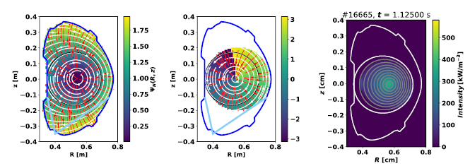
Figure 1. Tomographic procedure for a reduced set of lines of sight. Left: COMPASS vessel with the field of view of AXUV camera F (light blue lines) marked over the  map; center: modified reconstruction domain with preferential smoothing direction parameter—the ratio of
  components with respect to the flux contours; right: typical radiation pattern of an evolved RE beam from the flat-top Ar gas puff scan described further in the text.
Download figure:
Standard image High-resolution image2. Runaway electron beam scenarios
2.1. Ramp-up scenario
COMPASS is characterised by relatively low toroidal magnetic field, which should not be beneficial for the post-disruptive RE beam generation as was shown, e.g., in TEXTOR [24]. On the other hand, RE beams in the ramp-up phase following a classical disruption triggered by massive gas injection (fast thermal quench (TQ), often current spike, current quench (CQ) and beam plateau) were achieved irregularly; see an example discharge in figure 2, where  . The scenario includes a carefully tuned fuelling waveform, injection at early times (low currents/high q95), optimised position reference and argon MGI (see section 1.2 for a description of the valve) at a pressure of 1–3 bar and a short valve opening time. Despite the relatively low reproducibility, a systematic analysis yielded valuable results [10, 11]. Recently the crucial role of the toroidal magnetic field has been confirmed in a dedicated scan [13]. No RE beams were created in the very same scenario at fields lower than 1.1 T, although the beam was reliably produced at higher fields. Based on magnetic measurements and on AXUV inversion and camera data, it is concluded that discharges where Ar MGI does not lead to RE beam generation terminate on the HFS. In contrast, in discharges where a beam is generated following the current quench, the radiation pattern shrinks to the vicinity of the vessel axis during the TQ and CQ [25]. In this case, the low-energy channel of the Cherenkov detector (
 ) indicates the existence of a fast electron population already in the phase of current quench. These beams are often characterised by a very interesting first stage, where bright filaments in the camera images correlate with the short spikes in the ECE and Mirnov coil data and later also in the HXR and Cherenkov detector data [26]. Typically, the generated RE beams are radially unstable—the instability is more severe in the case of a smaller beam current, i.e. a larger drop of current during the current quench. Well confined beams increase their major radius and are lost to the LFS, or partially lost and then stabilised as in the case of the discharge in figure 2.
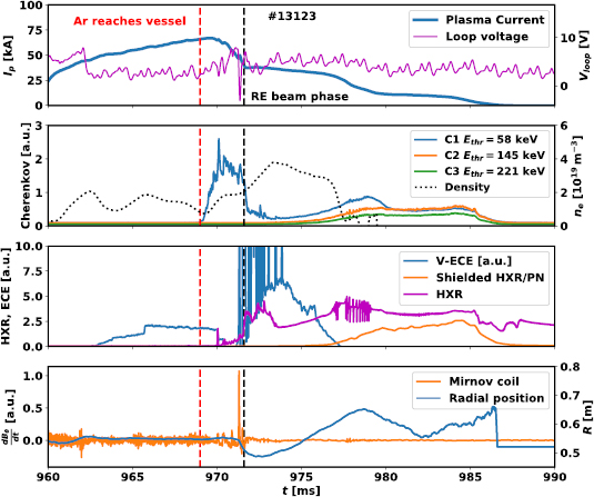
Figure 2. The ramp-up scenario for RE beam generation. Ramp-up of plasma current is interrupted by Ar MGI, which leads to a current quench and RE generation. The density (black dashed line) increases, and the early beam phase is accompanied by spikes in the ECE data and an increased level of HXR. Later the signals of higher-energy Cherenkov detector channels and the shielded HXR detector increase as well.
Download figure:
Standard image High-resolution image2.2. Flat-top scenario
Due to the low reproducibility of the ramp-up scenario, which would be problematic in RE beam decay experiments and scans, an alternative, more quiescent scenario was developed. In these discharges, the current flat-top is reached and the fuelling is turned off, which leads to a decay of the thermal plasma density and a rise of the RE current fraction in several tens of milliseconds. Ar or Ne injection is then introduced using a piezoelectric gas puff or MGI (see section 1.2). MGI causes a significantly faster decay of the RE current, see [13]. During a short delay (5 ms) after the injection, when the gas fills the poloidal cross section, the derivative of the current in the primary windings (which creates the external loop voltage) is set to zero; see figure 3 for a detailed overview. During this stage, additional puffs or RMPs [13, 14] may be applied to investigate the influence on the decay of the beam. The puff causes the quench of the thermal plasma, while the REs are preserved almost unaffected and fully overtake the remaining current. The TQ is very slow in the case of a piezoelectric gas puff, lasting roughly 5 ms (see the evolution of the profile  in figure 4), while it lasts less than 1 ms in the case of MGI. The amount and duration of the gas injection play a crucial role. While this scenario works reliably with the piezoelectric valve injection (slow TQ) at almost any time during the low-density discharge, including the late phase of the ramp-up, the MGI typically causes an immediate current quench when injected too early, while RE beam generation and gradual beam decay are the result of a later injection; see figure 4. This indicates that the slower TQ allows a sufficient RE energy and/or current to be reached during the injection itself, while the fast MGI may only preserve the beam in the case when the RE population is already well evolved. All the results described further in this article are based on this scenario.
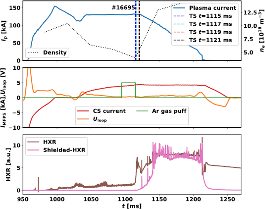
Figure 3. The flat-top scenario with RE beam generation. Top: time evolution of plasma current (blue) and electron density measured by TS (black dotted line); center: loop voltage  (orange), current in the primary windings (red) and Ar gas puff opening (green); bottom: HXR detector signals (brown: >50 keV, pink: >500 keV).
Download figure:
Standard image High-resolution image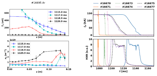
Figure 4. Left: profiles of temperature and density from the TS diagnostics measured at times indicated in figure 3. Right: the timing scan with MGI Ar injection shows that sufficient RE seed or sufficient RE energy is needed for creation and slow termination of an RE beam.
Download figure:
Standard image High-resolution imageAdvantages and possible applications of the flat-top scenario include:
- Reproducible conditions—suitable for scans (e.g.
 , B, RMP effects, etc).
 - Natural or controlled current decay of the RE beam.
- Average RE energy can be modified by timing or prescribed waveforms.
- Optimisation of position control algorithms.
- Validation of models or elements of models that include the RE interaction with impurities (e.g. CODE [27, 28]).
- Investigation of the RE transport in perturbed fields.
- Exploitation of diagnostic methods under well controlled conditions.
- Measurements of RE–wall or RE–limiter interactions during forced terminations.
- Analysis of mutual interaction of REs with various instabilities.


3. Position stability of the runaway electron beam and analogies with a plasma-assisted modified betatron
3.1. Current control
The current of the RE beam on COMPASS can be partly controlled in the case of impurity injections using a low amount of Ar or Ne (piezoelectric valve injection). However, the simultaneous control of radial position and beam current proved to be difficult. When the external loop voltage is removed, the beam current decreases with an average rate related to the type and amount of injected gas(es) [23] and the beam slowly drifts to the low-field side. The application of a feedback control on the plasma current at values above 100 kA requires loop voltage up to 2–4 V and the radial position is driven unstable. However, the beam current was successfully sustained when the current set-point was decreased; see figure 5, discharge  , blue line. The current is typically related to the number of runaway electrons because the change in velocity is small for further accelerated relativistic electrons. Therefore, sustaining the RE beam current in the cold plasma background means compensating for the loss of particles by creating new REs. However, due to the high loop voltage, the energy of confined REs is further increased. This can be clearly seen in figure 5, where the external vertical magnetic field
  based on current flowing in the LFS poloidal coils [29] is indicated: although a constant beam current is maintained, the vertical field necessary to sustain the radial position increases up to very large values (over 100 mT). Moreover, the effect of an ongoing increase in kinetic energy of REs occurs also in the case of spontaneously decaying current, e.g. in discharge
  in figure 3, where zero external loop voltage was applied. The loop voltage induced by the current decay might not be sufficient for primary RE generation but it is sufficient for further acceleration of existing confined REs. Therefore, the position is unstable also during this type of discharge.
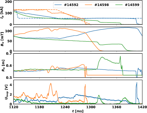
Figure 5. Different attempts to control the current of the runaway electron beam. First frame: measured current and feedback reference (dashed)—in the case of discharge  , zero loop voltage is requested; second frame: total external vertical field—approximate value at R0; third frame: radial position of the plasma current centroid; bottom frame: loop voltage measured on the HFS. In the discharges
  and
and  , deuterium was injected during the RE beam phase (1120–1220 ms) [13], which led to a slower natural current decay.
Download figure:
Standard image High-resolution image3.2. Radial stability of the relativistic electron beam and the role of RE energy
The runaway orbits in equilibrium magnetic field and even the contribution of the runaway current to the total equilibrium have been studied in many publications, including [30, 31]. In present devices, the policy on radial position feedback during the RE beam stage is often modified based on empirical results and adaptive control (see [6, 32]) because the physical model of this situation turns out to be rather complicated. The radial stability of the RE beam is incompatible with the standard feedback scheme applied on COMPASS and must be modified. The radial position on COMPASS is actuated by two different systems—equilibrium field power supply (EFPS) and fast vertical magnetic field power supply (FABV) [33]. The controller of the first one contains a term proportional to the plasma current (as a result of the Grad–Shafranov equilibrium, see equation (2)) and proportional–integral terms of the radial position error of the current centroid with respect to the reference. The FABV is dependent only on the position error and is also approximately five times weaker in maximum amplitude than EFPS. The system performs excellently in the case of a high-temperature plasma without RE; however, the performance is poor with an RE beam in the low-temperature plasma background, as can be seen in figure 6. In the figure, various scenarios are compared in terms of evolution of plasma current, normalised value of current in the EFPS windings ( —the constant is added so the function is stable when approaching zero), radial position and loop voltage that drives the current in plasma or accelerates the runaway electrons. It is obvious that while the value of the function in the second frame is constant in the case displayed using a green dotted line (standard discharge), this quantity is quickly increasing in the case of various RE scenarios: RE beams triggered by MGI (
 —thick orange line) or piezoelectric valve Ar gas injection with plasma current feedback (
 —violet line) or zero loop voltage applied (
 —blue line,
  —red dashed line + additional D injection added). The faster the current decay of the RE-dominated plasma or loop voltage, the higher the request for the vertical field normalised by the plasma current value due to a higher loop voltage induced during the current decay and a subsequent increase in RE energy. Notice that despite large values of current in the stabilising windings the beam still drifts to the LFS. From this observation it is obvious that the dependence of radial feedback on plasma current is too strong. The standard tokamak request for a vertical field that results from the Grad–Shafranov equation can be expressed as [34]
where the first term on the right-hand side is related to external and internal parts of the 'hoop force' (force between the current elements within the plasma ring), the second term (with  ) to the 'tire tube force', i.e. expansion due to the kinetic pressure gradient, and the
  term changes the direction with the value of
  . The terms—except the
  contribution—are always outward and typically depend on plasma current squared (the pressure term via the
  value). This means that vertical magnetic field should also be dependent on
  . If we consider the case of the runaway electron beam, the hoop force terms should still be valid but the current density profile and therefore the internal inductance of the beam might be very different compared to thermal plasma. However, the gradient of classical thermal pressure is practically negligible for a low-temperature plasma background that may even have a large neutral fraction. Therefore, the dependence of vertical field on current in the beam ring should be weaker in the case of REs. Note that the size of the beam in terms of minor radius may also affect the feedback efficiency.

Figure 6. Comparison of radial control performance in the standard discharge (green) and various RE beam scenarios: Ar injection by MGI ( ), piezo valve injection (
 ) or Ar injection followed by D injection (1120–1220 ms,
  ,
,  ). The first frame shows the evolution of plasma current and color-coded rectangles marking the opening time of the gas injection valves; MGI is marked by a black outline. The second frame shows that the current requested from external poloidal field coils for radial position control is not a function of
  only in case of the RE beam. The third frame displays the evolution of radial position, the fourth shows the loop voltage values and the last one the signal from the shielded HXR detector.
Download figure:
Standard image High-resolution image3.3. Radial stabilisation of the RE beam
A comparison of RE beams in a tokamak with those in high-current betatrons—specifically the modified ones (including the toroidal stabilising field) [35]—turns out to be appropriate. The average energy of a beam of electrons plays a crucial role in determining the  value necessary to keep the beam particles on radially stable orbits. If the Larmor radius in a vertical magnetic field is considered (which applies in the case of a low beam current), the vertical field should be proportional to the change in flux or the average kinetic energy
  of the accelerated electrons as in the classical betatron. The value of the vertical field necessary to confine a high-current RE beam in the tokamak should be proportional to the sum of this contribution and the hoop force compensation:
in the ultra-relativistic case. Based on the theory for plasma-assisted modified betatrons, the beam in the plasma background should always be paramagnetic, unlike in the vacuum variant of the modified betatron, where a diamagnetic to paramagnetic transition occurs during the acceleration of a high-current beam according to conditions indicated in [35]. The paramagnetism is responsible for an additional confining force. In order to achieve a suitable feedback policy it is often sufficient to simply decrease the relative contribution of the part proportional to  with respect to the contribution of term due to radial position error in the controller. Most tokamaks are close to the situation where the
  term—based primarily on
  —is close to optimum for the given major radius and energies of REs in the range of tens of MeV. On COMPASS, as a small device, the beam is typically drifting to the LFS in the quiescent stage, while overestimated vertical field may push the RE beam to the HFS or cause position oscillations in the case of loss of some part of the current—see discharge
  in figure 6. Standard feedback with decreased
  dependence may perform sufficiently well, but equation (2) or a more complex model taking the average runaway electron energy into account should increase the efficiency of the feedback. On the other hand, the feedback algorithm disturbed in a controlled way may be a source of information on the average energy of REs in the beam or even on the range of the energies. To investigate whether information on the change in flux (electric field integral) is useful for estimating the optimal vertical field for radial position feedback, the discharge
  can be further analysed. Let us assume that at the beginning of the 50 kA RE beam plateau (240 ms after the breakdown), the total requested vertical field is balancing well both the 'hoop force' and the relativistic pressure arising from the change in energy. If only the second part of equation (2) were taken into account (low-current betatron approximation), the energy corresponding to the applied vertical field would be roughly 10–11 MeV at the beginning of the constant-current phase. This is in a reasonable agreement with other methods of determination of the upper energy limit for REs originating from the breakdown in various COMPASS discharges:
- Non-collimated HXR spectrometry shows that the energy limit of HXR reliably measurable with the crystal (7 MeV) is reached after approximately 150 ms of acceleration of REs in the COMPASS standard discharge with a trace RE population. This measurement is unfortunately not available directly for the studied discharge due to extremely large HXR fluxes.
- Measurements of synchrotron radiation using a camera in the mid-IR range (15–25 m) placed at a suitable tangential port show the start of an increase in the measured power due to synchrotron radiation roughly 190 ms after the breakdown. This measurement is also an approximation because it is measured in a low-density discharge without gas injection. Based on the synchrotron radiation model SYRUP [36] using the single-energy approximation, only electrons with energy higher than 8–10 MeV give a non-negligible contribution in the spectral sensitivity range of the camera and the COMPASS magnetic field ().
- Last but not least, the energy calculated using the vacuum acceleration approximation based on the loop voltage measured at the HFS reaches roughly 20 MeV at the point of the start of the RE beam plateau in discharge . The vacuum approximation provides overestimated values in general.


From the start of the constant-current request phase, the beam current is stable, but the radial distribution of the current density might be changing and there is definitely a change in energy. In figure 7, it can be seen that the increase in applied vertical field is proportional to the evolution of electric field through the relation marked in the legend of the graph; however, a decreased value of the field derived from loop voltage measurement must be used in order to get a complete fit. This may result from the drag force due to impurities, imprecision of electric field measurement (loop external to the vessel) or other effects such as a change in the RE density profile and the RE energy distribution along the minor radius.
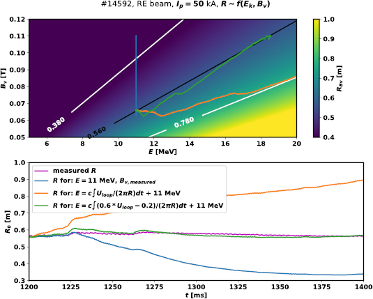
Figure 7. Top: 2D plane with ultra-relativistic electron Larmor radius as a function of energy and vertical field with curves of calculated  for the signals of discharge
  . Bottom: comparison of measured radial position signal and hypothetical position corresponding to
  evolution and energies obtained using different functions of electric field as marked in the legend.
Download figure:
Standard image High-resolution image3.4. MHD equilibrium approximation for the RE beam
The description mentioned above as a first approach is based on rather simplistic assumptions. A more suitable approach to the RE beam feedback is to use relativistic pressure. This was applied in the calculation of RE current fraction in thermal plasma in [37] and more recently in [38]. In this case, it is suitable to use the relativistic pressure formula given by the equation [37]
where the RE density  is averaged over beam volume and the velocity squared times Lorentz factor
  over both spatial and velocity distributions. Assuming that the relativistic pressure gradient is given primarily by the density gradient—rather than by the change in the average energy with the radius—the gradient of the RE pressure can be approximated by
where  is the beam minor radius. However, the effect of the radial profile of the average energy needs to be included as well to fully reconstruct the possible equilibria. The relativistic pressure gradient can be used in the MHD equilibrium
  and modified equilibrium can be found. This introduces an additional component of vertical field. The measured electric field integral or evolution of electric field as an output of a benchmarked disruption model seems to be a suitable input for a physics-based proportional controller of radial position in the case of a relativistic beam. Such an approach may further increase the performance of the well performing adaptive control algorithms currently run on medium sized devices. The relations will be tested on COMPASS during future RE experiments.
3.5. Vertical stability
To investigate the vertical stability of the RE beam created using the flat-top recipe with Ar, a scan in the amplitude of the elongating field was carried out. It seems that the generation of the RE beam by a mitigation of the thermal plasma component via gas injection is not significantly affected by plasma elongation. As expected, the beam is prone to a vertical instability during the decay of its current, and the instability occurs earlier for a higher elongating field—this is reported in figure 8. It seems that at the highest value of the elongation requested in the scan ( ) it is more difficult for the control system to sustain the current during the injection, and slightly higher
  is requested. The vertical displacement events last several milliseconds and are characterised by large spikes in loop voltage.
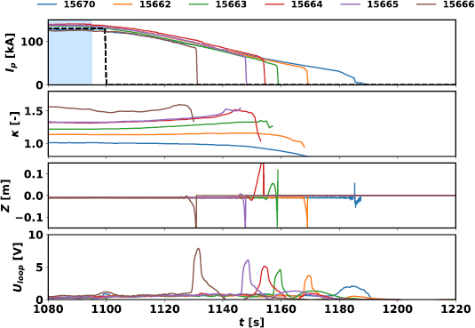
Figure 8. Elongation scan with piezoelectric gas puff Ar injection (1075–1095 ms). First frame: evolution of RE beam current in the regime of zero external loop voltage (common reference—black dashed line, elongation increased with the discharge number); second frame: elongation as calculated by EFIT; third frame: measured vertical position; last frame: measured  .
.
Download figure:
Standard image High-resolution image4. Decay rate and energy loss channels
The beam energy (magnetic and kinetic) can be lost through several channels—direct particle loss, radiation due to decay of excited atomic states of the background plasma species, induced currents in the vessel structures due to loss of the beam current, etc. Based on the scans of gas amount with Ar and Ne, it seems that the two gases behave very differently in terms of the beam energy loss channels—while the RE beam in Ne radiates with larger power in the AXUV spectral region, Ar causes a larger averaged signal of the  neutron counter and photomultiplier-based detector measuring high HXR fluxes during the beam decay while other HXR detectors are already saturated; see figure 9. Note that the
  neutron counter can also be affected by the HXR if the fluxes are too large. The radiated power was calculated using the modified tomography algorithm presented in section 1.3. More Ne is injected and a higher pressure of the injected gas is measured if the same setup of valves is used for the given pressure—the gas is lighter and therefore moving faster both during the expansion into the vacuum and in the supply tubes. However, the current decay rate of the RE beam is comparable for both gases with the same gas injection setup (see figure 3 in [13], discharges with various amount of injected Ar or Ne particles) and therefore the effect of the gases on the two energy loss channels can be directly compared. Their relation may be a useful argument to prefer one gas over the other for different tasks. Argon seems to be a better choice to cause fast scattering of REs as a last layer of defence. On the other hand, if the RE beam position is stable and controlled, injecting large amounts of Ne can terminate the RE beam in a significantly more quiescent manner with a large fraction of the energy being radiated in the visible, UV and SXR spectral regions.

Figure 9. Scans of gas amount for Ar and Ne, quantities plotted with respect to the average current decay rate of the RE beam: (a) the average radiated power during the beam decay calculated using AXUV tomography; (b) maximum AXUV radiated power during the beam decay; (c) number of counts of the  neutron detector (HXRs and photoneturons) normalised to duration of beam decay; (d) average HXR as measured by a blind photomultiplier during the beam decay.
Download figure:
Standard image High-resolution image
5. Conclusions
Experiments using two different scenarios with RE beam generation triggered by gas injection are under investigation at COMPASS: the ramp-up scenario and the flat-top scenario. The former includes typical disruption features such as current quench and is more relevant to larger machines in terms of RE generation. However, the reproducibility and control possibilities were not sufficient in this scenario on COMPASS. Therefore, a flat-top scenario with a high-current RE beam was developed using various amounts of Ar or Ne to isolate the beam from the thermal plasma component. The current of the RE beam generated in this way may be kept at the desired value in the Ar or Ne background plasma at the cost of a relatively high loop voltage. However, it is even more interesting to switch off the external drive and observe the self-consistent decay of the beam. The radial position feedback was not performing very well, possibly due to: (i) the absence of a thermal pressure gradient that would require a vertical magnetic field proportional to beam current and (ii) the role of RE energy missing in the request on the vertical magnetic field that would secure stable orbits. This hypothesis will be tested in the next campaigns. Regarding the vertical position, the elongated RE beam seems to be stable even at relatively high values of elongation, unless the current decreases below a certain threshold. During the RE beam decay, some of the total energy is lost in the interaction with the gas (excitation, ionization and subsequent radiation) or directly through RE loss to the wall. Ar and Ne seem to behave oppositely: while Ar causes more high-energy HXR signal indicating larger RE losses, Ne causes stronger radiation in the AXUV spectral region. The work on this scenario will further continue with the feedback optimization, puffing of gas mixtures, analysis of instabilities and investigation of the influence of magnetic field perturbation in order to provide a large set of reliable results for medium sized and large machines, where safety constraints are more limiting than on COMPASS, and to validate the key elements of runaway electron models.
Acknowledgments
The work has been supported by the grant GA18-02482S of the Czech Science Foundation and also by the grant No. SGS19/180/OHK4/3T/14 of the Grant Agency of the Czech Technical University in Prague. The experiments were supported by project Nos. CZ.02.1.01/0.0/0.0/16_019/0000768 and LM2015045, co-funded from European structural and investment funds and carried out within the framework of the EUROfusion Consortium. The work has also received funding from the Euratom research and training programme 2014–2018 under grant agreement No. 633053 with the Co-fund by the MEYS project number 8D15001. The views and opinions expressed herein do not necessarily reflect those of the European Commission.