

Abstract
In future fusion reactors, the blanket is foreseen to remove heat from the reactor and enclose material to breed tritium. While the blanket structure is made of steel, for a successful operation its first wall (FW) needs to be armoured by a tungsten layer. Joining tungsten and steel is currently a key issue in engineering nuclear fusion reactors beyond ITER as will be shown in this publication. This manuscript firstly presents the influence of the joining procedure on stress and strain fields in the FW. Secondly, general aspects that need to be considered in realizing the joint are introduced and, lastly, an overview of current approaches to realize tungsten-armoured steel is given. A comparison of the challenges and approaches leads to the conclusion that all joining techniques require much more research, and that the field currently suffers from a missing programmatic research approach.
Export citation and abstract BibTeX RIS
1. Introduction
On the pathway to commercial nuclear fusion power plants, the demonstration reactor DEMO will play an important role. It is foreseen that, for the first time in fusion history, a reactor will breed tritium (T) self-sufficiently [1, 2]. Breeding will occur in blanket modules, surrounding the fusion plasma. Tritium and helium-4 are formed by nuclear reactions of lithium and neutrons (n). A successful DEMO breeding blanket removes average heat loads of ∼1 MW m−2 impinging on the blanket surface for the generation of electric energy and sustains a breeding ratio T/n > 1.1 [2]. Sophisticated blanket concepts have been developed, which incorporate neutron multipliers (e.g. Pb and Be) in different conditions, use different cooling media (helium and water), and rely on different geometries. A critical reassessment of the concepts Helium Cooled Pebble Bed (HCPB), Helium Cooled Lithium Lead (HCLL), Water Cooled Lithium Lead (WCLL), and Dual Coolant Lithium Lead (DCLL), studied in the framework of the EUROfusion Work Package Breeding Blanket, has recommended to focus on the HCPB and the WCLL blanket [2]. Overview images of the two strategies are shown in figure 1. Despite significant differences between the HCPB and the WCLL blanket, important similarities exist particularly concerning the first wall (FW), which represents the first few plasma facing millimetres of the blankets. Both breeding concepts rely on a Eurofer steel [3] structure, housing the breeding zone and cooling channels. Eurofer is a ferritic-martensitic steel and represents a low activation version of well-characterized creep-resistant chromium steels. At the FW, Eurofer is covered with a ∼2 mm thick tungsten armour layer [1]. Tungsten is considered the prime plasma facing material due to several reasons, e.g. its high liquidus temperature, high threshold energy for sputtering, low sputter yield, low fuel retention, high thermal conductivity, and moderate activation compared to other fusion relevant materials. Rectangular cooling channels, placed in the steel structure in close proximity to the tungsten armour are foreseen to remove FW surface heat loads. A comparison of geometric boundary conditions, applying to the FW of both breeding concepts similarly, is presented in figure 2 [4, 5].

Figure 1. The generic DEMO blanket (orange part in the top centre) may be represented by the HCPB (bottom right) [4] or the WCLL (bottom left) [6] breeding blanket. Both schematics shown here base on the single module segment approach. Both concepts have a similar first wall.
Download figure:
Standard image High-resolution image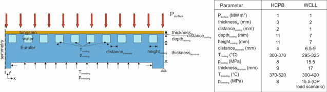
Figure 2. Comparison of important boundary conditions, applying to the FW of the HCPB and the WCLL breeding blanket. HCPB based on [4], WCLL on [5, 7, 8].
Download figure:
Standard image High-resolution imageIn order to tackle challenges regarding the tungsten-steel joint of both concepts, this publication first focusses on the evolution and distribution of joining-related stresses and strains in the FW. This is shown exemplarily for a WCLL-like part. Partially based on the finite element (FE) results, general considerations required for FW joints are then summarized, followed by a detailed overview of current approaches to join tungsten and steel. A conclusion is finally drawn, based on the aforementioned analyses.
2. FE model
In modelling studies of blankets, the boundary conditions presented in figure 2 show adequate performances with tritium breeding ratios >1.1 and acceptable heat removal capabilities. Unfortunately, studies on both blanket concepts show that a criterion against plastic flow localization is not fulfilled all over the HCPB [9] and the WCLL blanket [7, 8]. On one hand, castellation of the tungsten armour easing the stress profile was not yet considered in these studies. But on the other hand, also material degradation (e.g. embrittlement), interface imperfections and residual stresses from fabricating the FW were not taken into account. Residual stresses are important, because no matter which joining technique is selected, joining tungsten and steel occurs at elevated temperatures, which represents the joint's actual stress-free condition. Upon cooling, residual stresses are thermally induced due to strongly differing coefficients of thermal expansion (CTE) of tungsten and steel (4.4 × 10⁻⁶ and 12.0 × 10⁻⁶  at room temperature). As will be shown in section 4, joining is either carried out at temperatures well above the α–γ transition temperature of Eurofer (Tα−γ ≈ 800 °C), or at ∼700 °C. In case of the former, usually a post-bonding heat treatment (PBHT: normalization at ∼950 °C for 0.5–1 h, fast cooling, and tempering at 760 °C for 90 min [10]) is added to regain the martensitic Eurofer steel microstructure. The normalization step during PBHT should remove a large amount of formerly induced residual stresses. Hence, two stress-free temperatures, ∼700 °C and ∼950 °C, may be interesting for modelling joining.
An exemplary FE model of an excerpt of the WCLL FW shows how fabrication-related residual stresses affect the stresses and plastic strains in the component during early stages of its lifetime. The boundary conditions applied here refer to figure 2, only the tungsten layer of the FE model is slightly thicker (2.5 mm). For the 2D model, a plane strain environment is assumed to account for the large joint area of not-castellated tungsten and steel. Temperature-dependent mechanical and thermo-physical material properties of Eurofer and tungsten were applied based on [3, 11]. An elastic-ideal plastic material behaviour was considered. Viscoplastic behaviour was neglected. Six different load steps were modelled:
- 1.Initial condition
- Case (a): stress-free joint at room temperature (as assumed by most FE breeding blanket models) resting for 100 s.
- Case (b): cooling from stress-free joining temperature (700 °C) to room temperature within 100 s.
- 2.Implementation of the blanket in the reactor, represented by raising the cooling temperature and pressure, and breeding temperature and pressure on the edges indicated in figure 2 (a virtual time of 1 h was assumed for this step).
- 3.Ignition of the plasma, represented by raising a DEMO-relevant heat load of 1 MW m−2 on the edge indicated in figure 2 within 100 s.
- 4.Steady-state operation of 2 h at full heat load, and constant cooling and breeding conditions.
- 5.End of DEMO pulse, represented by reducing the plasma heat load to 0 W m−2 within 100 s.
- 6.Down-time (1 h) of DEMO, only loads from the cooling and breeding temperature and pressure are applied during that step in the model.
To consider pulsed operation of DEMO in the model, the beginning of a second DEMO load cycle is simulated after the down-time (load steps 3' and 4'). Figure 3 shows the maximum temperature and stresses in the entire structure over time for cases (a) and (b). The different load steps are clearly distinguishable. After step 1, in case (a), the model is stress-free. In contrast, the same step in case (b) (cooling to room temperature) shows the development of significant stresses and plastic strain. The von Mises stress maximum reaches 1359 MPa, σyy stresses reach 1103 MPa. According to figure 4, the stress distribution at the end of step 1 in case (b) at room temperature is inhomogeneous, with the σyy stress maximum existing at the circumference of the tungsten-Eurofer boundary. The von Mises maximum is located within the component and mainly bases on compression. It is hence considered less severe than the σyy stress maximum, which requires unrealistically high adhesion strength of the joint (>1100 MPa, i.e. two times the Eurofer yield strength). Under realistic conditions, σyy stresses in the present model will cause debonding of the joint. Since debonding was excluded in the model, severe plastic deformation occurs in the part. It should be noted that the current WCLL design foresees to wrap the FW around the whole blanket modules toroidally and does not contain as many free tungsten-Eurofer edges close to the plasma as indicated by the presented model. However, since the stress intensity at the tungsten-steel joint scales with the joint area [12], castellation of the FW is likely required to limit stresses. This will result in the presented σyy stress distribution, indicating very small castellation is required.

Figure 3. Evolution of temperature, von Mises stresses, σyy stresses, and accumulated plastic strain over time in the modelled FW component. Case (a) (start at room temperature (RT)) is depicted in solid lines and case (b) (start at 700 °C) in dashed lines.
Download figure:
Standard image High-resolution image
Figure 4. Contour plots of von Mises stresses, σyy stresses, and accumulated plastic strain in the top right corner of the modelled component after cooling to room temperature (100 s). The arrows indicate positions of maxima.
Download figure:
Standard image High-resolution imageStresses causing the described deformations after cooling from joining temperature are in fact higher than stresses during (the first) DEMO heat pulse as can be seen from the von Mises stress versus time evolution in figure 3. Comparing cases (a) and (b) in this figure, the behaviour of stress increase and decrease are inverse for the two cases. Based on that, the impression may be created that models, which assume room temperature as the stress-free condition, actually overestimate stresses during DEMO heat pulses. However, this impression is only true if no plastic deformation occurs during cooling from joining temperature. For the presented model, in case (a), σyy stresses during heat pulses are actually underestimated due to localized plastic deformations, instead of being overestimated.
The presented results have implications both on the FE modelling of blankets and on the experimental joining of tungsten and steel. With respect to modelling, the consideration or negligence of fabrication-related residual stresses influences the failure criteria of plasma-facing tungsten-steel joints that were identified by thermal-structural FE analyses in the past, e.g. in [9, 13–18]. Among the failure mechanisms are (i) exceedance of the upper and lower temperature limits of used materials, (ii) spontaneous failure due to stresses exceeding ultimate strengths, (iii) debonding of the tungsten-Eurofer joint, (iv) creep failure of Eurofer, (v) thermo-mechanical fatigue. Although it remains unclear to date how the actual joining of tungsten and steel will be realized, neglecting any fabrication-related stresses in FE modelling might substantially underestimate the onset of localized plastification or debonding in the FW. With regard to experiments, the stress profile explains why many joints fail at the tungsten side of the joint. Here, the σyy stresses are maximal. The extent of these stresses in general depends on the geometry of the joined tungsten and steel parts. Hence, comparable joint geometries are required for benchmarking different bonding techniques.
3. General considerations for FW joints
In section 2, the impact of fabrication-related residual stresses on tungsten-steel joints of the FW and potential failure mechanisms were presented. In order to best cope with these challenges, several joining concepts have been developed. They all have to fulfil general boundary conditions, summarized in figure 5 and explained in the following.
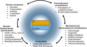
Figure 5. General aspects, required for consideration of FW joints.
Download figure:
Standard image High-resolution imageWith regard to nuclear constraints, particularly important if interlayers are used to join tungsten and steel, only those elements should be used, whose dose rate decreases below the shielded hands-on level of 2 mSv h−1 within 100 years after irradiation and reactor shut-down (exemplary reactor scenario: 1.6 GW thermal power, neutron flux density 5.04 × 1014 cm−2 s−1, 2 years reactor operation [19]). This is important for possible remote-handled recycling of the used materials in a new generation of reactors by the time. Moreover, no transmutation of elements to helium or long-living radionuclides during application in DEMO is allowed. A large tritium breeding ratio asks for low neutron capture in the FW, which has to be considered both in terms of material selection and geometric constraints. Besides that, a general trade-off between plasma erosion of the tungsten armour limiting the FW lifetime, neutron transmittance, thermal capabilities and mechanical integrity of the FW has to be found. In the long-term, neutron and possibly hydrogen induced embrittlement of used materials is to be considered.
As for mechanical properties of the FW, all materials used require high yield strengths at room temperature and at elevated temperatures. If joining is carried out at temperatures above the α–γ transition temperature of Eurofer (∼800 °C), a PBHT is required to re-establish the martensitic steel structure. The thermo-mechanical FE analysis presented in section 2 shows that high σyy normal stresses impose on the joint after cooling from joining temperature. The adhesion strength of the FW joint has to be high enough to cope with these stresses. Apart from that, FE analyses showed that the joint experiences cyclic thermo-mechanical loading. Hence, the joint has to be protected against ratcheting, which might cause fatigue failure eventually [9]. While the von Mises stresses during heat pulses are lower than at room temperature, they are still critical, especially since materials usually soften at elevated temperatures. The aspect demands for acceptable creep strength of the materials used in the joint. Additionally, in case of overloading, failure must not occur spontaneously. Given this prerequisite, toughness of the joint and used materials at elevated temperatures has to be ensured.
With respect to thermo-physical considerations, one main task of the FW is to remove heat. Hence, materials and interfaces have to provide a high thermal conductivity. Related to the aspect of stress distribution, potentially used interlayers should exhibit a coefficient of thermal expansion in the range of tungsten and Eurofer (4.4 × 10⁻⁶ and 12.0 × 10⁻⁶  at room temperature), if they are thicker than few micrometres, which is likely needed.
In order to fulfil its duties durably, a thermodynamically stable materials combination has to be chosen for the FW. The localized precipitation of hard particles, particularly at dissimilar materials interfaces, after long-term exposure to elevated temperatures might cause stress intensities and provide low-energy crack paths. Apart from that, for Eurofer, diffusion of carbon towards the joint, accompanied by ferritization of the microstructure and loss of strength, and the α–γ transition temperature, mentioned above, need to be considered for joining.
Some general boundary conditions for the FW arise by the selection of the breeding blanket concept. The size of a continuous tungsten-steel joint, which depends on the outer geometry of the blanket and on potential castellation of the FW, will influence the stress profile as much as the selection of cooling medium (temperature and pressure) and breeding concept (also temperature and pressure) will.
Eventually, given the proposed FW area of 1200 m2 in the EU DEMO 2015 baseline design [2], a high throughput in joining tungsten and steel should be achievable, e.g. by joining large areas at once, by mass-producing small joint areas, or by other attempts. Over the lifetime of the FW, the mean time between failure and the mean time to repair will be decisive parameters, asking for enduring joints that allow fast and reliable repair in case of failure [20].
Of course, most of the named considerations interact with others, i.e. changing one boundary condition will inevitably affect others. With respect to this, the suggested considerations are not meant to be complete. Particularly regarding very short and long time-scales more aspects become important.
4. Approaches to join tungsten and steel
Joining tungsten and steel has been studied for both divertor and FW applications. In the following, actual applications are neglected and only the joining techniques are compared. Given the wide variety of techniques and materials used for joining tungsten and steel, an overview requires a consistent nomenclature. Hence, in the following
- Elements or materials separated by '-' (e.g. 'W-steel') describe a joint of two discrete layers of the two materials, in the example tungsten and steel.
- Elements written consecutively (e.g. 'FeW') describe a not further defined mixture of these elements on the atomic level, e.g. a solid solution or when the condition is not provided in detail in literature.
- Elements written consecutively with subscripts (e.g. FexWy) indicate particular phases observed, e.g. in the form of
 precipitates in a FeW layer.
 - Elements or materials separated by '/' (e.g. 'W/steel') describe a mixture of these materials on the microscopic level, e.g. a metal matrix composite (MMC).

4.1. Direct solid state bonding
Joining bulk tungsten and bulk steel directly is a reasonable start for joining experiments, because established processing techniques can be used, only one joining step is carried out (and maybe one PBHT), only one dissimilar materials interface is present, and no materials other than the base materials are required, which helps with nuclear considerations. Solid state bonding techniques, such as uniaxial diffusion bonding (DB) and spark plasma sintering (SPS), have been carried out at 1050 °C, 960 °C, and 800 °C for 0.5–4 h at uniaxial pressures between 15 and 60 MPa, causing approximately 8% creep in the steel part to ensure proper bonding [21–24]. To date, joining tungsten and steel directly has not been successful with any of the suggested techniques and parameters. Combinations of high joining temperatures and long bonding durations result in joints of high as-joint ultimate tensile strength (∼450 MPa) at 650 °C, but due to exceedance of the α–γ transition during joining, Eurofer is not martensitic any more. PBHT causes high residual stresses, so that the joint breaks easily during cross section preparation [23]. This observation conforms to the results of the FE analysis of section 2. Apart from that, brittle intermetallics and carbides precipitate at the direct interface of tungsten and Eurofer [21, 23]. Successful direct joining of tungsten and steel at temperatures below the Eurofer α–γ transition temperature has not been reported, creep seems to be too low here for proper bonding.
4.2. Solid state bonding with discrete interlayers
Resulting from the unsuccessful direct solid state bonding of tungsten and steel, a variety of attempts use discrete interlayers in the joint. In several publications, the insertion of 1 mm thick vanadium layers between the tungsten and steel parts has been investigated [24–28]. Vanadium is a reasonable candidate because it shows a comparably fast decline of the shut-down dose rate after exposure to a DEMO relevant neutron spectrum [19] and offers a CTE between the one of Eurofer and tungsten (8.4 × 10⁻⁶  at room temperature). Joining has been carried out at 1050 °C, 800 °C, and 700 °C for 1–4 h at uniaxial pressures corresponding to ∼10% creep at the Eurofer side of the joint. According to [27], at 700 °C, this corresponds to approximately 97 MPa bonding pressure. The outcome of this strategy seems promising, particularly when joining at low temperatures (700 °C) and long durations (4 h). No cracks are apparent, and in comparison to higher DB temperatures, this combination forms no FeV intermetallics and only a very thin VC layer (1 μm) at the vanadium-Eurofer interface. At room temperature, the joint exhibits a yield strength of ∼320 MPa and ultimate tensile strength of ∼330 MPa with low elongation at fracture. At 550 °C, yield and ultimate strength decrease by 25% and 12%, but the elongation increases drastically due to plastic deformation of vanadium. The location of fracture depends on the processing conditions and test temperature, and is described in detail elsewhere [27, 28]. Room temperature shear tests, Charpy impact tests at 550 °C, and thermal fatigue tests were carried out, too, proving a shear strength of 200 MPa, absorbed impact energy of 2 J and the endurance of 100 cycles between 350 °C and 500 °C in a vacuum furnace, respectively. After thermal fatigue testing, which took about 130 h, the VC layer increased slightly with some decarburization of Eurofer.
DB has also been carried out with the aid of a 1 mm thick niobium interlayer at 1050 °C for 1 h at uniaxial pressures causing ∼8% creep in Eurofer, with the typical PBHT [29]. Although initial experiments showed reasonable results, the strategy was terminated, probably owing to the excessive activation of niobium during DEMO relevant neutron exposure [19]. Similar to vanadium, niobium is a strong carbide former potentially decarburizing Eurofer.
Another discrete interlayer option, studied in many publications, is titanium. The activation of titanium is acceptable and the CTE equals 8.6 × 10⁻⁶  at room temperature. Joining has been carried out by pulse plasma sintering [30], DB [31, 32], and hot isostatic pressing (HIP) [33–38]. While the Ti interlayer used for pulse plasma sintering was rather thick (1 mm), it varied between 0.1 and 0.6 mm for DB, and between only 0.03 and 0.5 mm for HIP. The joining with pulse plasma sintering was carried out at 1000 °C. Required pressure and time are not provided. DB takes place at 950 °C for 0.5–1 h at 10–15 MPa uniaxial pressure. In contrast, for HIP, the (isostatic) pressure is strongly increased to 100 MPa, where joining is usually done at 900 °C for 1.5 h and combined with a second heat treatment (750 °C, 2 h, 70 MPa). Only two HIP joints have been realized at a temperature (760 °C) below the Eurofer α–γ transition, using higher stresses (150 MPa) and longer joining durations (4 h) [37, 38]. Despite processing differences, some commonalities are found among the aforementioned studies. Except for the pulse plasma sintered joints, no study reports the existence of cracks. In terms of microstructural changes, in [30, 38] the diffusion of iron to titanium is reported, and in [35, 36] the decarburization and ferritization of steel at the Ti-steel interface. After extended joining under high pressure, interdiffusion of titanium and tungsten is observed [37]. Mechanical test results are limited for this type of joint. The shear strength of titanium joints, HIPed at 950 °C and subsequently heat-treated, reaches 89 MPa with intergranular failure in the tungsten part [35]. HIPing at 760 °C yields shear strengths of 50–65 MPa with failure at the Ti-steel interface [38]. After annealing at 700 °C for 5 h, the shear strength increases to 120–130 MPa [38]. An interesting aspect for all types of tungsten-steel joints, which has only been assessed for HIPed Ti joints is the impact of
  on the joint. Depending on the
  partial pressure, the shear strength of the joint decreases dramatically, and at 1 bar
  the titanium interlayer turns into
  powder.
Other, less commonly used interlayers are pure iron, pulse plasma sintered at 700 °C and at 1000 °C [30, 39], FeTi [30], and NiFe [40].
4.3. Brazing with and without additional discrete interlayers
Compared to solid state bonding, from a technological standpoint brazing is preferable. No external force is required and the joining of curved surfaces is easier because the liquid braze is tailored to penetrate the parent materials and spreads well.
A large number of high temperature brazing techniques, listed in table 1, has been developed. A dedicated comparison and evaluation is challenging, given significant differences regarding the used brazes, layer thickness, and processing steps. Independent from these differences, brazing tungsten and steel is usually carried out above the Eurofer α–γ transition temperature, at 950 °C–1100 °C, in vacuum furnaces. Some techniques are carried out in flowing argon atmosphere, further facilitating the processes [41–43]. Despite high joining temperatures used, usually no PBHT is carried out to re-establish the original ferritic-martensitic microstructure of Eurofer, although the need is described in [44–47], where it has been done. Altered Eurofer microstructures and mechanical properties should be considered after brazing, if PBHT is neglected. Usually, the braze layers have a low thickness (15–200 μm), which does not allow to account for the mismatch of CTE of tungsten and steel. Hence, some attempts make use of additional interlayers to the braze, consisting of e.g. Cu [26, 41–43, 48], V base alloys [45–47], or Ti [49]. For these interlayers, the same boundary conditions like for indirect solid state bonding have to be fulfilled. With regard to that, the large CTE, low strength and low liqidus temperature of copper used in some braze joints may cause challenges during cyclic high-temperature application. Compared to solid state bonding, with brazing, large reaction layers, often composing of secondary phases, are formed at interfaces already during joining and the reaction layers are decisive for the performance of the joint. While the layers are supposed to enhance the bond between adjacent materials, they are sometimes intrinsically brittle and weak, hence representing the weak spot of the joint. Detailed information about the observed microstructures after brazing may be found in the literature of table 1.
Table 1. Overview of several brazing concepts carried out to join tungsten and steel. Additionally to the braze, some concepts named here make use of filler layers to relieve stresses.
| Braze | Layers of different materials in the joint | Brazing temperature and time |
|---|---|---|
| Ni [26, 41–43, 48] | W—20 μm Ni—200 μm Cu—20 μm Ni—Eurofer | ∼1100 °C–1150 °C, ∼10 min |
| Pd [41–43] | W—15 μm Pd—80 μm Cu—15 μm Pd—W | ∼1100 °C, ∼10 min |
| AuCuFe [50] | W—50 μm AuCuFe—Eurofer | ∼1000 °C, ∼5 min |
| CuTi [51–54] | W—150 μm CuTi—Eurofer | ∼950 °C, 1–10 min |
| CuTi [45] | W—50 μm CuTi—Rusfer | ∼980 °C, ∼30 min |
| CuTi [45] | W—50 μm CuTi—1 mm VTiCr—50 μm CuTi—Rusfer | ∼980 °C, ∼30 min |
| CuGe [45] | W—50 μm CuGe—1 mm VTiCr—50 μm CuGe—Rusfer | ∼800 °C, ∼20 min |
| Cu [46] | W—100 μm Cu—Rusfer | ∼1100 °C, ∼20 min |
| FeBSi [55] | W—10 μm FeBSi—ODS ferritic steel | ∼1180 °C, ∼240 min |
| FeBCrSi [47] | W—30 μm FeBCrSi—150 μm V—30 μm FeBCrSi—CLF-1 | ∼1270 °C, ∼15 min |
| Multiple [49] | W—5 μm (Sn–Fe) double layer—100 μm Ti—5 μm (Fe–Sn) double layer—CLF-1 | ∼1090 °C |
| Multiple [46] | W—50 μm CuTi—500 μm V—50 μm CuGe—Rusfer | ∼1100 °C, ∼20 min |
| Multiple [44] | W—200 μm TiVCrBe—100 μm Ta—200 μm FeTaGeSiBPb—Eurofer | ∼1050 °C, ∼30 min plus 600 °C, 1 h |
The effort put into testing to evaluate brazed joints differs strongly between the brazing techniques. While microstructural analyses are available for all mentioned joints, mechanical and thermo-mechanical test results exist only for few material systems. Among these, highest room temperature shear strengths are in the range of 230–250 MPa and are reported for the material combinations W–Ni–Cu–Ni–W [43], Eurofer–Ni–Cu–Ni–Eurofer [43], W–(Sn–Fe)–Ti–(Fe–Sn)–CLF-1 [49], and W–Cu–Rusfer [46]. After ageing [43] and thermal cycling [44–46, 49, 53] the shear strength is reported to decrease by ∼35% with Ni–Cu–Ni interlayers [43] and by ∼60% with Cu interlayers. It should be noted that a simple summarization of the test results should be taken with care because different joining geometries cause unequal residual stresses in the joint, which strongly affect the test result. This applies to mechanical and thermo-cycling tests and, of course, also for the comparison with other joining techniques named in this publication.
4.4. Plasma spraying of discrete tungsten layers on steel
Besides joining bulk materials, the deposition of tungsten on steel by means of plasma spraying, precisely atmospheric plasma spraying (APS) [56–61] and vacuum plasma spraying (VPS) [13, 58, 60, 62–67], has been studied for fabrication of the FW. The successive deposition of tungsten droplets allows to manufacture thick layers on steel substrates and to handle more complex surface geometries compared to solid state bonding and brazing of bulk materials. Large areas may be produced quickly. On the other hand, spraying of tungsten is challenging because many aspects influence the process. Powder particles injected in the plasma plume need to melt thoroughly without overheating to create dense layers without pores and cracks. This is achieved by carefully optimizing the gun power, powder particle size distribution, particle velocity, spraying distance, feeding distance, substrate temperature, surrounding atmosphere, and multiple other factors [59, 61, 68]. The number of these aspects indicates that layers produced by one machine and operator are difficult to reproduce elsewhere identically. Layer characteristics named in many publications and hence being considered key challenges for the assessment of sprayed plasma-facing tungsten here are porosity, cracks, impurities (e.g. oxides), and adherence of neighbouring particles. Compared to bulk tungsten, which is already brittle below ∼800 °C, sprayed coatings usually contain more flaws and hence have a lower modulus [56, 61, 62], strength [61, 62], fracture toughness [69] and thermal conductivity [56–59, 61, 62, 70]. VPS coatings are usually superior to APS coatings in terms of the aforementioned key challenges. The porosity of VPS tungsten coatings was achieved to be as low as 0.6–0.85 vol% [58, 66], and of APS tungsten coatings 2.0–2.3 vol% [56, 59]. The oxygen amount was measured to 'no remarkable [..] oxides' in VPS layers [58], and to 0.3–5.5 at% [59, 61, 71] in APS layers.
In combination with complex stress profiles in the coating and substrate after spraying [72–74], and low adherence to the substrate, coatings often exfoliate after spraying. Reasons for low adherence are inexistent chemical reactions between the tungsten coating and the substrate (bonding is caused by mechanical clamping mostly), pores, and cracks. The effect of low adherence is often omitted because rather thin tungsten layers (1 mm seems to be the current standard and is used in [13, 56–60, 63, 65, 71, 75]) and small substrates are coated, both of which limit maximum stresses. In contrast, for application as FW armour, tungsten layers of 2 mm thickness are required over large areas. Tungsten layers of this thickness were only produced in [61, 62, 66]. The actual adhesion strength is reported only in [62] and equals 20–22 MPa there. However, failure occurs in the sprayed layer, not at the dissimilar materials interface. Possibly due to an imperfect microstructure of sprayed tungsten and the direct exposure to the fusion plasma, tests are focussed on microstructural analyses, on thermal shock, and on thermo-cycling [58, 60, 62–64]. The tests show that, despite many difficulties related to plasma spraying and imperfect microstructures compared to bulk tungsten, sprayed tungsten coatings can tolerate 1000 heat pulses of 2 MW m−2 [62], 100 pulses of 4.8 MW m−2 [63], and 30 pulses of 12 MW m−2 [64]. In terms of cyclic stability, plasma sprayed tungsten seems to represent a promising FW material.
The combination of plasma spraying with advanced-tungsten developments such as tungsten alloys, which withstand oxidation, and the introduction of fibres for extrinsic ductilization have not yet been studied.
4.5. Utilization of functionally graded (FG) tungsten/steel interlayers
FG tungsten/steel interlayers have been developed to accommodate thermally-induced stresses at the tungsten-steel joint of the FW. In this context, thin-film and thick FG layers were manufactured. While the former exhibit a mixture on the atomic level, the latter usually compose of several sublayers, each representing a MMC of different tungsten/steel composition. The insertion of both thin-film and thick FG layers in the FW achieves a smooth transition from tungsten to steel, macroscopically. Based on rules of mixture considered for each sublayer, it is hypothesised that the smooth transition is adopted by the material properties, particularly the CTE. Taking FG layers with linear and stepwise grading of the material composition (and material properties) into account, multiple FE analyses have shown a positive impact of few millimetre thick FG layers on the stress-strain distribution in the FW during DEMO-relevant heat loads [12–15, 18].
For the fabrication of FG layers, several processing techniques have been studied. They may be divided into two categories. The first comprises approaches to create both the ∼2 mm thick plasma-facing tungsten layer and the FG layer in a single process. Plasma spraying [13, 18, 56, 69, 73, 76–78], laser cladding [76], SPS [76], hot pressing [76, 79], and resistance sintering under ultra-high pressure [80] were studied in this framework. Among these techniques, plasma spraying is most important because, exclusively, it requires no additional step to join the FG layer to structural Eurofer steel. All materials of the first category base on powder metallurgy, and hence many of the challenges for sprayed plasma-facing tungsten named in the previous subsection apply here, too. The second category contains approaches to manufacture FG layers on bulk tungsten substrates, later used as plasma-facing material. Besides powder metallurgical routes, e.g. electro discharge sintering (EDS) [81] and plasma spraying [24, 61], thin-film magnetron sputter deposition has been studied [24]. Although graded thin films are incapable of redistributing thermally-induced stresses, they may increase the adhesion strength of the tungsten-steel joint. For powder metallurgically-made FG layers of the second category, the bond between the tungsten rich end of the layer and bulk tungsten is usually weak. The insertion of thin vanadium foils has been used to improve the bond [24, 26, 81]. The bond between the steel rich end and the steel structure can be created by DB at ∼700 °C.
While microstructural characterizations are available for all FG layers named here, summarizing and comparing other properties is again challenging. FG layers of the first category (mainly VPS layers) contain significant residual stresses [18, 73]. They are tested with respect to toughness [18, 69] and cyclic heat load endurance [78], which is reasonable due to the aforementioned difficulties of sprayed plasma-facing tungsten. For FG layers of the second category, structural-mechanical and thermo-physical properties of individual sublayers are studied in more detail [56, 61, 81–83], because plasma-facing capabilities are not as important when standard bulk tungsten is used and the focus can be centred on stress-relieving abilities.
Despite comparison difficulties, it is shown that thick dense FG layers with porosities as low as 1–2 vol% and no cracks can be produced by EDS, APS and VPS after process optimization [56, 73, 81]. Thin sputtered layers have been manufactured completely dense. Besides porosity, the formation of intermetallic precipitates has a noticeable impact on FG tungsten/steel layers. The binary thermodynamic phase diagram Fe+W exhibits two intermetallic phases,  and
and  . They are hard, brittle, and feature low thermal conductivity [82]. Precipitates of the two types are seen to form already during production by VPS, hot pressing, SPS, EDS, and APS [24, 61, 76, 81] due to the large contact area between individual tungsten and steel volumes on the microscopic scale. For the implementation of FG layers in FW FE analyses, usually ideal rules of mixtures of tungsten and steel are assumed [12, 14, 15, 18], possibly overrating the impact of the FG layer. The influence of microstructural imperfections like pores, precipitates and cracks are, in contrast, reflected in mechanical and thermo-physical characterizations of individual tungsten/steel composites and sublayers in [56, 61, 76, 81–83], indicating that modelling needs some improvements. Young's moduli of APS layers, measured for individual sublayers at room temperature in [56, 76] vary between 19% and 23% of moduli calculated by a linear rule of mixture for the different sublayers. Higher fractions in the range of 50%–100% were measured for SPS composites in [83], for EDS composites in [81] and for APS layers in [61]. Yield strength, reported for tungsten/steel composites made by EDS and APS exceed 100% of yield strength calculated by a linear rule of mixture [61, 81]. The thermal conductivity is reported to vary only very little with the tungsten/steel ratio in sublayers made by APS and EDS, and is similar to the conductivity of Eurofer. Only the measured CTEs usually correspond well to the linear rule of mixture for composite materials [56, 61, 81]. Additionally, in [69] the interface toughness of VPS layers is studied and reported to equal approximately 250 J m−2.
With respect to the general performance a FG tungsten/steel joint and to differences between ideal and actually measured FG material properties, figure 6 presents the stress and plastic strain distribution in the top right corner of the FW component presented in section 2 after cooling from 700 °C (case (b)). This time, the distinct tungsten-steel interface is replaced by a 1 mm thick FG interlayer, which ranges 0.5 mm into the tungsten and the steel part each. The interlayer composes of three sublayers (25, 50 and 75 vol% tungsten). Homogenised, isotropic material properties assigned to the individual sublayer continua base on (a) ideal rules of mixture of tungsten and Eurofer, and (b) actually measured properties of Fe/W sublayers as presented in [81]. While it is unlikely that the steel volumes in FG layers will retain original Eurofer properties after fabrication, the interpolation of material properties based on Eurofer and tungsten represents the ideal case.

Figure 6. Contour plots of von Mises stresses, σyy stresses, and accumulated plastic strain in the top right corner of the modelled component after cooling to room temperature (100 s). (a) FG layer represented by ideal rules of mixture of tungsten and Eurofer properties as used in [12], (b) FG layer represented by actually measured materials properties as presented in [81]. The arrows indicate positions of maxima.
Download figure:
Standard image High-resolution image
According to figure 6(a), in the component with ideal FG properties a smoother transition of von Mises stresses from the Eurofer part to the tungsten part is seen compared to a component featuring a direct tungsten-Eurofer joint (see figure 4). The von Mises maximum changes from a random position along the tungsten-Eurofer joint to the bottom right corner of the tungsten part and increases by approximately 3% to 1398 MPa. The maximum of σyy stresses retains its position, now coincides with the von Mises stress maximum, and decreases by ∼10% to 989 MPa. A beneficial effect of the FG layer is particularly seen in the plastic strain distribution, whose local maximum in the joint zone decreases by 45% from 0.011 to 0.006 mm mm−1. The global plastic strain maximum is still localized at the top left corner of the outermost cooling channel and equals 0.028 mm mm−1 with and without FG layer.
The consideration of actually measured material properties in the FE analysis causes further changes, shown in figure 6(b). The combination of measured low Young's moduli and high yield strengths allows to accommodate more thermally-induced stresses elastically. Although the smooth von Mises stress transition is now absent and higher von Mises stresses are present in the uppermost sublayer of the FG transition (max 1605 MPa), the σyy maximum further reduces to 968 MPa and plastic strains to 0.005 mm mm−1. The respective maximum positions do not change. It should be noted here that the Fe/W composites studied in [81] are brittle, potentially resulting from many microstructural interfaces. Hence, the low plastic deformations seen here are not only a benefit but also a prerequisite for the mechanical integrity of the FW component.
Ongoing work will further show that the amount of  in Fe/W composites is not constant but increases over time already at the cooling water temperature of WCLL blankets, 300 °C. Taking this behaviour into account, the characteristics of FG tungsten/steel layers depend on their temperature-time history, which should be taken into account for modelling. While after manufacturing, the properties of FG layers may depend on the particular fabrication technique, this link is assumed here to vanish during high temperature application following a growing influence of intermetallics properties on the homogenized material properties. For FW applications, a solution that reliably suppresses the precipitation in FG tungsten/steel layers is required.
5. Conclusion
The present contribution aims at giving an overview of the current state of joining tungsten and steel for FW applications. The impact of fabrication-related residual stresses in joints is explained by FE analyses. General considerations for FW joints and current approaches to join tungsten and steel are explained. General considerations include
- Nuclear constraints
- Mechanical and thermo-physical considerations
- Thermodynamic considerations
- Blanket design specifications, and
- Producibility
Current joining approaches focus on
- Direct solid state bonding
- Solid state bonding with discrete interlayers
- Brazing with and without additional discrete interlayers
- Plasma spraying of discrete tungsten layers on steel, and
- Utilization of FG tungsten/steel interlayers
Based on the presentation and comparison of the sections General considerations for FW joints and Approaches to join tungsten and steel it is deduced here that no joining technique is close to produce reliable tungsten-steel joints for FW applications to date. All joining approaches exhibit individual advantages and disadvantages, and all joints have only been tested with respect to a small fraction of relevant boundary conditions up to now. Most studies focus on the microstructural characterization after fabrication, or on the performance during thermal cycling.
Evaluating the presented approaches to join tungsten and steel based on existing information, the utilization of FG tungsten/steel interlayers performs best in theory. However, materials engineering of these is not yet mature enough, i.e. interfaces on the micro-scale and precipitation of secondary phases are a large issue for all tungsten/steel composites and layered tungsten-steel structures. The approach has great potential, but to date requires further improvements. In the short-term, brazing with filler materials seems a most promising way. Among all techniques studied here, this offers the largest flexibility in terms of fabrication (geometries and material combinations). While no external pressure is required for joining, the joint strengths appear to be on a level with DB.
Of course, further improvements and tests of brazed joints and other joining techniques have to be carried out for a reliable comparison. Required tests particularly concern high temperature stability of the joints, the impact of the large number of interfaces (in layered structures and composites) on strength and toughness, thermal conductivity, an improved thermo-cycling performance, and the effect of neutrons on the several phases formed. Such tests should be carried out with joints of standardized geometry. A lack of this standard currently prevents a proper direct comparison of different joints, because residual stresses (affecting joint strength, cycling capabilities, etc) differ inherently. Furthermore, the named tests need to be carried out in better comparable ways than in the past. To date for example, several non-standardized shear tests and different thermo-cycling conditions are reported in literature for the qualification of tungsten-steel joints.
In conclusion, a programmatic approach for testing, including prioritization of key properties, should be developed based on existing experience and further modelling activities to channel research efforts on FW joints and ensure the highest outcome.
Acknowledgments
This work has been carried out within the framework of the EUROfusion Consortium and has received funding from the Euratom research and training programme 2014–2018 and 2019–2020 under Grant No. 633053. The views and opinions expressed herein do not necessarily reflect those of the European Commission. Part of the work was also supported by Czech Science Foundation through Grant No. GA17-23154S.