
Abstract
The reduction of the incident heat flux onto the divertor will be a necessity for the future thermonuclear reactors. Impurity seeding is recognized as an efficient way to achieve the partial detachment regime, which allows to dissipate a large fraction of power flux by radiation. This paper presents a heat flux real-time feedback system (RTFS) based on impurity seeding controlled by a combined ball-pen and Langmuir probe divertor array in the COMPASS tokamak. A number of features of the system have been studied, such as the type of impurity, seeding location, constants used in the real-time controller and the diagnostic selections. A detailed description of the designed RTFS and the results of the implementation are presented. The findings confirm the applicability of the RTFS for reduction and control of the divertor heat fluxes. Another important implication of this research is the ability of installing such systems in next-step devices.
Export citation and abstract BibTeX RIS

Original content from this work may be used under the terms of the Creative Commons Attribution 4.0 license. Any further distribution of this work must maintain attribution to the author(s) and the title of the work, journal citation and DOI.
1. Introduction
The protection of the plasma-facing components (PFCs) from the incoming heat flux is one of the major issues of the nuclear fusion concepts based on the magnetic confinement. The problem of reducing the heat flux impinging onto the divertor PFCs has been addressed in a number of contemporary tokamaks [1–6]. Impurity seeding is considered to be an effective method to achieve control of such heat fluxes [7, 8]. In our work, we aimed at creating a system that would optimize the injection of impurities in order to produce stable plasmas with reduced divertor heat fluxes. For this purpose, a real-time feedback system (hereinafter referred to as RTFS) for handling the divertor target heat flux was designed and implemented in the COMPASS tokamak. Our system uses the real-time measurements of the divertor heat flux to control the amount of impurity injected into the machine.
The major goal of such a system is to keep the divertor in a safe state, in which the impacting heat fluxes would not exceed the material limits of the divertor PFCs. This is particularly important for machines with a high poloidal magnetic field, which is associated with small power decay length [9]. Subsequently peak heat fluxes at the divertor targets are elevated, which can result in melting of the PFCs. This was demonstrated at Alcator C-mod [10] and is considered as a risk for the COMPASS-U tokamak [11, 12], which is currently under construction (with similar machine parameters as Alcator C-mod,  1.2 T,
  5 T [13] ) or for ITER [14]. This study serves, therefore, as a prerequisite for designing such a system for the COMPASS-U tokamak.
Section 2 presents the plasma conditions and diagnostics used in this paper. Section 3 provides a detail description of the RTFS composed of the sensor (see section 3.1) and the actuator (see section 3.2). The system time response (see section 3.3) and implementation at COMPASS (see section 3.4) are also presented. In section 4, we demonstrate that the proposed RTFS manages to control the heat flux on the target.
2. Experimental setup
The RTFS was implemented in the COMPASS tokamak and impurity seeding for the heat flux control was realised in ohmic ( 230 kW) low confinement D-shaped plasmas. In all experiments, the nominal magnetic field was set to 1.38 T, the plasma current to 210 kA (∇B × B drift pointing towards the x-point) and the line averaged density, measured by the interferometry, was
  m−3. The valve location and the type of injected species (neon or nitrogen) were varied to find out the configuration resulting in a better control of divertor heat fluxes.
The heat flux at the outer divertor target was measured by a combined divertor probe array, consisting of 110 Langmuir (LP) and 56 ball-pen probes (BPP) organised in three poloidal arrays (see [15] and the picture of the array in figure 1) with a poloidal probe separation of  = 3 mm. The combination of floating potential measurements from both the LP and BPP allows a fast (
 ) determination of the electron temperature Te
using:
) determination of the electron temperature Te
using:
with  and
and  as the floating potentials of the LP and BPP, respectively, and α set to 1.4 [15].
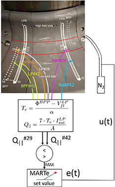
Figure 1. Top: schema of the combination of the BPP and Langmuir probes in the COMPASS divertor (adapted from [15]) and the approximate location of the injection valve. Bottom: schema of how the raw probe signals are connected to the MARTe acquisition system.
Download figure:
Standard image High-resolution imageThe third array of LP probes was biased to −270 V to measure the ion saturation current  . Combining together these three measurements allows to calculate the parallel heat flux
  that is deposited on the divertor tiles of COMPASS as:
where γ is the heat transmission coefficient and where  is the area of the LP probe equal to 2.8 mm2.
Independently, both targets of the divertor were observed by an infrared (IR) thermography system [16], which allows to measure the impacting heat fluxes at lower temporal (ΔtIR = 100 µs) but higher spatial (ΔRIR = 0.5 mm) resolution. A systematic comparison of IR and probe measurements allowed to determine the value of γ to be around 11 in the present plasma conditions [17].
Furthermore, the plasma radiation was monitored by arrays of absolute extended ultraviolet (AXUV) photodiodes [18], which can produce time evolving poloidal map of plasma emission by employing tomographic inversions. Last, a fast (8000 fps) visible camera was observing the divertor region near the different injection points. This diagnostic served as a proxy to estimate the time delay between the opening of the seeding valve and the neutral gas interaction with the plasma (increase of visible light emission).
The impurity seeding was executed via a port located in the divertor region, which was connected to a piezo valve capable of receiving real-time signals to control its state. The valve was connected to a gas reservoir filled with selected impurity species. The pressure in the reservoir was 2.1 or 1.5 bar for the experiments with high-field side (HFS) and low-field side (LFS) seeding, respectively. A pre-puff of 5 ms at 100% opening of the valve was always carried out to ensure correct opening of the piezo system.
Note that the divertor probes, AXUV photodiodes, IR camera and seeding port were located at different toroidal locations in the vessel. However, observations made by visible rapid imaging system (RIS) cameras [19] suggest that except for the very initial phase of the seeding, the impurity emission was toroidally symmetric (see figures 3 and 4 in [20]).
3. Real-time feedback system design
3.1. RTFS sensor selection
A key element of a well-designed RTFS is a diagnostic capable of delivering real-time measurements of heat flux at the divertor. In the past years, numerous such diagnostics were developed on different machines, for instance JT-60 [4], Alcator C-mod [6, 10], Asdex-U [21], JET [2], JET-ILW [22], TCV [23] and EAST [24], which vary in their principle of operation and also in complexity of related real-time calculations. In principle all these real-time systems can be divided into two categories: (1) the spectroscopic systems measuring the plasma emission (and resolving the so-called detachment front) and (2) the target systems, which measure some proxy of the impacting heat flux at the divertor tiles.
Spectroscopy systems have the advantage of being non-perturbative, however they are rather complex and require considerable computational power in order to function as real-time diagnostics. Another disadvantage is that they do not measure directly the parameter of interest—the target heat flux. The most advanced example of such system is MANTIS [23], which has been successfully employed at TCV tokamak.
The target systems are usually simple in their design, however the installation of a sensor, which is in contact with the impacting plasma and which has to withstand the related particle and heat fluxes, is required. Such sensor can be a divertor tile measuring the shunt currents [21], the embedded LP probe [22], or a surface thermocouple [6]. The last example represents a particularly sophisticated approach (including the real-time conversion of measured temperature to heat flux using an analog RC network), whose only minor weakness is its time resolution.
Given the unique diagnostic capabilities of the COMPASS tokamak, it was decided to employ the combined divertor probe array (described above) as the RTFS sensor (therefore falling into the category of the target systems). Its main advantage is the simple setup of operation—the heat flux is calculated only by subtracting and multiplying raw probe signals (see bottom of figure 1) and as such does not require complex post-processing, such as fitting of the I–V characteristics (as in case of the swept LP probes). Also, the divertor probes determine directly the impacting heat flux at the outer target, which is the quantity of interest. One specific advantage of this sensor is also the superior temporal resolution, which is significantly better than in case of spectroscopy, swept probes or surface thermocouples.
For technical reasons, the RTFS can only operate with a limited number of sensors—only 4 input channels in multi-threaded real-time executor [25] (MARTe—see section 3.3 for details) were available, meaning that probe sets from at most two radial locations could be used, and the subtraction of the floating potentials is done in dedicated electronics coupled to the MARTe input. In order to ensure robust RTFS performance, these two radial locations are needed to be carefully selected to be compatible with the most plasma scenarios.
Measurements from the divertor probes over 500 low confinement mode discharges were analysed (see figure 2) in order to determine the heat flux profile distribution over the outer target. At the time of analysis, these represented all low confinement discharges with available data from the divertor probe array. In order to account for different magnitudes of the parallel heat flux, in each discharge and for each probe,  was averaged over the whole flat-top duration and normalised by the integral heat flux (integrated along the R coordinate over the LFS divertor target), which corresponded to 100%. Then, the radial profiles of normalised
  were averaged over the set of selected discharges, resulting in the heat flux distribution presented in figure 2. This analysis yielded optimal probe sets #33 (R = 494.5 mm) and #42 (R = 528.6 mm) for the experiments.
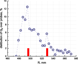
Figure 2. Heat flux distribution measured by divertor probes and calculated over a selection of around 500 L-mode discharges in the COMPASS database. Locations of selected probes are marked by red rectangles.
Download figure:
Standard image High-resolution image3.2. RTFS actuator
3.2.1. Valve location selection.
Previous experiments performed in the COMPASS tokamak have demonstrated that impurity seeding is an efficient way of reducing the target heat fluxes [20] and as such represents an effective actuator for the RTFS. However, a dedicated effort was required to optimise the way seeded impurities act onto the plasma for the purpose of real-time control (for instance, to avoid disruption).
Two locations of the seeding in the divertor were attempted. At first, a so-called HFS (R = 469 mm) [20] seeding injection point was investigated. In fact, in the particular plasma geometry used in this study, this location occurs to be in the private flux region according to the magnetic topology calculated by the EFIT reconstruction software. Later-on, the impurity seeding in LFS was investigated, by positioning the injection point just outside the outer strike point location, at R = 500 mm. Both injection point positions can be seen in figure 3.
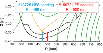
Figure 3. LFS seeding (red) and HFS seeding (blue) with respect to strike point location according to the EFIT reconstruction. The yellow line shows the separatrix, the black line, the machine wall and limiters.
Download figure:
Standard image High-resolution imageIn order to assess the influence of seeding location on nitrogen emission distribution, poloidal cross-sections of emission measured by AXUV photodiodes in two discharges with identical seeding rate of 2.0 × 10²⁰ s−1 but varied seeding location were compared. Figures 4(a)–(d) show radiation distribution during the LFS seeding, while figures 4(e)–(h) present results for the HFS seeding. It can be seen that in case of the LFS seeding the radiation is located in the vicinity of the x-point and possibly in the scrape-off layer (SOL) (the spatial coverage of the divertor region by the AXUV photodiodes was unfortunately not sufficient to resolve this area in greater detail), while the HFS seeding leads to radiation in the confined region above the x-point, which is an undesired effect with respect to plasma performance.
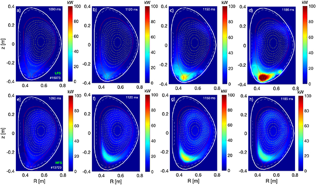
Figure 4. Plasma radiation as measured by AXUV photodiodes for LFS seeding (a)–(d) and HFS seeding (e)–(h) with identical nitrogen seeding rate of 2.0 × 10²⁰ s−1 (valve opens at 1100 ms).
Download figure:
Standard image High-resolution imageThe next step was to check plasma sustainability with respect to the amount of nitrogen inside the vessel. Discharges with different seeding rates were performed at the HFS and LFS locations. It was observed that HFS-seeded discharges result in disruption at lower seeding rates than LFS-seeded ones:  s−1 versus
  s−1, respectively [20].
In addition, it was observed that for both seeding locations, the maximum measured heat flux at the outer target undergoes a sharp decrease, which resembles to the so-called detachment cliff [26]. As shown in figure 5 for the LFS seeding, this feature is present also in discharges with higher seeding rates, although it occurs at earlier times (black curve at t ∼ 1225 ms vs other curves). The transition can also be sensed by comparing figures 4(c) and (d), where the x-point radiation intensifies after the transition. A similar feature is present also for the HFS seeding (see figure 11 in [20]), occurring for all seeding rates soon after the beginning of the seeding and with higher magnitude of the heat flux decrease than in the case of the LFS seeding. This type of behaviour is considered as a complication for control systems, because a sharp variation of the actuator does not lead to a smooth response on the target parameter, and is considered to be a more deleterious effect when seeding in the HFS region.
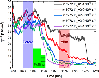
Figure 5. Evolution of the LFS peak heat flux  for different nitrogen seeding rates
  . The seeding waveform is indicated by the green area in the figure. In #15 977, the discharge ended in a disruption probably due to a too strong seeding.
Download figure:
Standard image High-resolution imageThe conclusion of all these observations was that LFS seeding is more suitable as an actuator for the RTFS than the HFS one.
3.2.2. Seeding gas selection.
Another essential task was to select the gas species to seed into the plasma. The most common gases used for impurity seeding in the divertor are nitrogen, neon and argon [27, 28]. Heavier gases are rarely employed to achieve detachment as they tend to radiate mostly in the confined plasma at higher temperatures. In contrast, lighter gases make seeding inefficient due to low levels of radiation cooling.
Experiments with variable seeding rate of neon were performed to complement the previously presented studies with nitrogen [20]. In these experiments, neon seeding always resulted in a disruption occurring ∼50 ms after the beginning of seeding, while nitrogen seeding allowed to demonstrate divertor plasma cooling without destabilising the discharge. In a later study [29], this problem was circumvented by a reduction of the pressure in the gas reservoir from 1.5 to 0.5 bar, which resulted in a smaller amount of injected neon during the pre-puff. However, probably due to the absence of chemical interactions with the PFCs (which can allow the impurity to stick to the wall), the characteristic time of removal of neon from the vessel was too long for practical use in RTFS because gas removal in COMPASS by pumping is generally very slow with respect to the duration of the discharges. A similar behaviour was also reported at Alcator C-mod [30]. On the basis of these experimental results nitrogen was selected for impurity seeding in the COMPASS tokamak.
3.2.3. Actuator magnitude.
Finally, an important feature of the RTFS actuator is its dynamic range, meaning how strongly it allows to regulate the divertor heat fluxes. Using measurements from the nitrogen seeding rate scan, it is possible to evaluate how effective the nitrogen seeding can be in power dissipation. This is illustrated in figure 5, where the figure of merit  (LFS peak heat flux) is depicted. Efficiency of the cooling can be estimated comparing the reference heat fluxes measured before seeding (indicated by the blue region) with heat fluxes measured after the course of seeding (red region). A reduction of
  by a factor of up to 11 (from 30 down to 2.7 MW m−2) was observed, which is comparable to results reported on other machines [30]. Note that such reduction is believed to be sufficient for the purpose of the COMPASS-U tokamak.
3.3. The RTFS reaction time
An initial estimation of the delay between the opening of the seeding valve and the beginning of radiation in the plasma was obtained in [20]  = 14 ms. However, this initial delay was not representative of the time constant of the continuously operating RTFS. Due to its construction, the seeding piezo valve usually does not open immediately on the first request (it sticks to the surface, probably due to friction) and, consequently, the first reaction time is substantially longer than the following ones. Furthermore, the presence of gas in the injection pipe itself contributes to a quicker delivery of the gas into the vessel. It was expected that once proper operation of the valve is ensured by a pre-programmed pre-puff, the subsequent changes of the valve state may result in more prompt reactions in the divertor region. To illustrate this point, in discharge #13 700 the pre-programmed seeding waveform was modified to form three discrete puffs with a duration of 10 ms each and 100% opening of the valve (see figure 6).

Figure 6. Pixel intensity recorded by a visible camera observing above the injection point in the divertor region, showing the nitrogen seeding time lag in discharge #13 700. The green rectangles indicate the three 10 ms nitrogen seeding puffs.
Download figure:
Standard image High-resolution imageThis figure shows the intensity evolution of a pixel recorded by the visible spectrum RIS camera [19] observing a location above the injection point in the divertor. The time lag between the initial opening of the valve and the plasma reaction (i.e. sharp increase in the pixel intensity) was estimated to be 15, 7 and 5 ms for the first, second and third puffs, respectively. It is therefore clear that after the first pre-puff, the time reaction between the valve opening and the gas interaction with the plasma falls below 10 ms. Such a time delay ( 10 ms) is reasonably short with respect to the duration of discharge flat-top (∼150 ms) and as such it allowed to employ the RTFS, providing that a pre-puff of 100% opening of the piezo-valve is always realized prior actual heat flux controlled seeding.
Note that the delay caused by the impurity action was significantly longer than the duty cycle of the real-time controller, which was 0.5 ms.
3.4. Constants for MARTe system
The MARTe system, adopted for real-time solution in the COMPASS tokamak, consists of blocks of code, generic application modules (GAMs). Every GAM is characterized by an input signal, an output signal and a configuration file. In GAM, the input signal is processed to produce a certain output signal, which can function as input in the next GAM. The real-time thread tracks the execution time. MARTe can handle a set of real-time threads running on the same CPU or in parallel. The feedback control system is a system where the controlled signal is compared to a desired reference signal and the discrepancy is used to compute corrective control action.
At COMPASS, a proportional integral (PI) controller was used as a feedback control system [31] to control the opening of the seeding valve. The PI controller calculates an error e(t) between the requested value (set-point—r(t)) and the actual value (processed variable—y(t)). The controller attempts to minimize the error of the control variable—heat flux in our case—by adjusting extra puffing to a new value u(t) determined by a weighted sum:
where Kp
is the proportional constant and Ki
is the integral constant. Kp
is responsible for changing the amount of gas based on the momentary difference in measured and desired heat flux. Ki
helps to avoid dramatic changes and consequently dump possible oscillations. These constants are predefined in the system and found experimentally. In our case, a series of discharges was performed to optimize the value of the two constants, the values  and
and  proved to provide the best results with such controller.
The data in MARTe are first sampled at frequency of 20 kHz and then decimated to 2 kHz. No smoothing was applied to the input signals.
4. Heat flux control demonstration
The RTFS was tested by setting the desired constant target heat flux and allowing the system to converge during the course of the discharge flat-top. Heat flux measurements originating from selected probes as calculated by the RTFS (red line) shown in figure 7 demonstrates the performance of the system with the selected target values set as 6 and 3 MW m−2, respectively. To further illustrate the decrease in heat flux reaching the target, these measurements are also compared with the peak heat flux measured by an IR camera [16] (green line) and by all probes at the outer target (yellow line). For the IR measurements the background signal (measured in the private flux region) was subtracted. Note that the RTFS signal exhibits fluctuations, which most probably originate from electromagnetic interference with other tokamak systems during signal transmission into the RTFS.

Figure 7. Two sample discharges with RTFS. The red curve shows the peak heat flux between the two probes as calculated by the RTFS (probes #33 and #42), the yellow line shows the peak heat flux on the whole LFS target, the green line shows the LFS peak heat flux measured by IR thermography and the blue line shows the real-time particle seeding rate. Left: requested value was set to 6 MW m−2, obtained mean value was 6.7 MW m−2. Right: requested value was set to 3 MW m−2, obtained mean value was 5.3 MW m−2 in the RTFS working time interval. In the time interval from 1120 ms to 1200 (without the last peak at 1210 ms) the mean value is 3.2 MW m−2.
Download figure:
Standard image High-resolution image
One can notice the good agreement between the LFS peak heat flux measured by IR and all probes, showing the relevance of using the BPP/LP probe combination for heat flux control. Once the RTFS is activated, the peak heat flux reaches values close to the preset ones. This is a considerably smaller value than the maximum peak heat flux during the unseeded phase (20 MW m−2), meaning a reduction in the heat flux by approximately factors of 3 and 7, respectively. This demonstrated that impurity seeding in the COMPASS tokamak can be effectively used to control the heat fluxes. It is important to mention that the later discharge (figure 7(b)) represents the lower limit of applicability of our RTFS. Further reduction of heat fluxes became problematic, due to very weak voltages of the signals connected to MARTe (≈0.2 V), which were comparable to the noise level.
Note that nitrogen seeded discharges in COMPASS can exhibit the so-called detachment cliff [26], as already mentioned earlier, which is characterised by a sudden drop of temperature, resulting in a transition to partial detachment and strong reduction of the target heat flux. Such feature is in general detrimental for real-time heat flux control since it does not allow for smooth control of the desired parameter. Detailed measurements of the heat flux footprint have revealed that the detachment cliff influences mostly the heat flux close to the strike point (see figure 16 in [20]), while the heat flux profile further away is not affected so strongly. Since the aim is to control the peak heat flux, our real-time system remains reliable even when the cliff occurs (which is the case in both discharges presented in figure 7)—during the transition the peak heat flux in such case is relocated into the far SOL region, where it is measured by probe set #42. Adding more probes to the RTFS (especially in the far SOL) would help to further improve the reliability of the RTFS.
In both cases the system exhibited a systematic overshoot during the first 50 ms of seeding, which was caused by slow removal of the nitrogen from the vessel (following the initial strong pre-puff). Apparently, the characteristic time constant of this process is significantly longer than that of nitrogen injection. While this is not an issue from the point of view of divertor protection, it enhances the risk of MARFE formation (and subsequent disruption) or excessive cooling of the core plasma.
It can be seen that for  1120 ms the real-time measurements with the use of the selected set of probes are equal to the reference measurements by IR and the entire probe array (red curve vs green and yellow ones). However, at the beginning of the discharge (1050–1080 ms) when the outer strike point was not yet at its desired location, there is a noticeable difference between them. In such conditions, the real-time probes at the two selected locations are not capable of capturing the true maximum of the heat flux. It shows the importance of careful probe location selection.
5. Conclusions
This paper presents a novel real-time feedback control concept in order to optimize the reduction of the heat flux that falls onto the divertor of the COMPASS tokamak and its possible use for other machines. The main innovative idea of the presented system was the use of combined LP and BPP measurements. The simplicity of such measurements (direct measurements of floating potentials and saturation currents) has shown to have the following advantages: an easy implementation, a high temporal resolution and direct measurements of the heat flux reaching the divertor tiles. However, for such a system a proper design is required, as one has to avoid shadowing between the LP probes or to properly measure the saturation current with a sufficiently negative bias voltage.
A number of experimental studies were performed in order to characterise and optimise the effect of impurity seeding on the divertor heat flux. It was found that in our experiments nitrogen injection performed better than neon injection and that the seeding location should be in the LFS of the divertor. Then, the RTFS was successfully tested in low confinement ohmic discharges, where it allowed to reduce the impacting heat flux by a factor of 7, reaching a stable peak parallel heat flux of about 3 MW m−2. The use of the feedback system in ELMy H-mode was also planned but, so far, any attempt to inject impurities in such a scenario resulted in the loss of edge localised mode (ELM) and the transition to unstable ELM-free regime. Nevertheless, the planned installation of a 1 MW NBI system at COMPASS should allow to resolve this issue and further research and development is foreseen.
First attempts to employ the RTFS have revealed very different time scales related to nitrogen injection (5 ms) and removal (50 ms). This is a challenging condition for the integral part of the real-time PI controller. In future, more complicated controller scheme can be developed to account for this effect.
The principal objective of this work was to develop a system which could be implemented at the COMPASS-U tokamak (currently in its design phase) [11] because the heat fluxes are expected to be so high that the divertor PFCs would be damaged if no heat flux mitigation would be applied. While the characterisation of the impurity injection (which gas, which location...) is probably rather machine-specific, the use of the combined probe array as a real-time feedback sensor can be easily adapted for to other machines. The experiments presented in this work confirm that such a system could be an effective means of protecting the divertors in next step devices.
Acknowledgments
Part of this work has been carried out within the framework of MEYS projects COMPASS RI (No. CZ.02.1. 01/0.0/0.0/16_013/0001551) and LM2018117 and co-funded from European structural and investment funds. This work has been carried out within the framework of the EUROFusion Consortium and has received funding from the Euroatom research and training programme 2014–2018 and 2019–2020 under Grant Agreement No. 633053. The views and opinions expressed herein do not necessarily reflect those of the European Commission.