
Permeable Membranes PUR/TETA and PUR/TEPA for CO2 Capture Prepared with One-Step Electrospinning Technology

 , , , , and
Abstract
: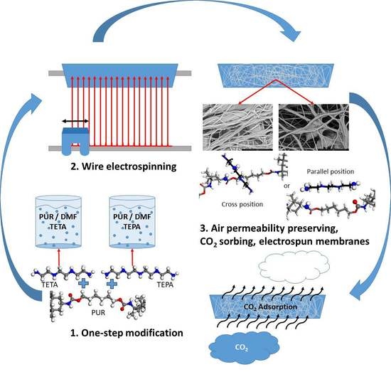
1. Introduction
- -
- The modifying agent is dissolved in a spinning solution, and no subsequent treatment is necessary;
- -
- This technology does not destroy the porosity and air permeability of the membrane as in the case of various after-treatment procedures;
- -
- Our air membrane is easy to design as a cascade sorption unit working in the stream of gas.
2. Materials and Methods
2.1. Materials and Spinning Solution
2.2. Spinning Conditions
2.3. Membrane Characterization Methods
3. Results and Discussion
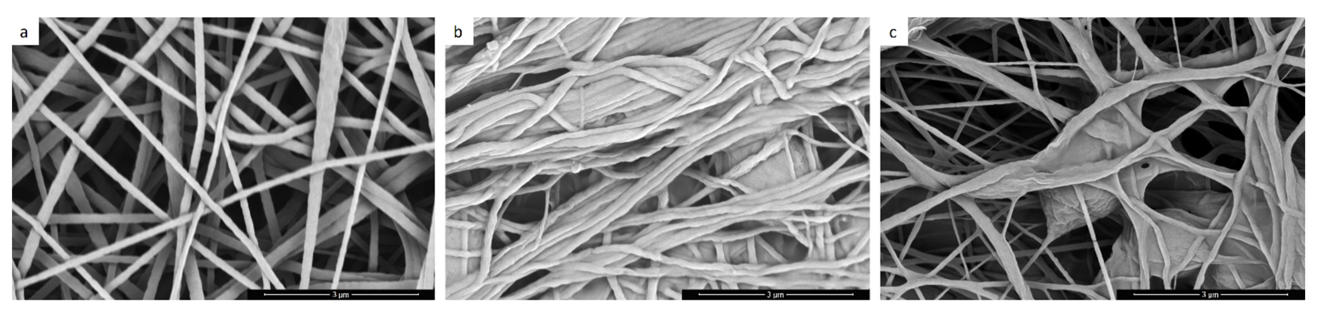
3.1. Fiber Morphology, Air Permeability, and CO2 Sorption Capacity
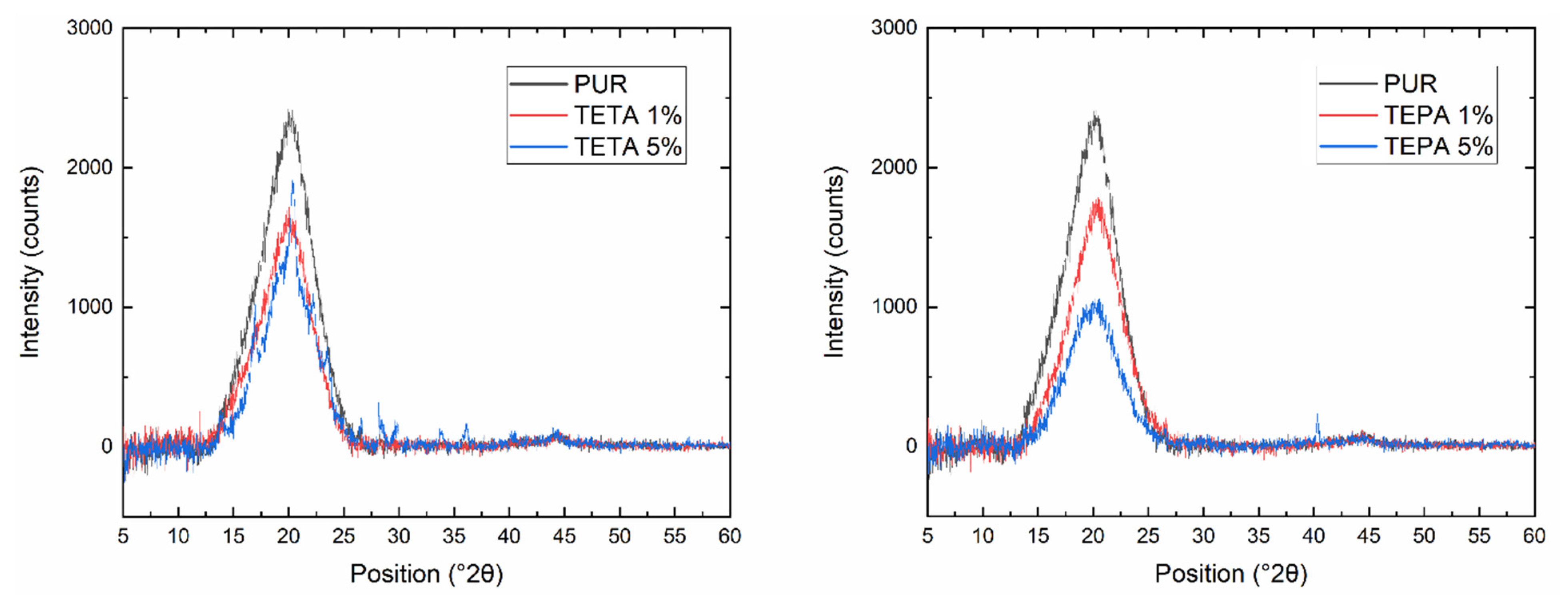
3.2. XRD Analysis
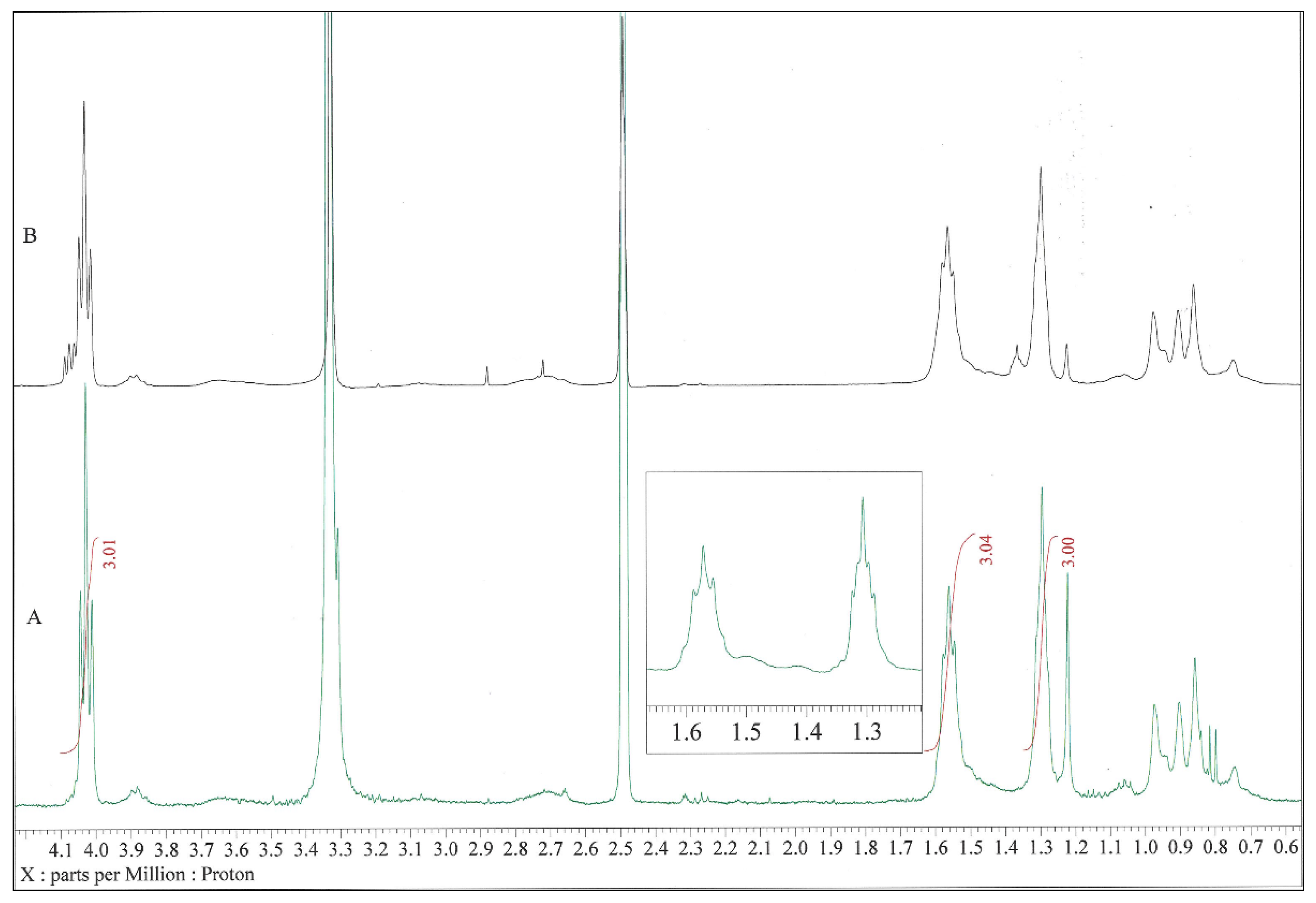
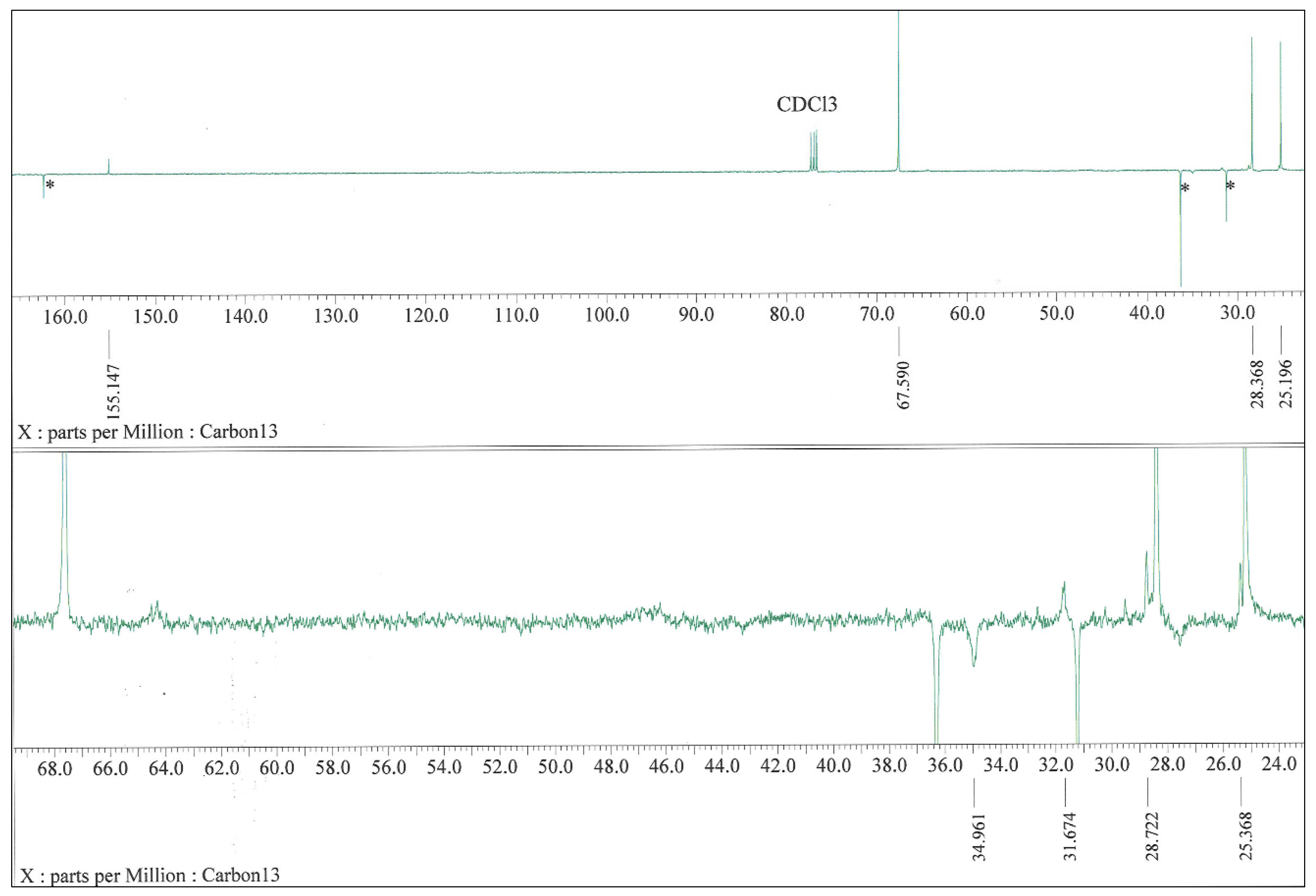
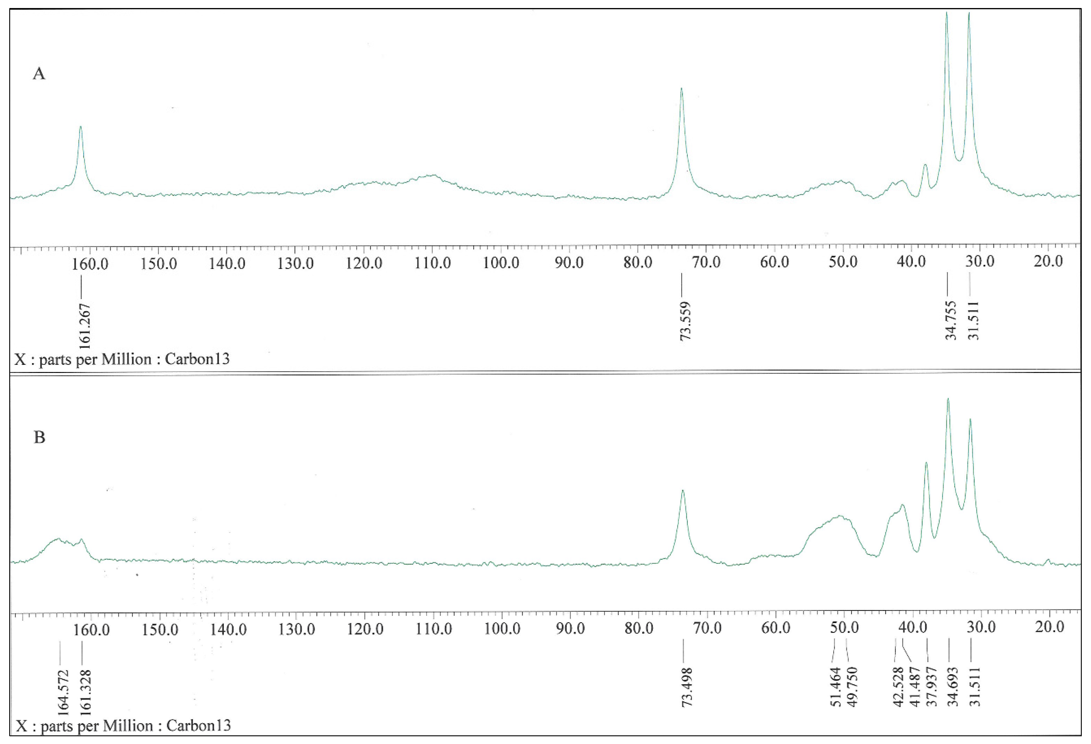
3.3. Surface Chemistry of the PUR/TETA(TEPA) Membranes
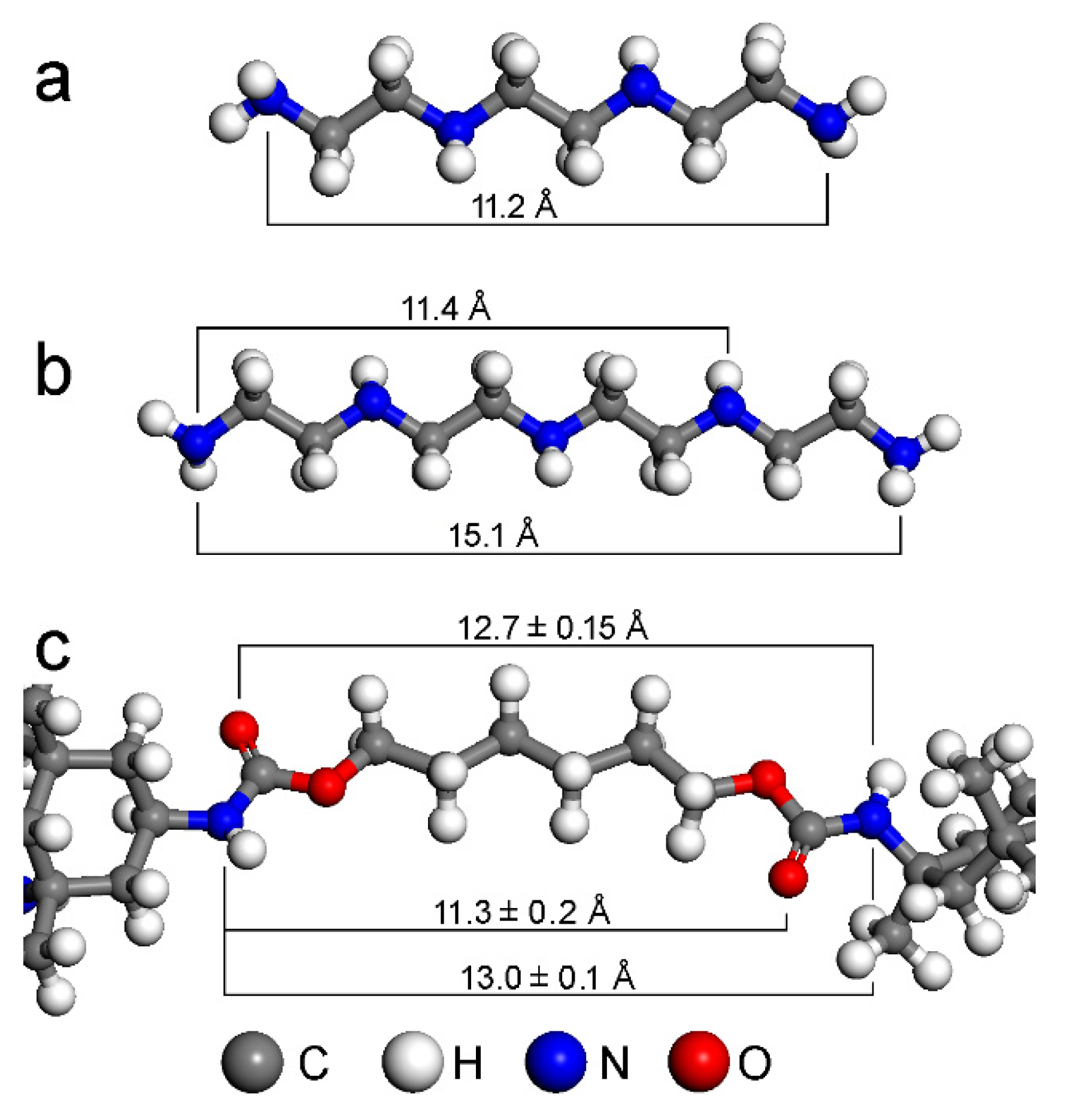
3.4. PUR-TETA(TEPA) Interactions and Effect on the Membrane Structure and Properties
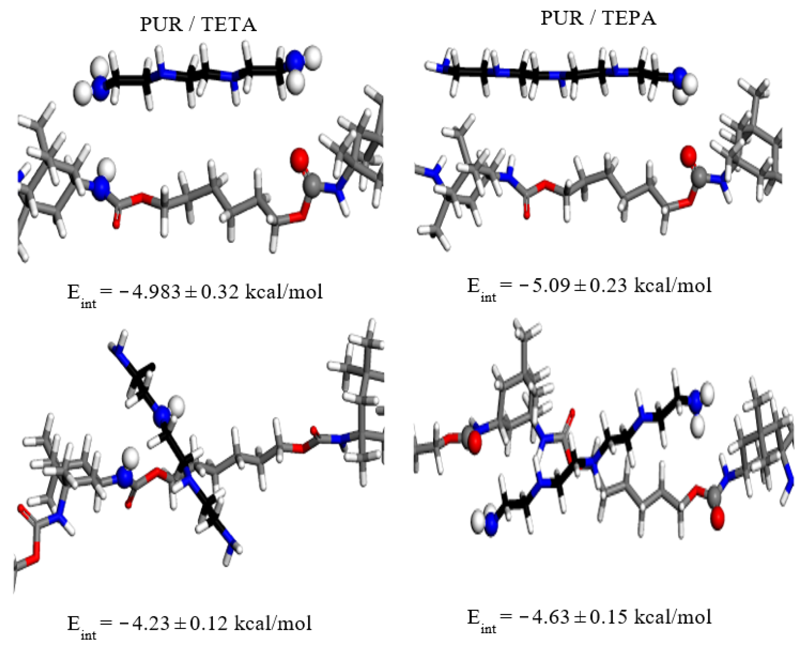
3.5. Molecular Modeling of the PUR-Amine Interactions
4. Conclusions
Author Contributions
Funding
Data Availability Statement
Acknowledgments
Conflicts of Interest
References
- Mills, B.J.; Krause, A.J.; Scotese, C.R.; Hill, D.J.; Shields, G.A.; Lenton, T.M. Modelling the long-term carbon cycle, atmospheric CO2, and Earth surface temperature from late Neoproterozoic to present day. Gondwana Res. 2018, 67, 172–186. [Google Scholar] [CrossRef]
- Kweku, D.W.; Bismark, O.; Maxwell, A.; Desmond, K.A.; Danso, K.B.; Oti-Mensah, E.A.; Quachie, A.T.; Adormaa, B.B. Greenhouse Effect: Greenhouse Gases and Their Impact on Global Warming. J. Sci. Res. Rep. 2018, 17, 1–9. [Google Scholar] [CrossRef]
- Tan, X.; Liu, Y.; Dong, H.; Xiao, Y.; Zhao, Z. The health consequences of greenhouse gas emissions: A potential pathway. Environ. Geochem. Health 2022, 44, 2955–2974. [Google Scholar] [CrossRef] [PubMed]
- Song, C.; Liu, Q.; Ji, N.; Deng, S.; Zhao, J.; Li, Y.; Song, Y.; Li, H. Alternative pathways for efficient CO2 capture by hybrid processes—A review. Renew. Sustain. Energy Rev. 2017, 82, 215–231. [Google Scholar] [CrossRef]
- Sanni, E.S.; Sadiku, E.R.; Okoro, E.E. Novel Systems and Membrane Technologies for Carbon Capture. Int. J. Chem. Eng. 2021, 2021, 6642906. [Google Scholar] [CrossRef]
- Al-Mamoori, A.; Rownaghi, A.A.; Rezaei, F. Carbon Capture and Utilization Update. Energy Technol. 2017, 5, 834–849. [Google Scholar] [CrossRef] [Green Version]
- Drioli, E.; Barbieri, G.; Brunetti, A. Membrane Engineering for the Treatment of Gases: Volume 1: Gas-separation Problems with Membranes. In Recent High Performance Polymer Membranes for CO2 Separation; The Royal Society of Chemistry: London, UK, 2011; Volume 1, pp. 84–124. [Google Scholar]
- Vopička, O.; de Angelis, M.G.; Sarti, G.C. Mixed gas sorption in glassy polymeric membranes: I. CO2/CH4 and n-C4/CH4 mixtures sorption in poly(1-trimethylsilyl-1-propyne) (PTMSP). J. Membr. Sci. 2014, 449, 97–108. [Google Scholar] [CrossRef]
- Kim, H.; Lee, K.S. Energy analysis of an absorption-based CO2 capture process. Int. J. Greenh. Gas Control 2017, 56, 250–260. [Google Scholar] [CrossRef]
- Rochelle, G.T. Amine Scrubbing for CO2 Capture. Science 2009, 325, 1652–1654. [Google Scholar] [CrossRef]
- Ho, M.T.; Allinson, G.W.; Wiley, D.E. Reducing the Cost of CO2 Capture from Flue Gases Using Membrane Technology. Ind. Eng. Chem. Res. 2008, 47, 1562–1568. [Google Scholar] [CrossRef]
- Zainab, G.; Babar, A.A.; Iqbal, N.; Wang, X.; Yu, J.; Ding, B. Amine-impregnated porous nanofiber membranes for CO2 capture. Compos. Commun. 2018, 10, 45–51. [Google Scholar] [CrossRef]
- Abbasi, A.; Nasef, M.M.; Kheawhom, S.; Faridi-Majidi, R.; Takeshi, M.; Abouzari-Lotf, E.; Choong, T. Amine functionalized radiation induced grafted polyolefin nanofibers for CO2 adsorption. Radiat. Phys. Chem. 2018, 156, 58–66. [Google Scholar] [CrossRef]
- Nasef, M.M.; Ting, T.; Abbasi, A.; Layeghi-Moghaddam, A.; Alinezhad, S.S.; Hashim, K. Radiation grafted adsorbents for newly emerging environmental applications. Radiat. Phys. Chem. 2016, 118, 55–60. [Google Scholar] [CrossRef]
- Zainab, G.; Iqbal, N.; Babar, A.A.; Huang, C.; Wang, X.; Yu, J.; Ding, B. Free-standing, spider-web-like polyamide/carbon nanotube composite nanofibrous membrane impregnated with polyethyleneimine for CO2 capture. Compos. Commun. 2017, 6, 41–47. [Google Scholar] [CrossRef]
- Wang, J.; Adelodun, A.A.; Oh, J.M.; Jo, Y.M. TEPA impregnation of electrospun carbon nanofibers for enhanced low-level CO2 adsorption. Nano Converg. 2020, 7, 7. [Google Scholar] [CrossRef]
- Wang, X.; Li, B. Electrospun Nanofibrous Sorbents and Membranes for Carbon Dioxide Capture. In Electrospun Nanofibers for Energy and Environmental Applications; Ding, B., Yu, J., Eds.; Springer: Berlin/Heidelberg, Germany, 2014; pp. 249–263. [Google Scholar]
- Choi, C.; Kadam, R.L.; Gaikwad, S.; Hwang, K.-S.; Han, S. Metal organic frameworks immobilized polyacrylonitrile fiber mats with polyethyleneimine impregnation for CO2 capture. Microporous Mesoporous Mater. 2020, 296, 110006. [Google Scholar] [CrossRef]
- Othman, F.E.C.; Yusof, N.; Petrů, M.; Nordin, N.A.H.M.; Hamid, M.F.; Ismail, A.F.; Rushdan, A.I.; Abu Hassan, S. Polyethyleneimine-impregnated activated carbon nanofiber composited graphene-derived rice husk char for efficient post-combustion CO2 capture. Nanotechnol. Rev. 2022, 11, 926–944. [Google Scholar] [CrossRef]
- Heo, Y.-J.; Zhang, Y.; Rhee, K.Y.; Park, S.-J. Synthesis of PAN/PVDF nanofiber composites-based carbon adsorbents for CO2 capture. Compos. Part B Eng. 2018, 156, 95–99. [Google Scholar] [CrossRef]
- Chiang, Y.-C.; Wu, C.-Y.; Chen, Y.-J. Effects of activation on the properties of electrospun carbon nanofibers and their adsorption performance for carbon dioxide. Sep. Purif. Technol. 2019, 233, 116040. [Google Scholar] [CrossRef]
- Iqbal, N.; Babar, A.A.; Zainab, G.; Ding, B.; Yu, J.; Wang, X. Chapter 20—Electrospun Nanofibers for Carbon Dioxide Capture. In Electrospinning: Nanofabrication and Applications; Ding, B., Wang, X., Yu, J., Eds.; William Andrew Publishing: Norwich, NY, USA, 2019; pp. 619–640. [Google Scholar]
- Jung, H.; Jo, D.H.; Lee, C.H.; Chung, W.; Shin, D.; Kim, S.H. Carbon Dioxide Capture Using Poly(ethylenimine)-Impregnated Poly(methyl methacrylate)-Supported Sorbents. Energy Fuels 2014, 28, 3994–4001. [Google Scholar] [CrossRef]
- Jung, H.; Lee, C.H.; Jeon, S.; Jo, D.H.; Huh, J.; Kim, S.H. Effect of amine double-functionalization on CO2 adsorption behaviors of silica gel-supported adsorbents. Adsorption 2016, 22, 1137–1146. [Google Scholar] [CrossRef]
- Kludský, M.; Vopička, O.; Matějka, P.; Hovorka, Š.; Friess, K. Nafion® modified with primary amines: Chemical structure, sorption properties and pervaporative separation of methanol-dimethyl carbonate mixtures. Eur. Polym. J. 2018, 99, 268–276. [Google Scholar] [CrossRef]
- Kuang, Y.; He, H.; Chen, S.; Wu, J.; Liu, F. Adsorption behavior of CO2 on amine-functionalized polyacrylonitrile fiber. Adsorption 2019, 25, 693–701. [Google Scholar] [CrossRef]
- Lin, Z.F.; Wei, J.W. CO2 Adsorption on Activated Carbon/SBA-15 with TETA/TEPA Modification. Key Eng. Mater. 2017, 735, 164–167. [Google Scholar] [CrossRef]
- Ma, L.; Bai, R.; Hu, G.; Chen, R.; Hu, X.; Dai, W.; Dacosta, H.F.M.; Fan, M. Capturing CO2 with Amine-Impregnated Titanium Oxides. Energy Fuels 2013, 27, 5433–5439. [Google Scholar] [CrossRef]
- Qing, Y.; Yu, Z.; Ming, L.; Yao, S. Adsorption of Low Concentration CO2 by Modified Carbon Nanotubes under Ambient Temperature. Acta Phys.-Chim. Sin. 2012, 28, 1223–1229. [Google Scholar] [CrossRef]
- Wei, J.; Lin, Z.; He, Z.; Geng, L.; Liao, L. Bagasse Activated Carbon with TETA/TEPA Modification and Adsorption Properties of CO2. Water Air Soil Pollut. 2017, 228, 128. [Google Scholar] [CrossRef]
- Zhang, J.; Zhao, Q.; Wang, S.; Tan, X. Direct capture of low concentration CO2 using tetraethylenepentamine-grafted polyacrylonitrile hollow fibers. Sep. Purif. Technol. 2022, 287, 120562. [Google Scholar] [CrossRef]
- Jiao, J.; Cao, J.; Xia, Y.; Zhao, L. Improvement of adsorbent materials for CO2 capture by amine functionalized mesoporous silica with worm-hole framework structure. Chem. Eng. J. 2016, 306, 9–16. [Google Scholar] [CrossRef]
- Kim, T.-J.; Li, B.; Hägg, M.-B. Novel fixed-site-carrier polyvinylamine membrane for carbon dioxide capture. J. Polym. Sci. Part B Polym. Phys. 2004, 42, 4326–4336. [Google Scholar] [CrossRef]
- Kim, S.; Lee, Y.M. High performance polymer membranes for CO2 separation. Curr. Opin. Chem. Eng. 2013, 2, 238–244. [Google Scholar] [CrossRef]
- Zhao, L.; Weber, M.; Stolten, D. Comparative Investigation of Polymer Membranes for Post-combustion Capture. Energy Procedia 2013, 37, 1125–1134. [Google Scholar] [CrossRef] [Green Version]
- Tong, Z.; Ho, W.W. New sterically hindered polyvinylamine membranes for CO2 separation and capture. J. Membr. Sci. 2017, 543, 202–211. [Google Scholar] [CrossRef]
- Bai, F.; Liu, X.; Sani, S.; Liu, Y.; Guo, W.; Sun, C. Amine functionalized mesocellular silica foam as highly efficient sorbents for CO2 capture. Sep. Purif. Technol. 2022, 299, 121539. [Google Scholar] [CrossRef]
- Anyanwu, J.-T.; Wang, Y.; Yang, R.T. Tunable amine loading of amine grafted mesoporous silica grafted at room temperature: Applications for CO2 capture. Chem. Eng. Sci. 2022, 254, 117626. [Google Scholar] [CrossRef]
- Sharmin, E.; Zafar, F. Polyurethane: An Introduction. In Polyurethane, 1st ed.; Zafar, F., Sharmin, E., Eds.; InTech: Rijeka, Croatia, 2012; pp. 3–6. [Google Scholar]
- Das, A.; Mahanwar, P. A brief discussion on advances in polyurethane applications. Adv. Ind. Eng. Polym. Res. 2020, 3, 93–101. [Google Scholar] [CrossRef]
- Jirsak, O.; Sanetrnik, F.; Lukas, D.; Kotek, V.; Martinova, L.; Chaloupek, J. Method of Nanofibres Production from A Polymer Solution Using Electrostatic Spinning and A Device for Carrying out the Method. U.S. Patent 7585437B2, 8 September 2009. [Google Scholar]
- Ibrahim, H.M.; Klingner, A. A review on electrospun polymeric nanofibers: Production parameters and potential applications. Polym. Test. 2020, 90, 106647. [Google Scholar] [CrossRef]
- Schindelin, J.; Arganda-Carreras, I.; Frise, E.; Kaynig, V.; Longair, M.; Pietzsch, T.; Preibisch, S.; Rueden, C.; Saalfeld, S.; Schmid, B.; et al. Fiji: An open-source platform for biological-image analysis. Nat. Methods 2012, 9, 676–682. [Google Scholar] [CrossRef] [Green Version]
- Benkocká, M.; Kolářová, K.; Matoušek, J.; Semerádtová, A.; Šícha, V.; Kolská, Z. Nanocomposite of polystyrene foil grafted with metallaboranes for antimicrobial activity. Appl. Surf. Sci. 2018, 441, 120–129. [Google Scholar] [CrossRef]
- Benkocká, M.; Lupínková, S.; Matoušek, J.; Kolářová, K.; Kolská, Z. Antimicrobial and optical properties of PET chemically modified and grafted with borane compounds. RSC Adv. 2018, 8, 15001–15008. [Google Scholar] [CrossRef]
- Kolská, Z.; Kasálková, N.S.; Siegel, J.; Švorčík, V. Electrokinetic Potential for Characterization of Nanosctructured Solid Flat Surfaces. J. Nano Res. 2013, 25, 31–39. [Google Scholar] [CrossRef]
- Kolská, Z.; Řezníčková, A.; Svorcik, V. Surface characterization of polymer foils. e-Polymers 2012, 12, 960–972. [Google Scholar] [CrossRef]
- Sun, H. COMPASS: An ab Initio Force-Field Optimized for Condensed-Phase ApplicationsOverview with Details on Alkane and Benzene Compounds. J. Phys. Chem. B 1998, 102, 7338–7364. [Google Scholar] [CrossRef]
- Ryšánek, P.; Čapková, P.; Štojdl, J.; Trögl, J.; Benada, O.; Kormunda, M.; Kolská, Z.; Munzarová, M. Stability of antibacterial modification of nanofibrous PA6/DTAB membrane during air filtration. Mater. Sci. Eng. C 2018, 96, 807–813. [Google Scholar] [CrossRef] [PubMed]
- Čapková, P.; Kormunda, M.; Kolská, Z.; Trögl, J.; Munzarová, M.; Ryšánek, P. Electrospun Antimicrobial PVDF-DTAB Nanofibrous Membrane for Air Filtration: Effect of DTAB on Structure, Morphology, Adhesion, and Antibacterial Properties. Macromol. Mater. Eng. 2018, 303, 1700415. [Google Scholar] [CrossRef]
- Ryšánek, P.; Malý, M.; Čapková, P.; Kormunda, M.; Kolská, Z.; Gryndler, M.; Novák, O.; Hocelíková, L.; Bystrianský, L.; Munzarová, M. Antibacterial modification of nylon-6 nanofibers: Structure, properties and antibacterial activity. J. Polym. Res. 2017, 24, 208. [Google Scholar] [CrossRef]
- Marin, L.; Dragoi, B.; Olaru, N.; Perju, E.; Coroaba, A.; Doroftei, F.; Scavia, G.; Destri, S.; Zappia, S.; Porzio, W. Nanoporous furfuryl-imine-chitosan fibers as a new pathway towards eco-materials for CO2 adsorption. Eur. Polym. J. 2019, 120, 109214. [Google Scholar] [CrossRef]
- Imanian, Z.; Hormozi, F.; Torab-Mostaedi, M.; Asadollahzadeh, M. Highly selective adsorbent by gamma radiation-induced grafting of glycidyl methacrylate on polyacrylonitrile/polyurethane nanofiber: Evaluation of CO2 capture. Sep. Purif. Technol. 2022, 289, 120749. [Google Scholar] [CrossRef]
- Zheng, W.; Li, Z.; Sun, T.; Ruan, X.; Dai, Y.; Li, X.; Zhang, C.; He, G. PAN electrospun nanofiber skeleton induced MOFs continuous distribution in MMMs to boost CO2 capture. J. Membr. Sci. 2022, 650, 120330. [Google Scholar] [CrossRef]


| Sample | MMD Nanofiber Diameter (nm) | Air Permeability (m/s) | CO2 Adsorbed Volume (cm3/g) |
|---|---|---|---|
| PUR | 290 ± 37 | 0.002 ± 0.0002 | 2.7 ± 0.9 |
| PUR/TETA (1 wt.%) | 170 ± 24 | 0.05 ± 0.004 | 8.1 ± 1.9 |
| PUR/TETA (5 wt.%) | 164 ± 35 | 0.13 ± 0.02 | 8.09 ± 2.0 |
| PUR/TEPA (1 wt.%) | 174 ± 40 | 0.08 ± 0.01 | 6.8 ± 1.8 |
| PUR/TEPA (5 wt.%) | 166 ± 45 | 0.02 ± 0.003 | 13.9 ± 2.3 |
| Sample | Static Contact Angle (°) | Zeta Potential (mV) |
|---|---|---|
| PUR | 100 ± 7 | −35.28 ± 0.1 |
| PUR/TETA (1 wt.%) | 120 ± 3 | −6.72 ± 0.3 |
| PUR/TETA (5 wt.%) | 0 | 0.71 ± 0.4 |
| PUR/TEPA (1 wt.%) | 129 ± 10 | 30.34 ± 1.5 |
| PUR/TEPA (5 wt.%) | 0 | 0.39 ± 0.9 |
| Sample | Amine (wt.%) | Eint (kcal/mol) |
|---|---|---|
| 2PUR (78 seg) | 0.00 | −1959 ± 21 |
| 2PUR (78 seg) + 4TETA | 1.13 | −2152 ± 32 (−1977 ± 25) |
| 2PUR (78 seg) + 3TEPA | 1.10 | −2153 ± 30 (−1939 ± 20) |
| 2PUR (78 seg) + 18TETA | 4.91 | −3038 ± 47 (−1951 ± 22) |
| 2PUR (78 seg) + 14TEPA | 4.94 | −2982 ± 41 (−1971 ± 22) |
Publisher’s Note: MDPI stays neutral with regard to jurisdictional claims in published maps and institutional affiliations. |
© 2022 by the authors. Licensee MDPI, Basel, Switzerland. This article is an open access article distributed under the terms and conditions of the Creative Commons Attribution (CC BY) license (https://creativecommons.org/licenses/by/4.0/).
Share and Cite
Hoskovec, J.; Čapková, P.; Vostiňáková, M.; Ryšánek, P.; Kaule, P.; Tokarský, J.; Benada, O.; Blechta, V. Permeable Membranes PUR/TETA and PUR/TEPA for CO2 Capture Prepared with One-Step Electrospinning Technology. Fibers 2022, 10, 100. https://doi.org/10.3390/fib10110100
Hoskovec J, Čapková P, Vostiňáková M, Ryšánek P, Kaule P, Tokarský J, Benada O, Blechta V. Permeable Membranes PUR/TETA and PUR/TEPA for CO2 Capture Prepared with One-Step Electrospinning Technology. Fibers. 2022; 10(11):100. https://doi.org/10.3390/fib10110100
Chicago/Turabian StyleHoskovec, Jakub, Pavla Čapková, Monika Vostiňáková, Petr Ryšánek, Pavel Kaule, Jonáš Tokarský, Oldřich Benada, and Vratislav Blechta. 2022. "Permeable Membranes PUR/TETA and PUR/TEPA for CO2 Capture Prepared with One-Step Electrospinning Technology" Fibers 10, no. 11: 100. https://doi.org/10.3390/fib10110100