Article

Dynamic Impact Resistance and Scratch Adhesion of AlCrN Coatings Sputtered Using Cathodic Arc Glow Discharge

1
Institute of Scientific Instruments of the Czech Academy of Sciences, Královopolská 147, CZ-61264 Brno, Czech Republic
2
Platit AG, Eichholzstrasse 9, CH-2545 Selzach, Switzerland
3
Platit a.s., Průmyslová 3020/3, CZ-78701 Šumperk, Czech Republic
4
Department of Physical Electronics, Faculty of Science, Masaryk University, Kotlářská 2, CZ-61137 Brno, Czech Republic
*
Author to whom correspondence should be addressed.
Coatings 2023, 13(3), 515; https://doi.org/10.3390/coatings13030515
Submission received: 31 January 2023 / Revised: 21 February 2023 / Accepted: 22 February 2023 / Published: 25 February 2023
(This article belongs to the Special Issue Chemical/Physical Vapor Deposition Coatings on Metallic Substrates)

Abstract

:
AlCrN coatings, which are characterized by high hardness and good wear resistance, are often used for drilling, milling, and punching tools. Therefore, the study of the behaviour of these coatings under cyclic impact loading is essential for their optimization. Our previous work has focused on the study of the composition and microstructure of AlCrN coatings prepared using a cathodic arc deposition system with a SCIL® controller that controls the average ion energy per deposited atom (Ed). Two sets of coatings were prepared in two different modes, with a metal target and with a poisoned target. The chemical compositions of the coatings were very similar regardless of their deposition conditions, but the structure and mechanical properties of the coatings depended strongly on Ed. The present work focused on the scratch adhesion and impact wear of these two sets of AlCrN coatings. The lifetimes of both sets of samples under repeated dynamic impacts were tested using a dynamic impact tester with a WC-Co ball. It was shown that the impact behaviour of the coatings prepared in the metallic regime does not depend on the deposition conditions. However, the impact behaviour of the coatings deposited in poisoned mode was improved by increasing Ed.

1. Introduction

Metal nitride coatings deposited by physical vapor deposition (PVD) are often used in industry due to their improved mechanical and tribological properties, which lead to reduced wear and increased lifetimes of various industrial tools and components [1,2,3,4,5,6,7,8]. Some of these PVD-coated tools are subjected to cyclic dynamic or impact loading during industrial use [1,2]. The cyclic nature and dynamics of these stresses can significantly affect the lifetime of such tools [3,4]. Therefore, it is desirable to study the fatigue of PVD coatings under cyclic dynamic loading [9,10,11,12,13].
AlCrN protective coatings are widely used in manufacturing and machining operations with cyclic impacts or dynamic loads, namely drilling, milling, cutting, and punching [14,15,16,17]. Due to the wide range of applications, AlCrN coatings have been the subject of intense research in recent years. Their properties that are favourable for practical applications such as high hardness [18], high thermal stability and oxidation resistance [16], abrasion resistance [19], and low coefficient of friction [20] have been studied. These mechanical and tribological properties of the AlCrN system are strongly dependent on the chemical composition and microstructure [21,22], which are related to the sputtering conditions, such as a substrate bias [23], ion flux ratio during deposition [14,24], or the nitrogen content in the case of the reactive sputtering [25]. Currently, the improvement of AlCrN coatings is mainly focused on tuning the coating structure, such as through alloying [8,26,27], multilayer systems [8,20,28], and gradient coatings [29,30]. Other ways to improve the properties of AlCrN include modifying the substrate properties, such as by nitriding [31,32], or modifying and tuning the coating deposition process [8,33].
Improving the properties of the AlCrN coating using a novel approach to its deposition was the goal of our previous study [14]. Zemlicka et al. presented two series of AlCrN coatings sputtered using the SCIL® cathodic arc discharge technology introduced by PLATIT AG [14]. This technology enables control of plasma ionization during the deposition process and thus control of the coating’s microstructure and some mechanical properties. The coatings were sputtered in two modes, the metallic (M-coatings) and the poisoned (compound mode; C-coatings), and were described by the average ion energy per deposited atom Ed and the ion-deposition flux ratio (Ji/Jd). It was shown that different sputtered conditions in both regimes resulted in different microstructures; the C-coatings exhibited a cubic structure similar to NaCl, while the M-coatings exhibited a hexagonal structure or a mixture of hexagonal and cubic structures. However, the chemical composition of the M-coatings and C-coatings were almost the same: Al35Cr17N49 and Al33Cr16N51, respectively. The effective elastic modulus of all coatings depended strongly on the structure, but no dependence on Ed was observed. In contrast, the hardness of the coatings showed a strong dependence on Ed. Moreover, cutting tests showed that the tool life of AlCrN-coated end-milling tools under real working conditions increased with increasing Ed, i.e., with increasing degree of plasma ionization by SCIL® technology (PLATIT AG, Selzach, Switzerland). Further information and a detailed discussion can be found in [14].
Although AlCrN coating is commonly used as a protective coating for tools exposed to cyclic dynamic loading, there are only a few comprehensive studies addressing this type of loading [34]. Some studies only partially address impact loading, e.g., comparing cratering after a certain number of impacts [33], the effect of temperature [17], or the effect of substrate nitriding [32]. The aim of the present study is to analyse the lifetime of two sets of AlCrN coatings with different microstructures and mechanical properties under cyclic dynamic loading, as described in [14]. The impact lifetime is complemented by a study of the scratch adhesion of AlCrN coatings. The data obtained from the scratch test and the dynamic impact test are discussed in relation to the chemical composition of the coatings, their microstructure, and mechanical properties.

2. Experimental Procedure

2.1. Sample Preparation

The AlCrN coatings were prepared using an industrial PVD sputtering unit Pi411 (PLATIT AG, Selzach, Switzerland), equipped with technology SCIL® (Sputter Coatings Induced by Lateral glow discharge LGD®). This new generation of IPVD systems was introduced by PLATIT AG [35]. The sputtering unit consists of three lateral arc cathodes and one central magnetron sputtering cathode, which is used for the coating deposition. The secondary discharge (LGD) is concurrently ignited between two lateral arc cathodes One of them is supplied by a special source of positive voltage (LGD®) to act as an anode electrode. The second one is connected to the negative terminal and acted as a typical arc cathode. Using this technology, it is possible to control the ion density in the sputtering plasma and subsequently, using the LGD current between two arc cathodes, to tune the ion-deposition flux ratio. Increasing the LGD current made it possible to enhance the current between the arc cathodes and thus increase the ionization efficiency and ion flux from the sputtering cathode. The material evaporated from the arc cathodes was driven towards the door during deposition to prevent deposition on the substrates [14].
A triangular cemented tungsten carbide (WC-Co) and cylindrical high-speed steel (HSS) were used as a substrate. The chamber was preheated to 450 °C to get base pressure in the order of 104 Pa. All the coated samples were ion-etched before the deposition process. Then, the samples were prepared by sputtering the central rotating cylindrical magnetron cathode equipped with the Al70Cr30 target in an argon/nitrogen mixture. The argon partial pressure was set to 0.5 Pa. The nitrogen to total working pressure ratios in percentages ([pN2/pT] × 100) for the M-coatings and C-coatings were 11% and 35%, respectively. The coating deposition time was constant for both series at 95 min. The deposition process, deposition parameters tuning, and sputter unit are described in detail in [14].
The chemical composition of the samples was evaluated using TESCAN MIRA 3 scanning electron microscope with an EDS detector. The microstructure of the samples was investigated using X-ray diffraction radiation source CuKα (λ = 1541 Å); diffractometer Rigaku SmartLab was set to the grazing angle of incidence XRD (GIXRD) setup. The mechanical properties, universal plastic hardness (HUpl) and effective Young’s modulus (Eeff), were determined from the loading and unloading curves measured using a nano-hardness tester (Fisher Picoindentor HM500), with a Vickers diamond indenter at loads of 20, 30, and 50 mN. The maximum indentation depth was below 10% of the film thickness. For more information, the reader can refer to the previous article [14].

2.2. Scratch Test

The adhesion of the AlCrN coatings to the WC-Co substrate was analysed using a scratch test. The scratch test was realized by Revetest Xpress from CSM instruments (Peseux, Switzerland). The tester was equipped with a Rockwell diamond indenter. Every sample was applied progressive scratches from loading in the range from 1 N up to 100 N. Values LC1, LC2, and LC3 according to the standard ASTM C1624-05 [36] were evaluated using an optical microscope. The value LC1 denotes the load related to the first cracking, the value LC2 is the load related to the beginning of periodic failure points through the track, and the value LC3 is the load where complete failure and delamination of the coating starts. The scratch paths were studied and depicted using a laser confocal microscope KEYENCE VK-X 1100 (Osaka, Japan).

2.3. Dynamic Impact Test

Dynamic impact tests were performed on a tester developed at ISI CAS, Brno, Czech Republic. The electromagnetically driven dynamic impact tester worked with a repeating frequency of 8 Hz. The cemented tungsten carbide ball with a 5 mm diameter and surface roughness <14 nm (according to ISO 3290-1; precision grade 5) was used as an impact ball. Before every test, the impact ball was set to the unworn side. For each test, a constant lift of the impact ball was set. Every test was repeated three times to eliminate errors caused by random material defects.
For testing of the AlCrN coatings, we used impact loads of 200 N and 400 N, which corresponded to 6.98 mJ per impact and 11.46 mJ per impact, respectively. The loads were chosen so that the entire coating + substrate system was tested, and the loads were close to the actual loads used in the engineering industry. Pictures, diameters, and depths of the residual craters were obtained using a laser confocal microscope KEYENCE VK-X 1100. Cross-sections of the impacted samples were studied using a scanning electron microscope TESCAN MIRA 3 (Brno, Czech Republic). The volume of the impact craters was calculated as a volume of a rotational paraboloid with the impact crater depth and diameter [10].
The behaviour of the system AlCrN coating/WC-Co substrate under the dynamic impact loading was studied mainly using the impact crater parameters such as impact crater depth (and its comparison with the coating thickness), impact crater volume, and impact crater morphology (cracking and delamination on the impact crater bottom). The dynamic impact lifetime, a critical number of impacts NC, was obtained from Engel’s model as a transition between zone II and zone III [11]. According to this model, the dependence of the impact crater volume VC on the number of impacts can be divided into three zones [11,37]:
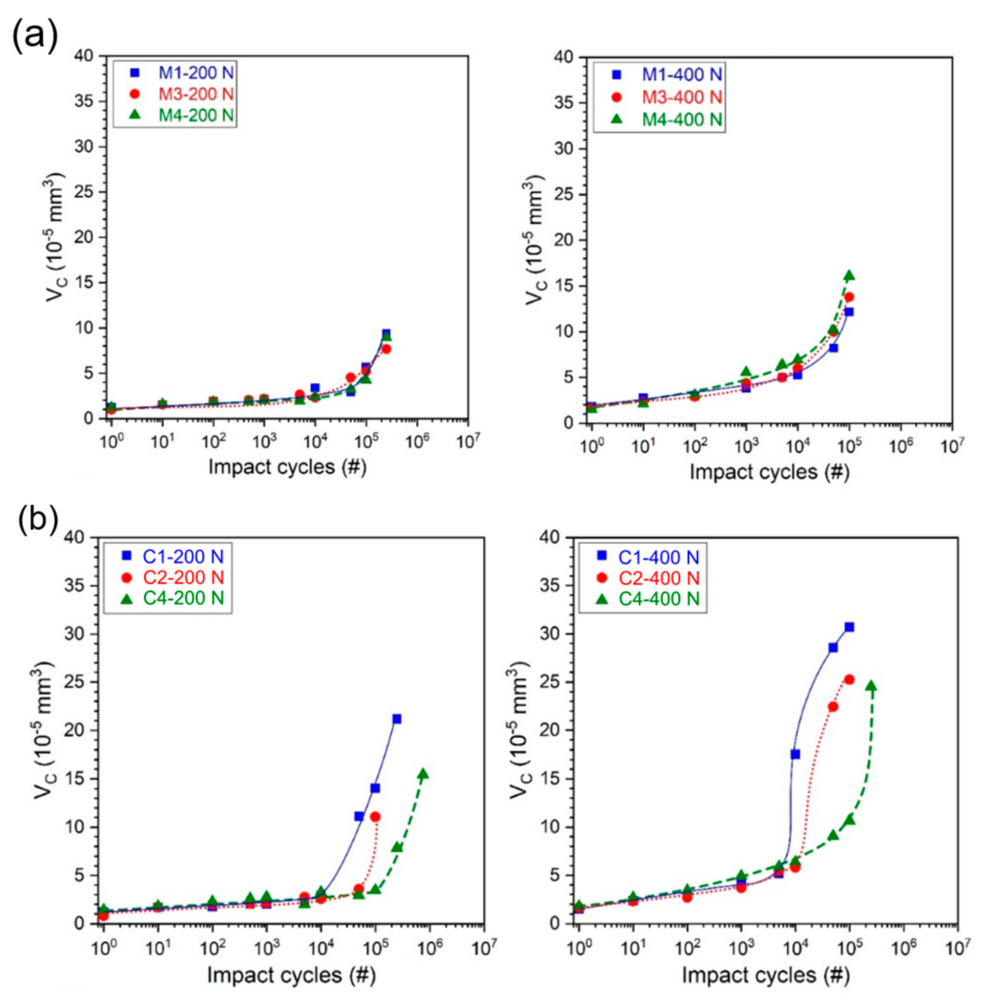
  • Zone I: With the first impacts, the VC increases mainly due to the substrate plastic deformation [38], whereas the coating is elastically stressed [13]. As the extent of plastic deformation increases after every successive impact, the contact pressure rapidly decreases because of the increasing contact area between the impact ball and sample. If the coating cannot follow the strain induced by substrate deformation, the cracks are initiated to reduce stress [39].
  • Zone II: When the contact pressure decreases to the substrate yield point, the plastic deformation of the substrate is suppressed and the system transits into zone II, the “zero impact wear” stage [11]. The VC remains almost constant with increasing impact cycles [11,38]. In this zone, the contact pressure is almost stable, and the cyclic impact loads provide the stress necessary for crack nucleation, propagation, and coalescence [40]. Accordingly, the edge cracks initiate from the coating surface and propagate downwards towards the interface, while the lateral cracks initiate at the substrate/coating interface and propagate upward into the coating [38,40].
  • Zone III: After the zero-impact wear stage, the coating/substrate system cannot accumulate more energy received from an impact indenter; hence the system transits into zone III. In this stage, the cohesive failure of the film and/or adhesive failure at the interface occurs, and the VC increases rapidly with increasing impact cycles [38].
Impact lifetime, the critical number of impacts NC, was evaluated as a transition between zone II and zone III. If this transition is uncertain, the NC is specified using the study of the impact crater profiles and microphotographs (delamination) or by other dependencies of the impact crater parameters on the number of impact cycles [37].

3. Results and Discussion

3.1. Coating Structure and Mechanical Properties

This sub-chapter will summarize the main conclusions from our previous work about the connection between deposition parameters, coating structure, and mechanical properties of the studied AlCrN coatings [14]. For a detailed description of the deposition process characterization and the coating structure and mechanical properties evaluation, please see ref. [14].
Two series of AlCrN coatings were deposited by an industrial magnetron sputtering system with the device for regulation of plasma ionisation, SCIL® technology. The coatings were prepared with the well-known average ion energy per deposited atom (Ed) ranging from 0.15 to 1.17 keV/atom and its components, ion energy Ei and ion-deposition flux ratio (Ji/Jd) ranging from ~3 to ~12. It was shown that the coating deposited in the metallic mode (M-coatings) with a lower Ji/Jd ratio and lower Ed exhibited a wurtzite hexagonal structure (h-AlN). The coatings deposited in the poisoned mode (C-coatings) with a lower deposition flux and thus higher Ji/Jd ratio showed a NaCl-type cubic structure (c-(Al,Cr)N). A study of the cross-section of the coatings revealed that an increase of the Ed led to densification of both hexagonal and cubic structures. All the studied coatings exhibited almost the same chemical composition, regardless of their deposition conditions [14]. This observation was in contrary to another metal–chromium-based coating, Ti-Cr-O, which showed changes in chemical composition in the metallic and compound regimes [41].
The effective elastic modulus of the coatings was strongly structure-dependent; however, no dependency on the Ed was observed. The E modulus of the M-coatings was ~300 GPa, while the modulus of C-coatings was ~480 GPa. On the other hand, the hardness and residual macro-stress of the coatings were strongly linearly dependent on the Ed, regardless of the structure of the coatings. Here, the high-energy Ed causes the coating densification and the formation of lattice defects, which causes increase of the residual stress, as well as compressive stress hardening.
For both scratch adhesion analysis and dynamic impact testing, three AlCrN coatings were chosen from each set. Table 1 summarizes the mechanical properties, structure, and thickness of those chosen coatings. All the properties are from ref. [14]; only those important for later discussion were selected.

3.2. Adhesion

Scratch adhesion generally depends on the thickness of the tested coating and on the coating’s hardness [42,43]. The AlCrN M-coatings exhibited thicknesses in the range of 5.1–5.4 µm. On the other hand, the C-coatings exhibited a thickness of 2.6–2.7 µm. Thus, the scratch adhesion will be discussed separately for the M-coatings’ case and for the C-coatings.
The scratch paths of the M-coatings are compared in Figure 1. All the M-coatings exhibited chipping failure mode [42,43,44]. As one can see, none of the M-coatings exhibited cracking. Thus, the LC1 value was not measured for any of the coatings. The best scratch adhesion connected with the LC2 value of 63.5 N exhibited by the M1 coating. On the other hand, the coating M4 exhibited the lowest value of LC2, 40.4 N. Since no complete coating failure was observed to be connected with delamination, the value of LC3 was higher than 100 N for each of the M-coatings. Adhesion values LC1, LC2, and LC3 of the M-coatings are summarized in Table 2.
The scratch paths of the C-coatings are compared in Figure 2. The scratch path of the C1 coating showed cracking in front of the scratch path. This was probably caused by the buckling failure mode [43]. The first cracks emerged at the load of 82.2 N (not clearly visible in Figure 2), and the failure connected with the LC2 came at 83.8 N. The C2 and C4 coatings exhibited a combination of the buckling and chipping scratch failure modes [42,43,44]. Neither coating exhibited cracking and failure related to the LC2 loads at 58.4 N (C4) and 45.0 N (C2). Adhesion values LC1, LC2, and LC3 of the M-coatings are summarized in Table 3.
Bull connected scratch test failure modes with the coatings and substrate hardness [44]. In the case of the same coating thickness and hard substrate, chipping failure mode is characteristic for coatings with higher hardness than the coatings that exhibit buckling failure mode [44]. On the other hand, C-coatings exhibited hardness that was the same or slightly higher than the M-coatings. Thus, the reasons for different failure modes could be (1) different thicknesses between C and M-coatings; (2) a huge difference between the Eeff modulus of the WC-Co substrate (~500 GPa) and M-coatings (~300 GPa), while C-coatings (~480 GPa) have a similar Eeff to WC-Co; and/or (3) different structures—the M-coatings are more brittle due to their dominant hexagonal structure (covalent + ionic bonding between atoms) than the C-coatings with a dominant cubic structure (covalent + metallic bonding between atoms).
The case apart from the rest was coating C1 with considerably better adhesion than the other coatings. Burnett et al. showed that coatings with lower hardness and higher residual stress exhibit higher adhesion than coatings with the same composition, structure, and thickness [42]. As was shown in sub-chapter 3.1., this is the case of the C1 coating.
Adhesion of the coatings expressed as a critical force in the scratch test depends on many factors, including the material of the substrate. Thus, comparisons of scratch adhesion data with the literature are limited because most authors have studied the scratch adhesion of AlCrN coatings on various types of steel substrates [31,32,45]. In addition, scratch adhesion depends on the mechanical properties of the coating, namely, its microstructure and chemical composition [8]. For example, Polcar et al. determined the scratch adhesion of a Cr-Al-N coating deposited by cathodic arc on a WC/Co substrate as LC2 = 70 N [46]; the coating exhibited a similar microstructure and thickness to our C2 coating (LC2 = 45 N), but the higher amount of Cr and lower amount of metal phase in Polcar’s coating likely resulted in a different hardness and modulus, and thus a different adhesion, than in our case. Wang et al. investigated a coating with a similar microstructure to our M3 coating and determined its LC2 to be 44 N [47]; the difference in adhesion (LC2(M3) = 56.6 N) may be due to the lower amount of metal phase in our coating.

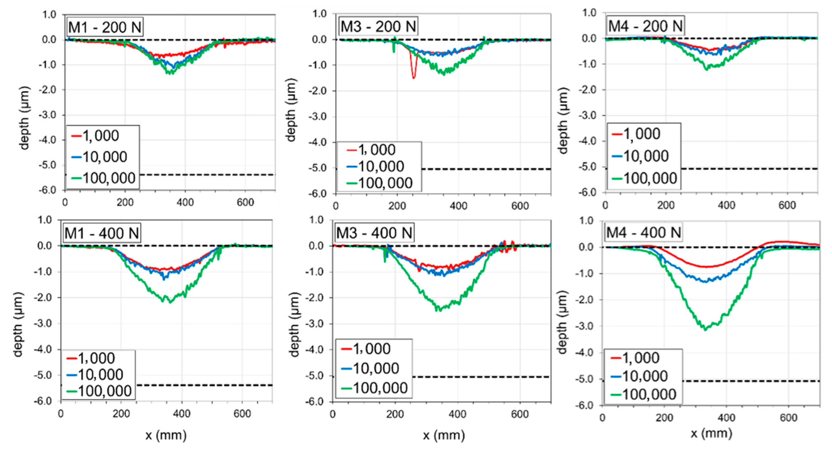
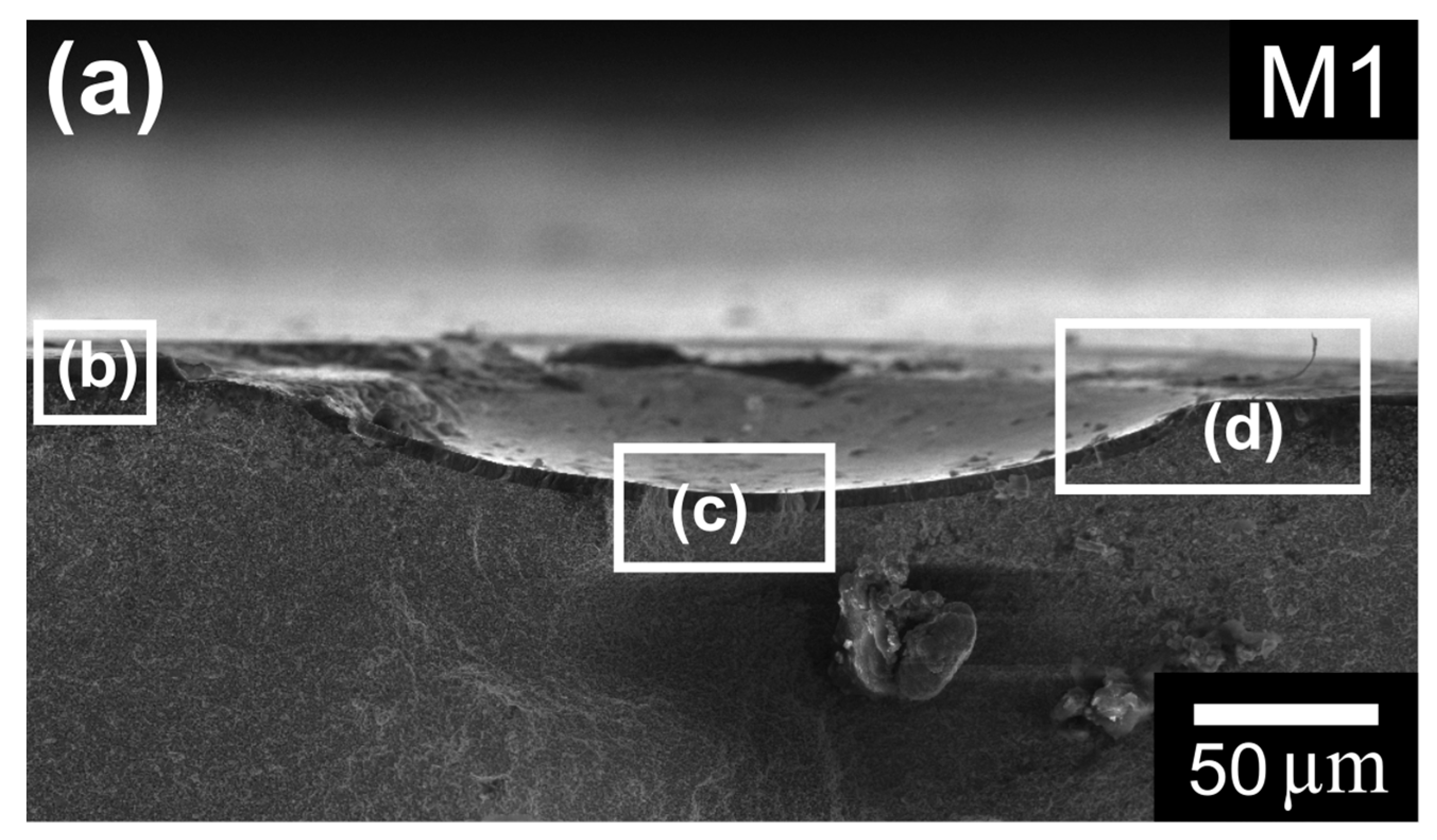
3.3. Dynamic Impact Resistance

The actual loading curves of the selected AlCrN coatings at applied impact loads of 200 N and 400 N are shown in Figure 3. The transition between zone I and zone II is not clearly visible in all curves. However, after reaching a critical number of impacts, the volume of the impact craters increased rapidly, and the loading curve reached zone III. The NC values were calculated from the loading curves and plotted in Figure 4a. For each impact load, the M-coatings exhibited an identical loading curve and subsequently similar NC value regardless of their deposition condition, indicating similar impact resistance. However, the C-coatings showed different impact resistance depending on their deposition conditions. Accordingly, the coatings deposited with higher Ed exhibited higher NC values and better impact resistance.
The measured crater volume after 105 loading cycles for selected coatings at different impact loads is shown in Figure 4b. These values were used as another measure for evaluating the impact resistance of coatings. This figure indicates that the VC after 105 cycles in M-coatings was almost independent of Ed, while increasing Ed led to an enhancement in the impact resistance of C-coatings. This result is in good agreement with the obtained result from the NC parameter.
In addition, Figure 5 shows optical microphotographs corresponding to the residual impact impression after 105 loading cycles at various force amplitudes for selected AlCrN coatings. For the M-coatings, no severe damages such as delamination, cohesive peeling, or adhesion peeling were observed at both applied impact loads, indicating good impact resistance of the coatings. In this case, the residual imprint was developed because of the permanent substrate plastic deformation, whereas the coating deforms purely elastically and fully recovers by the end of each load cycle [12].
However, the impact behaviour of C-coatings depended on the deposition conditions. Accordingly, the C1 coating applied at a low Ed showed the worst impact resistance and severe cracking occurred at both applied forces. The impact resistance of the coatings was improved by increasing Ed, the extent of spalling significantly decreased in the C2 coating, and finally, the C4 coating deposited at the highest Ed exhibited an imprint with no sign of severe failure comparable to the M-coatings. These results can be explained by the role of H/E and H3/E2 parameters in the impact resistance of coatings. The H/E parameter is related to the wear resistance [37], while H3/E2 is often associated with resistance to the plastic deformation [48] or fracture resistance [49] of materials. As shown in Figure 4, an increase in the impact resistance of C-coatings can be well-correlated with an increase in both the H/E and H3/E2 parameters. Beake et al. [50] showed that increasing the H3/E2 parameters improves the impact resistance of AlTiN coatings by providing better load support.
In addition, the different impact behaviour of M-coatings compared to C-coatings can be related to the difference in their thicknesses. Accordingly, a sufficiently thick coating acts as a physical barrier and protects the substrate from impact loading, whereas a thin coating transfers the stress field generated by the impact to the substrate, leading to large plastic deformation of the substrate. Hard and often brittle coatings cannot accommodate the resulting plastic deformation; therefore, a network of cracks is formed, which reduces the stress in the coating and can lead to failure [39].
To gain further insight, Figure 6 shows the transverse profiles of the impact craters after 103, 104, and 105 loading cycles at both impact loads. The dashed grey line indicates the coating surface and the coating/substrate interface. At a constant impact loading, the depth of the impact craters after 103 loading cycles is the same for all coatings, indicating the existence of identical plastic deformation in their substrates. However, the amount of induced strain in the coatings is inversely related to the coating thickness. As mentioned earlier, by increasing the impact cycles (to 104 and 105 cycles), the crack propagation and coalescence can lead to cracking and severe coating failure. Accordingly, a higher fracture resistance (H3/E2) could inhibit crack propagation, leading to a longer coating lifetime. Consequently, the combination of higher H3/E2 and greater thickness is advantageous to provide greater load support, leading to higher NC and better impact resistance.
A scanning electron microscope image of a cross-section of sample M1 is shown in Figure 7. The depicted impact crater was created by 104 impact cycles with an impact load of 400 N. The entire impact crater is shown in Figure 7a. The depth of the depicted crater was ~15 µm and the thickness of the M1 coating can be estimated to be approximately 5 µm from Figure 7b. Figure 7c shows the plastically deformed WC-Co substrate and the deformed coating. The rim of the impact crater is shown in detail in Figure 7d. Figure 7d is only schematically indicated in Figure 7a; Figure 7d was taken from a different cross-sectional view. The thickness of the observed coating decreased towards the crater rim, where the stresses are most intense during impact tests [51,52]. This stress caused both microcracks and delamination at the impact crater rim, which can be seen in some impact craters in Figure 5.
In this study, the C-coatings experienced much more strain and therefore exhibited more cracks compared to the M-coatings. This may explain the failure of the C1 and C2 coatings before 105 cycles (Figure 5 and Figure 6). However, the C4 coating exhibited a high impact resistance, as did the M-coatings, as it had the highest H3/E2 value despite having the smallest thickness. In addition, the M-coatings with higher thickness exhibited low deformation due to their high thickness (approximately twice the thickness of the C-coatings) and approximately 10% higher H/E ratio, thus having better wear resistance. It appears that 105 load cycles, even at the impact force of 400 N, were not sufficient to cause significant failure in the M-coatings and may have only increased the crack density in the coatings. The observed differences in the crater depths of the M-coatings can be attributed to differences in their adhesion strength, as they exhibited chipping failure during the scratch test. Accordingly, the critical load (LC2), i.e., the value of the scratch load when a coating fails, was measured to be 63.5 N, 56.6 N, and 40.4 N for the M-coatings, respectively.

4. Conclusions

Two sets of the AlCrN coatings were sputtered by an industrial magnetron sputtering system with control of the plasma ionization using the technology SCIL® (Sputter Coatings Induced by Lateral Glow Discharge).
Each set of coatings was deposited in a different reactive mode, metallic (M-coatings) and poisoned (C-coatings), and the average ion energy per deposited atom Ed resulted in different dominant structures—h-AlN and c-Cr(Al)N, respectively. The adhesion of the coatings to the WC-Co substrate was measured by laboratory scratch test, and a dynamic impact tester with impact loads of 200 N and 400 N was used for testing the coating’s dynamic impact resistance. The results can be summarized in these points:
-
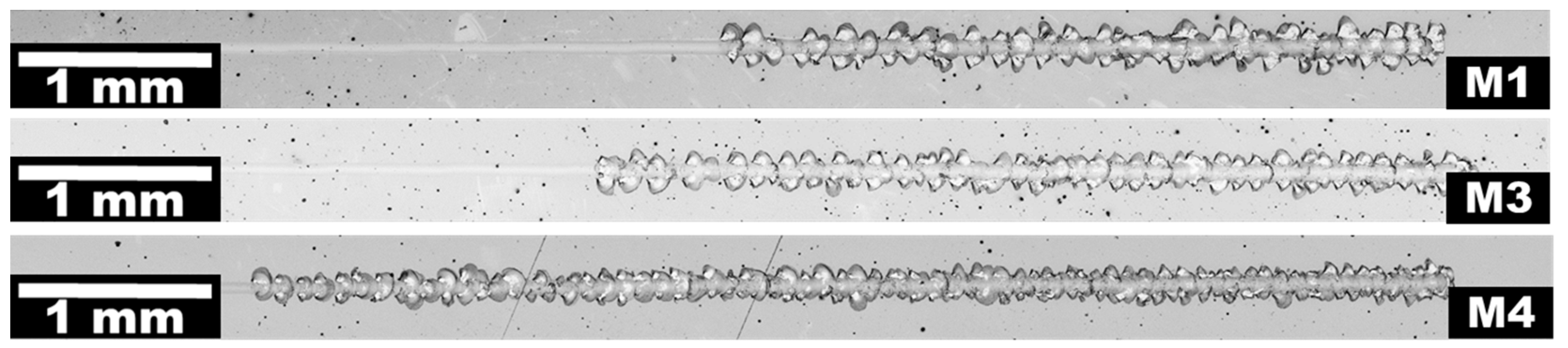
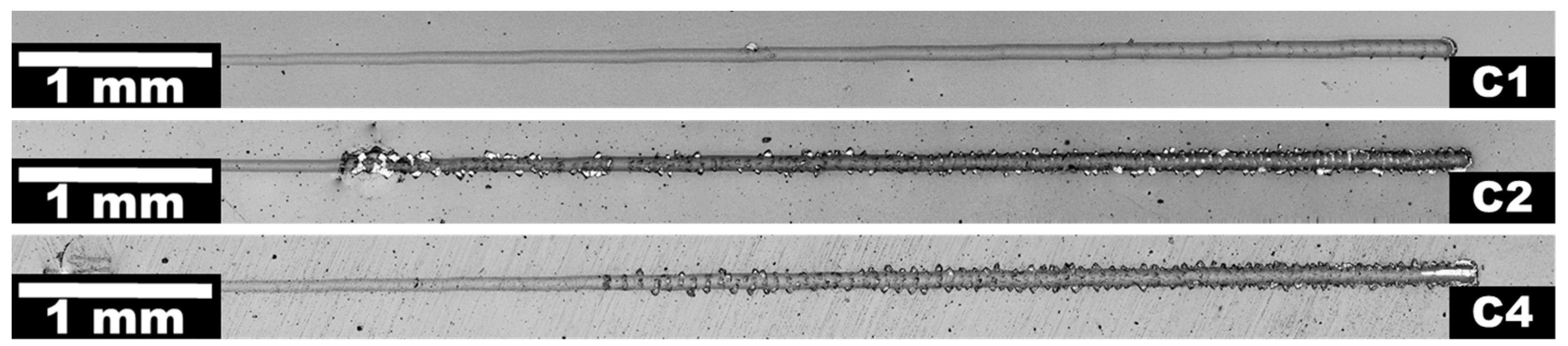
The M-coatings exhibited chipping scratch failure mode, typical for hard coating on the hard substrate. The C-coatings exhibited chipping/buckling scratch failure mode, probably due to their lower thickness.
-
The best adhesion was exhibited by the C-coating with the dominant c-Cr(Al)N phase, the lowest hardness, and the lowest compressive residual stress.
-
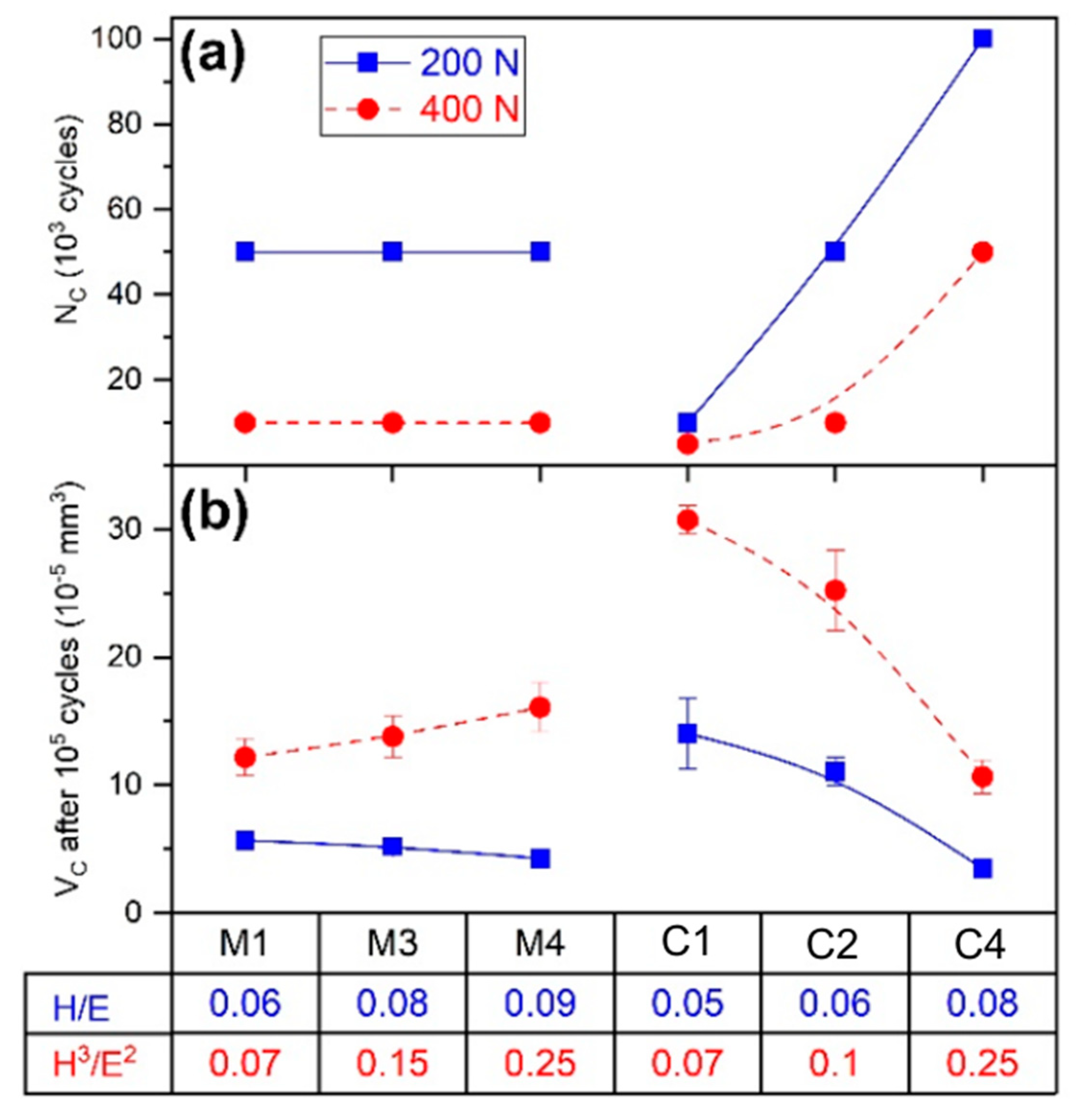
The critical number of impacts for the M-coatings was the same, independent of the deposition parameters. The critical load of the C-coatings strongly depended on Ed.
-
The C-coatings deposited with higher Ed exhibited a higher critical number of impacts and better impact resistance.
-
Since both series have the same H3/E2 ratio, the better impact resistance of the M-coatings was probably caused by the effects of thickness and wear resistance. The M-coatings exhibited an H/E ratio approximately 10% higher than the C-coatings and thus had better wear resistance. In addition, they were approximately two times thicker, so they better-protected the substrate from plastic deformation.

Author Contributions

R.Ž., D.K., A.L. and H.B. prepared tested coatings and studied deposition process; P.S. and P.V. analysed their structure and phase composition; P.K. analysed coatings adhesion; J.D. and T.F. analysed coatings using dynamic impact test; M.A. investigated coatings using SEM; M.A., J.D. and R.Ž. wrote the paper. All authors have read and agreed to the published version of the manuscript.

Funding

This research was supported by the project LM2018097 funded by the Ministry of Education Youth and Sports of the Czech Republic and by the institutional support RVO:68081731.

Institutional Review Board Statement

Not applicable.

Informed Consent Statement

Not applicable.

Data Availability Statement

Not applicable.

Conflicts of Interest

The authors declare no conflict of interest.

References

  1. Podgornik, B.; Sedlaček, M.; Čekada, M.; Jacobson, S.; Zajec, B. Impact of fracture toughness on surface properties of PVD coated cold work tool steel. Surf. Coat. Technol. 2015, 277, 144–150. [Google Scholar] [CrossRef]
  2. Teixeira, V. Residual stress and cracking in thin PVD coatings. Vacuum 2002, 64, 393–399. [Google Scholar] [CrossRef]
  3. Lind, L.; Peetsal, P.; Sergejev, F. Wear of different PVD coatings at industrial fine-blanking field tests. Mater. Sci. 2015, 21, 343–348. [Google Scholar] [CrossRef] [Green Version]
  4. Daniel, J.; Žemlička, R.; Grossman, J.; Lümkemann, A.; Tapp, P.; Galamand, C.; Fořt, T. Comparison of Lifetime of the PVD Coatings in Laboratory Dynamic Impact Test and Industrial Fine Blanking Process. Materials 2020, 13, 2154. [Google Scholar] [CrossRef]
  5. Sergejev, F.; Peetsalu, P.; Sivitski, A.; Saarna, A.M.; Adoberg, E. Surface fatigue and wear of PVD coated punches during the fine blanking operation. Eng. Fail. Anal. 2001, 18, 1689–1697. [Google Scholar] [CrossRef]
  6. Musil, J. Hard and superhard nanocomposite coatings. Surf. Coating. Technol. 2000, 125, 322–330. [Google Scholar] [CrossRef]
  7. Bouzakis, K.-D.; Michailidis, N.; Skordaris, G.; Bouzakis, E.; Biermann, D.; M’Saoubi, R. Cutting with Coated Tools: Coating Technologies, Characterization Methods and Performance Optimization. CIRP Ann.—Manuf. Technol. 2012, 61, 703–723. [Google Scholar] [CrossRef]
  8. Vetter, J.; Eriksson, A.O.; Reiter, A.; Derflinger, V.; Kalss, W. Quo Vadis: AlCr-Based Coatings in Industrial Applications. Coatings 2021, 11, 344. [Google Scholar] [CrossRef]
  9. Knotek, O.; Bosserhoff, B.; Schrey, A.; Leyendecker, T.; Lemmer, O.; Esser, S.A. A new technique for testing the impact load of thin films: The coating impact test. Surf. Coat. Technol. 1992, 54, 102–107. [Google Scholar] [CrossRef]
  10. Sobota, J.; Grossman, J.; Buršíková, V.; Dupák, L.; Vyskočil, J. Evaluation of hardness, tribological behaviour and impact load of carbon-based hard composite coatings exposed to the influence of humidity. Diam. Rel. Mat. 2011, 20, 596–599. [Google Scholar] [CrossRef]
  11. Engel, P.A.; Yang, Q. Impact wear of multiplated electrical contacts. Wear 1995, 181–183, 730–742. [Google Scholar] [CrossRef]
  12. Bouzakis, K.D.; Maliaris, G.; Makrimallakis, S. Strain rate effect on the fatigue failure of thin PVD coatings: An investigation by a novel impact tester with adjustable repetitive force. Int. J. Fatigue 2012, 44, 89–97. [Google Scholar] [CrossRef]
  13. Žemlička, R.; Souček, P.; Vogl, P.; Jílek, M.; Buršíková, V.; Vašina, P.; Pei, Y.T. On the significance of running-in of hard nc-TiC/aC: H coating for short-term repeating machining. Surf. Coat. Technol. 2017, 315, 17–23. [Google Scholar] [CrossRef]
  14. Žemlička, R.; Alishahi, M.; Jílek, M.; Souček, P.; Daniel, J.; Kluson, J.; Bolvardi, H.; Lümkemann, A.; Vašina, P. Enhancing mechanical properties and cutting performance of industrially sputtered AlCrN coatings by inducing cathodic arc glow discharge. Surf. Coat. Technol. 2021, 422, 127563. [Google Scholar] [CrossRef]
  15. Lin, J.; Mishra, B.; Moore, J.J.; Sproul, W.D. Microstructure, mechanical and tribological properties of Cr1−xAlxN films deposited by pulsed-closed field unbalanced magnetron sputtering (P-CFUBMS). Surf. Coat. Technol. 2006, 201, 4329–4334. [Google Scholar] [CrossRef]
  16. Mayrhofer, P.H.; Music, D.; Reeswinkel, T.; Fuß, H.G.; Schneider, J.M. Structure, elastic properties and phase stability of Cr1–xAlxN. Acta Mater. 2008, 56, 2469–2475. [Google Scholar] [CrossRef]
  17. Carreira, L.A.; de Almeida, G.; Haring, G.M. Surface integrity of machined AISI D2 steel and its effect on the adhesion of a PVD-AlCrN coating. Int. J. Adv. Manuf. Technol. 2021, 112, 2705–2715. [Google Scholar] [CrossRef]
  18. Willmann, H.; Mayrhofer, P.H.; Persson, P.O.Å.; Reiter, A.E.; Hultman, L.; Mitterer, C. Thermal stability of Al–Cr–N hard coatings. Scr. Mater. 2006, 54, 1847–1851. [Google Scholar] [CrossRef]
  19. Mo, J.L.; Zhu, M.H. Sliding tribological behavior of AlCrN coating. Tribol. Int. 2008, 41, 1161–1168. [Google Scholar] [CrossRef]
  20. Gong, M.; Chen, J.; Deng, X.; Wu, S. Sliding wear behavior of TiAlN and AlCrN coatings on a unique cemented carbide substrate. Int. J. Refract. Met. Hard Mater. 2017, 69, 209–214. [Google Scholar] [CrossRef]
  21. Reiter, A.E.; Derflinger, V.H.; Hanselmann, B.; Bachmann, T.; Sartory, B. Investigation of the properties of Al1−xCrxN coatings prepared by cathodic arc evaporation. Surf. Coat. Technol. 2005, 200, 2114–2122. [Google Scholar] [CrossRef]
  22. Jäger, N.; Klima, S.; Hruby, H.; Julin, J.; Burghammer, M.; Keckes, J.F.; Mitterer, C.R.; Daniel, R. Evolution of structure and residual stress of a fcc/hex-AlCrN multi-layered system upon thermal loading revealed by cross-sectional X-ray nano-diffraction. Acta Mater. 2019, 162, 55–66. [Google Scholar] [CrossRef]
  23. Sabitzer, C.; Paulitsch, J.; Kolozsvári, S.; Rachbauer, R.; Mayrhofer, P.H. Influence of bias potential and layer arrangement on structure and mechanical properties of arc evaporated Al–Cr–N coatings. Vacuum 2014, 106, 49–52. [Google Scholar] [CrossRef]
  24. Banko, L.; Ries, S.; Grochla, D.; Arghavani, M.; Salomon, S.; Pfetzing-Micklich, J.; Kostka, A.; Rogalla, D.; Schulze, J.; Awakowicz, P.; et al. Effects of the ion to growth flux ratio on the constitution and mechanical properties of Cr1–x-Alx-N thin films. ACS Comb. Sci. 2019, 21, 782–793. [Google Scholar] [CrossRef]
  25. Tang, J.F.; Lin, C.Y.; Yang, F.C.; Tsai, Y.J.; Chang, C.L. Effects of nitrogen-argon flow ratio on the microstructural and mechanical properties of AlCrN coatings prepared using high power impulse magnetron sputtering. Surf. Coat. Technol. 2020, 386, 125484. [Google Scholar] [CrossRef]
  26. Iram, S.; Cai, F.; Wang, J.; Zhang, J.; Liang, J.; Ahmad, F.; Zhang, S. Effect of Addition of Mo or V on the Structure and Cutting Performance of AlCrN-Based Coatings. Coatings 2020, 10, 298. [Google Scholar] [CrossRef] [Green Version]
  27. Chen, W.; Hu, T.; Hong, Y.; Zhang, D.; Meng, X. Comparison of microstructures, mechanical and tribological properties of arc-deposited AlCrN, AlCrBN and CrBN coatings on Ti-6Al-4V alloy. Surf. Coat. Technol. 2020, 404, 126429. [Google Scholar] [CrossRef]
  28. Hosokawa, A.; Saito, R.; Ueda, T. Milling characteristics of VN/AlCrN-multilayer PVD coated tools with lubricity and heat resistance. CIRP Ann. 2020, 69, 49–52. [Google Scholar] [CrossRef]
  29. Gao, Y.; Cai, F.; Zhang, L.; Zhang, S. Structure optimization and cutting performance of gradient multilayer AlCrSiN films with ion source etching pretreatment. J. Mater. Eng. Perform. 2020, 29, 997–1006. [Google Scholar] [CrossRef]
  30. Cai, F.; Gao, Y.; Zhang, S.; Zhang, L.; Wang, Q. Gradient architecture of Si containing layer and improved cutting performance of AlCrSiN coated tools. Wear 2019, 424–425, 193–202. [Google Scholar] [CrossRef]
  31. Ramírez-Reyna, F.O.; Rodríguez-Castro, G.A.; Figueroa-López, U.; Morón, R.C.; Arzate-Vázquez, I.; Meneses-Amador, A. Effect of nitriding pretreatment on adhesion and tribological properties of AlCrN coating. Mater. Lett. 2021, 284, 128931. [Google Scholar] [CrossRef]
  32. Ballesteros-Arguello, A.; Ramírez-Reyna, F.O.; Rodríguez-Castro, G.A.; Meneses-Amador, A.; Fernández-Valdés, D.; Reyes-Carcano, O. Experimental and numerical evaluation of the contact fatigue resistance of AlCrN, FexN and AlCrN/FexN coatings on AISI 4140 steel. Surf. Coat. Technol. 2021, 423, 127620. [Google Scholar] [CrossRef]
  33. Bobzin, K.; Kalscheuer, C.; Carlet, M.; Tayyab, M. Influence of Aluminum Content on the Impact Fatigue of HPPMS CrAlN Coatings on Tool Steel. Phys. Mesomech. 2021, 24, 625–632. [Google Scholar] [CrossRef]
  34. Mo, J.L.; Zhu, M.H.; Leyland, A.; Matthews, A. Impact wear and abrasion resistance of CrN, AlCrN and AlTiN PVD coatings. Surf. Coat. Technol. 2013, 215, 170–177. [Google Scholar] [CrossRef]
  35. Hybrid LACS Technology. Available online: https://www.platit.com/en/coating-know-how/coating-technologies/ (accessed on 27 January 2023).
  36. ASTM C1624-05; Standard Test Method for Adhesion Strength and Mechanical Failure Modes of Ceramic Coatings by Quantitative Single Point Scratch Testing. ASTM International Standards: West Conshohocken, PA, USA, 2005. [CrossRef]
  37. Daniel, J.; Souček, P.; Grossman, J.; Zábranský, L.; Bernátová, K.; Buršíková, V.; Fořt, T.; Vašina, P.; Sobota, J. Adhesion and dynamic impact wear of nanocomposite TiC-based coatings prepared by DCMS and HiPIMS. Int. J. Refract. Met. Hard Mater. 2020, 86, 105123. [Google Scholar] [CrossRef]
  38. Shi, X.; Beake, B.D.; Liskiewicz, T.W.; Chen, J.; Sun, Z. Failure mechanism and protective role of ultrathin ta-C films on Si (100) during cyclic nano-impact. Surf. Coat. Technol. 2019, 364, 32–42. [Google Scholar] [CrossRef]
  39. Abdollah, M.F.B.; Yamaguchi, Y.; Akao, T.; Inayoshi, N.; Miyamoto, N.; Tokoroyama, T.; Umehara, N. Deformation–wear transition map of DLC coating under cyclic impact loading. Wear 2012, 274–275, 435–441. [Google Scholar] [CrossRef]
  40. Zha, X.; Jiang, F.; Xu, X. Investigating the high frequency fatigue failure mechanisms of mono and multilayer PVD coatings by the cyclic impact tests. Surf. Coat. Technol. 2018, 344, 689–701. [Google Scholar] [CrossRef]
  41. Bahrami, A.; Delgado, A.; Onofre, C.; Muhl, S.; Rodil, S.E. Structure, mechanical properties and corrosion resistance of amorphous Ti-Cr-O coatings. Surf. Coat. Technol. 2019, 374, 690–699. [Google Scholar] [CrossRef]
  42. Burnett, P.J.; Rickerby, D.S. The relationship between hardness and scratch adhesion. Thin Solid Film. 1987, 154, 403–416. [Google Scholar] [CrossRef]
  43. Bull, S.J. Failure modes in scratch adhesion testing. Surf. Coat. Technol. 1991, 50, 25–32. [Google Scholar] [CrossRef]
  44. Bull, S.J. Failure mode maps in thin film scratch adhesion test. Tribol. Int. 1997, 30, 491–498. [Google Scholar] [CrossRef]
  45. Delgado, A.; Garcia-Zarco, O.; Restrepo, J.; Rodil, S.E. AlCrVN coatings deposited by cathodic arc: Friction and wear properties evaluated using reciprocating sliding test. Surf. Coat. Technol. 2022, 442, 128140. [Google Scholar] [CrossRef]
  46. Polcar, T.; Cavaleiro, A. High-temperature tribological properties of CrAlN, CrAlSiN and AlCrSiN coatings. Surf. Coat. Technol. 2011, 206, 1244–1251. [Google Scholar] [CrossRef]
  47. Wang, L.; Zhang, S.; Chen, Z.; Li, J.; Li, M. Influence of Deposition Parameters on Hard Cr-Al-N Coatings Deposited by Multi-Arc Ion Plating. Appl. Surf. Sci. 2012, 258, 3629–3636. [Google Scholar] [CrossRef]
  48. Leyland, A.; Matthews, A. On the significance of the H/E ratio in wear control: A nanocomposite coating approach to optimised tribological behaviour. Wear 2000, 246, 1–11. [Google Scholar] [CrossRef]
  49. Alishahi, M.; Mirzaei, S.; Souček, P.; Zábranský, L.; Buršíková, V.; Stupavská, M.; Peřina, V.; Balázsi, K.; Czigány, Z.; Vašina, P. Evolution of structure and mechanical properties of hard yet fracture resistant W-B-C coatings with varying C/W ratio. Surf. Coat. Technol. 2018, 340, 103–111. [Google Scholar] [CrossRef] [Green Version]
  50. Beake, B.D.; Isern, L.; Endrino, J.L.; Fox-Rabinovich, G.S. Micro-impact testing of AlTiN and TiAlCrN coatings. Wear 2019, 418–419, 102–110. [Google Scholar] [CrossRef] [Green Version]
  51. Qiu, L.S.; Zhu, X.D.; Lu, S.; He, G.Y.; Xu, K.W. Quantitative evaluation of bonding strength for hard coatings by interfacial fatigue strength under cyclic indentation. Surf. Coat. Technol. 2017, 315, 303–313. [Google Scholar] [CrossRef]
  52. Lamri, S.; Langlade, C.; Kermouche, G. Damage phenomena of thin hard coatings submitted to repeated impacts: Influence of the substrate and film properties. Mater. Sci. Eng. A 2013, 560, 296–305. [Google Scholar] [CrossRef]
Figure 1. Scratch paths of the M-coatings. In the picture, just final parts of the paths are compared; the paths are incommensurable in this picture.
Coatings 13 00515 g001
Figure 2. Scratch paths of the C-coatings. In the picture, just final parts of the paths are compared; the paths are incommensurable in this picture.
Coatings 13 00515 g002
Figure 3. Variation in residual impact crater volume (VC) as a function of impact cycles at various impact loads for selected AlCrN (a) M-coatings and (b) C-coatings.
Coatings 13 00515 g003
Figure 4. The critical number of impacts NC (a) and residual impact crater volume VC (b) after 105 load cycles. Comparison with H/E and H3/E2 values corresponding to samples.
Coatings 13 00515 g004
Figure 5. Optical micrographs of residual impact imprints at various impact loads for selected AlCrN coatings after 105 load cycles.
Coatings 13 00515 g005
Figure 6. Cross-section profiles of impact craters after different impact cycles on AlCrN coatings. Horizontal dashed grey lines denote the position of the surface of coatings and the coating/substrate interface.
Coatings 13 00515 g006aCoatings 13 00515 g006b
Figure 7. Cross-section of the M1 coating (a). Enlarged details of the coating itself (b), bottom of the residual impact (c), and the impact crater edge (d).
Coatings 13 00515 g007aCoatings 13 00515 g007b
Table 1. Structure, thickness, and mechanical properties of the AlCrN coatings. Ed denotes average ion energy per deposited atom, HUpl is universal plastic hardness, and Eeff is effective Young’s modulus. The letters “h” and “c” refer to the hexagonal h-AlN and cubic c-(Al,Cr)N phases, respectively.
CoatingEd (keV/Atom)StructureThickness (µm)HUpl (GPa)Eeff (GPa)Stress (GPa)
M10.15h5.418.3 ± 0.3301 ± 29−0.53
M30.34h + c5.023.4 ± 0.3297 ± 12−1.32
M40.56h + c5.129.2 ± 1.0313 ± 10−2.13
C10.32c2.724.1 ± 1.8456 ± 20−1.14
C20.52c2.728.7 ± 1.1483 ± 30−1.40
C41.17c2.638.7 ± 1.3479 ± 26−2.61
Table 2. Summary of the scratch adhesion values evaluated for the M-coatings.
SampleLC1 [N]LC2 [N]LC3 [N]
M1-63.5>100
M3-56.6>100
M4-40.4>100
Table 3. Summary of the scratch adhesion values evaluated for the C-coatings.
SampleLC1 [N]LC2 [N]LC3 [N]
C182.283.8>100
C2-45.0>100
C4-58.4>100
Disclaimer/Publisher’s Note: The statements, opinions and data contained in all publications are solely those of the individual author(s) and contributor(s) and not of MDPI and/or the editor(s). MDPI and/or the editor(s) disclaim responsibility for any injury to people or property resulting from any ideas, methods, instructions or products referred to in the content.

