
Characterization and Corrosion Properties of Fluoride Conversion Coating Prepared on AZ31 Magnesium Alloy

 , , , and
Abstract
:1. Introduction
2. Materials and Methods
2.1. Experimental Material
2.2. Characterization of the Base Material Microstructure
2.3. Preparation of the Fluoride Conversion Coating
2.4. Coatings Surface Morphologies and Cross-Section Characterization
2.5. Electrochemical Corrosion Tests
2.6. Immersion Tests
3. Results and Discussion
3.1. Microstructural Analysis of Base Material
3.2. Fluoride Conversion Coating Characterization
3.3. Electrochemical Corrosion Tests
3.3.1. Potentiodynamic Polarization Tests
3.3.2. Electrochemical Impedance Spectroscopy
3.4. Immersion Tests
4. Conclusions
- The fluoride conversion coating was successfully created on AZ31 magnesium alloy surface in the case of all coating temperatures and times.
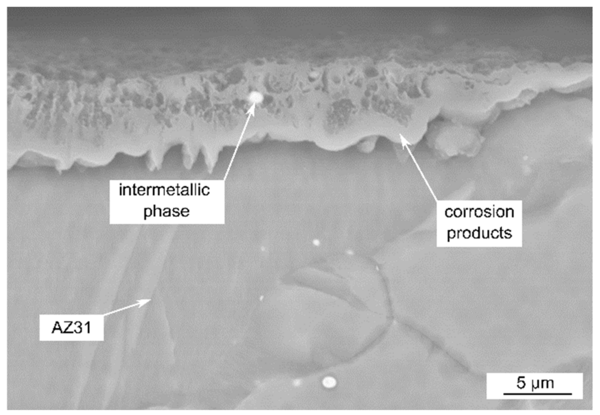
- Defects in form of pores were characteristic of the coatings. The EDS analysis revealed that, in the case of the coating time of 0.5 h and coating temperature of 430 °C, the pores went through the coating to the base material. In the case of longer coating time and higher temperature, regardless of the used time, the EDS analysis did not reveal the defects pass the coating and reach the base material.
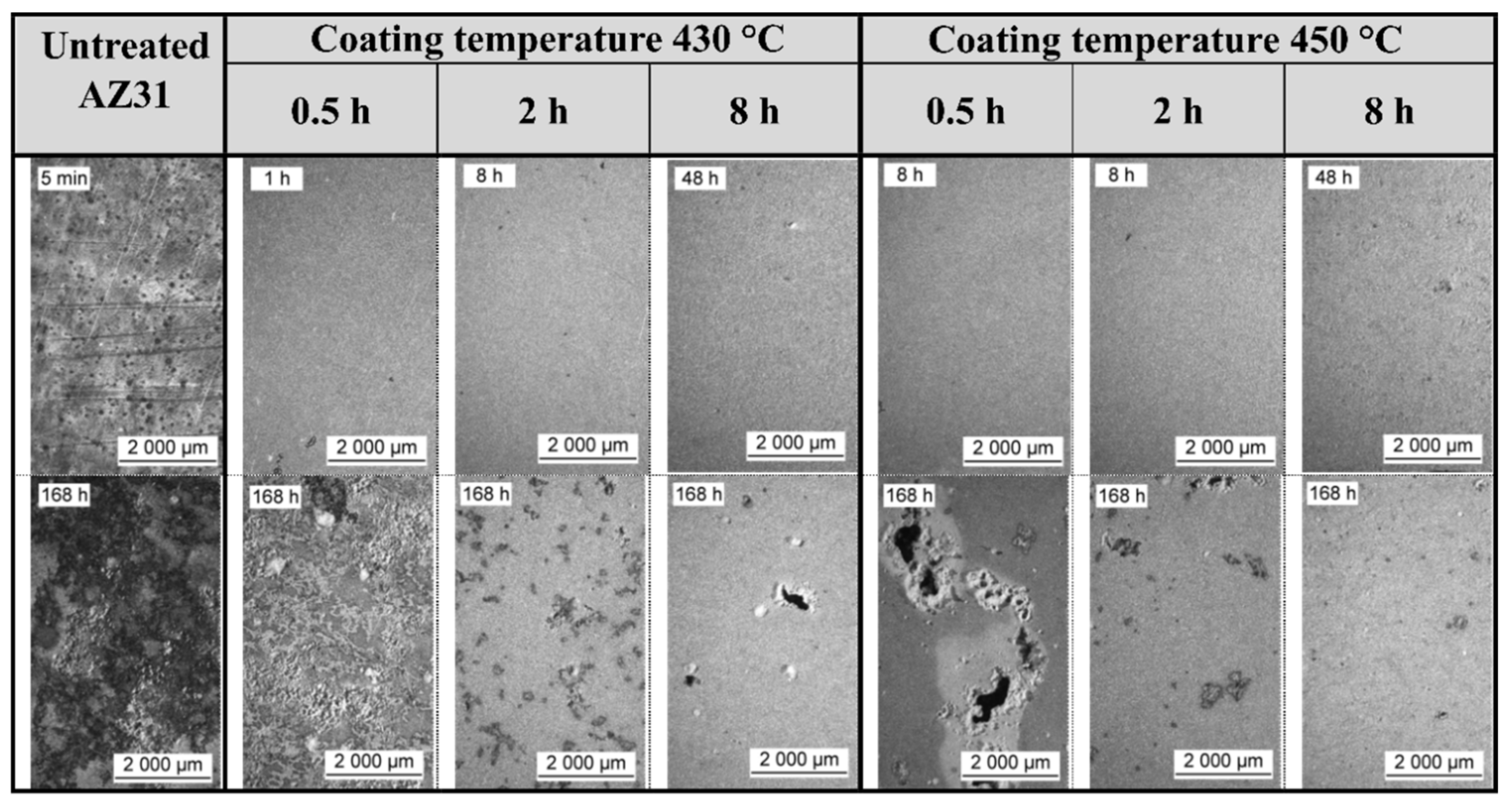
- The increase in the coating temperature and coating time resulted in higher coatings thicknesses and better corrosion resistance of the coated material in the SBF solution. The specimens treated for 8 h in Na[BF4] at 430 and 450 °C reached comparable and the best electrochemical corrosion properties from the tested specimens. However, the immersion test revealed that a higher coating temperature of 450 °C results in the creation of uniformly distributed places with smaller sizes of corrosion attacks on the coated surface, when compared to lower coating temperature 430 °C.
- The performed experiments support the assumption that the microstructure of the coated magnesium alloy can significantly affect corrosion resistance. The defects in the coating structure are most probably created due to the reaction of the AlxMny intermetallic phase with Na[BF4] molten salt and/or with product of its decomposition, BF3 compound, resulting in the creation of soluble Na3[AlF6] and AlF3 compounds which were removed from the coating during the removal of the secondary Na[MgF3] layer.
Author Contributions
Funding
Institutional Review Board Statement
Informed Consent Statement
Data Availability Statement
Conflicts of Interest
References
- Bagherifard, S.; Molla, M.F.; Kajanek, D.; Donnini, R.; Hadzima, B.; Guagliano, M. Accelerated biodegradation and improved mechanical performance of pure iron through surface grain refinement. Acta Biomater. 2019, 98, 88–102. [Google Scholar] [CrossRef] [PubMed]
- Zhou, H.; Liang, B.; Jiang, H.; Deng, Z.; Yu, K. Magnesium-based biomaterials as emerging agents for bone repair and regeneration: From mechanism to application. J. Magnes. Alloy. 2021. [Google Scholar] [CrossRef]
- Sajan, M.; Sampatirao, H.; Balasubramanian, R.; Nagumothu, R. Plasma Electrolytic Oxidation of AZ31 Magnesium Alloy Diffusion Bonded with Aluminium. Mater. Today Proc. 2021. [Google Scholar] [CrossRef]
- Mena-Morcillo, E.; Veleva, L.; Cerda-Zorrilla, M.; Soria-Castro, M.; Castro-Alcántara, J.C.; Canul-Puc, R.C. Development and assessment of a multifunctional chitosan-based coating applied on AZ31 magnesium alloy: Corrosion resistance and antibacterial performance against Klebsiella Pneumoniae. J. Magnes. Alloy. 2021. [Google Scholar] [CrossRef]
- Pokharel, D.B.; Wu, L.; Dong, J.; Yadav, A.P.; Subedi, D.B.; Dhakal, M.; Zha, L.; Mu, X.; Umoh, A.J.; Ke, W. Effect of glycine addition on the in-vitro corrosion behavior of AZ31 magnesium alloy in Hank’s solution. J. Mater. Sci. Technol. 2021, 81, 97–107. [Google Scholar] [CrossRef]
- Hiromoto, S.; Inoue, M.; Taguchi, T.; Yamane, M.; Ohtsu, N. In vitro and in vivo biocompatibility and corrosion behaviour of a bioabsorbable magnesium alloy coated with octacalcium phosphate and hydroxyapatite. Acta Biomater. 2015, 11, 520–530. [Google Scholar] [CrossRef]
- Duygulu, O.; Kaya, R.A.; Oktay, G.; Kaya, A.A. Investigation on the Potential of Magnesium Alloy AZ31 as a Bone Implant. Mater. Sci. Forum 2007, 546-549, 421–424. [Google Scholar] [CrossRef]
- Liu, D.; Yang, D.; Li, X.; Hu, S. Mechanical properties, corrosion resistance and biocompatibilities of degradable Mg-RE alloys: A review. J. Mater. Res. Technol. 2019, 8, 1538–1549. [Google Scholar] [CrossRef]
- Esmaily, M.; Svensson, J.E.; Fajardo, S.; Birbilis, N.; Frankel, G.S.; Virtanen, S.; Arrabal, R.; Thomas, S.; Johansson, L.G. Fundamentals and advances in magnesium alloy corrosion. Prog. Mater. Sci. 2017, 89, 92–193. [Google Scholar] [CrossRef]
- Avedesian, M.M.; Baker, H. ASM Specialty Handbook: Magnesium and Magnesium Alloys; ASM International: Materials Park, OH, USA, 1999; p. 15. [Google Scholar]
- Li, Y.; Wen, C.; Mushahary, D.; Sravanthi, R.; Harishankar, N.; Pande, G.; Hodgson, P. Mg-Zr-Sr alloys as biodegradable implant materials. Acta Biomater. 2012, 8, 3177–3188. [Google Scholar] [CrossRef]
- Yokel, R. The toxicology of aluminum in the brain: A review. NeuroToxicology 2000, 21, 813–828. [Google Scholar]
- Del Gaudio, C.; Bagalà, P.; Venturini, M.; Grandi, C.; Parnigotto, P.P.; Bianco, A.; Montesperelli, G. Assessment of in vitro temporal corrosion and cytotoxicity of AZ91D alloy. J. Mater. Sci. Mater. Electron. 2012, 23, 2553–2562. [Google Scholar] [CrossRef]
- Murni, N.; Dambatta, M.; Yeap, S.; Froemming, G.; Hermawan, H. Cytotoxicity evaluation of biodegradable Zn–3Mg alloy toward normal human osteoblast cells. Mater. Sci. Eng. C 2015, 49, 560–566. [Google Scholar] [CrossRef]
- Zberg, B.; Uggowitzer, P.J.; Löffler, J.F. MgZnCa glasses without clinically observable hydrogen evolution for biodegradable implants. Nat. Mater. 2009, 8, 887–891. [Google Scholar] [CrossRef]
- Sun, W.; Zhang, G.; Tan, L.; Yang, K.; Ai, H. The fluoride coated AZ31B magnesium alloy improves corrosion resistance and stimulates bone formation in rabbit model. Mater. Sci. Eng. C 2016, 63, 506–511. [Google Scholar] [CrossRef]
- Zhong, X.; Li, Q.; Hu, J.; Lu, Y. Characterization and corrosion studies of ceria thin film based on fluorinated AZ91D magnesium alloy. Corros. Sci. 2008, 50, 2304–2309. [Google Scholar] [CrossRef]
- Wang, J.; Tang, J.; Zhang, P.; Li, Y.; Wang, J.; Lai, Y.; Qin, L. Surface modification of magnesium alloys developed for bio-absorbable orthopedic implants: A general review. J. Biomed. Mater. Res. Part B 2012, 100B, 1691–1701. [Google Scholar] [CrossRef]
- Yan, T.; Tan, L.; Zhang, B.; Yang, K. Fluoride Conversion Coating on Biodegradable AZ31B Magnesium Alloy. J. Mater. Sci. Technol. 2014, 30, 666–674. [Google Scholar] [CrossRef]
- Narayanan, T.S.N.S.; Park, I.S.; Lee, M.H. Tailoring the composition of fluoride conversion coatings to achieve better corrosion protection of magnesium for biomedical applications. J. Mater. Chem. B 2014, 2, 3365. [Google Scholar] [CrossRef]
- Ye, X.-Y.; Chen, M.-F.; You, C.; Liu, D.-B. The influence of HF treatment on corrosion resistance and in vitro biocompatibility of Mg-Zn-Zr alloy. Front. Mater. Sci. China 2010, 4, 132–138. [Google Scholar] [CrossRef]
- Pan, C.-J.; Pang, L.-Q.; Hou, Y.; Lin, Y.-B.; Gong, T.; Liu, T.; Ye, W.; Ding, H.-Y. Improving Corrosion Resistance and Bio-compatibility of Magnesium Alloy by Sodium Hydroxide and Hydrofluoric Acid Treatments. Appl. Sci. 2016, 7, 33. [Google Scholar] [CrossRef] [Green Version]
- Tian, P.; Peng, F.; Wang, N.; Liu, X. Corrosion behavior and cytocompatibility of fluoride-incorporated plasma electrolytic oxidation coating on biodegradable AZ31 alloy. Regen. Biomater. 2016, 4, 1–10. [Google Scholar] [CrossRef] [PubMed] [Green Version]
- Yamamoto, A.; Terawaki, T.; Tsubakino, H. Microstructures and Corrosion Properties on Fluoride Treated Magnesium Alloy. Mater. Trans. 2008, 49, 1042–1047. [Google Scholar] [CrossRef] [Green Version]
- Fintová, S.; Drábiková, J.; Pastorek, F.; Tkacz, J.; Kuběna, I.; Trško, L.; Hadzima, B.; Minda, J.; Doležal, P.; Wasserbauer, J.; et al. Improvement of electrochemical corrosion characteristics of AZ61 magnesium alloy with unconventional fluoride conversion coatings. Surf. Coat. Technol. 2019, 357. [Google Scholar] [CrossRef]
- Ohse, T.; Tsubakino, H.; Yamamoto, A. Surface Modification on Magnesium Alloys by Coating with Magnesium Fluorides. Mater. Sci. Forum 2005, 2005, 505–508. [Google Scholar] [CrossRef]
- Drábiková, J.; Fintová, S.; Ptáček, P.; Kuběna, I.; Březina, M.; Wasserbauer, J.; Doležal, P.; Pastorek, F. Structure and growth kinetic of unconventional fluoride conversion coating prepared on wrought AZ61 magnesium alloy. Surf. Coat. Technol. 2020, 399, 126101. [Google Scholar] [CrossRef]
- Fintová, S.; Drábiková, J.; Hadzima, B.; Trško, L.; Březina, M.; Dolezal, P.; Wasserbauer, J. Degradation of unconventional fluoride conversion coating on AZ61 magnesium alloy in SBF solution. Surf. Coat. Technol. 2019, 380, 125012. [Google Scholar] [CrossRef]
- Magnesium Fluoride; NIST WebBook: Gaithersburg, MD, USA, 2016; p. 7.
- Mullenix, P.J.; Denbesten, P.K.; Schunior, A.; Kernan, W.J. Neurotoxicity of sodium fluoride in rats. Neurotoxicol. Teratol. 1995, 17, 169–177. [Google Scholar] [CrossRef]
- Drábiková, J.; Fintová, S.; Tkacz, J.; Doležal, P.; Wasserbauer, J. Unconventional fluoride conversion coating preparation and characterization. Anti Corros. Methods Mater. 2017, 64, 613–619. [Google Scholar] [CrossRef]
- ASTM B90/B90M-15-Standard Specification for Magnesium-Alloy Sheet and Plate. In Book of Standards; ASTM International: West Conshohocken, PA, USA, 2015; Volume 02.02, pp. 1–6. [CrossRef]
- Laser, T.; Nürnberg, M.; Janz, A.; Hartig, C.; Letzig, D.; Schmid-Fetzer, R.; Bormann, R. The influence of manganese on the microstructure and mechanical properties of AZ31 gravity die cast alloys. Acta Mater. 2006, 54, 3033–3041. [Google Scholar] [CrossRef] [Green Version]
- Tkacz, J.; Slouková, K.; Minda, J.; Drábiková, J.; Fintová, S.; Doležal, P.; Wasserbauer, J. Influence of the composition of the hank’s balanced salt solution on the corrosion behavior of AZ31 and AZ61 magnesium alloys. Metals 2017, 7, 465. [Google Scholar] [CrossRef] [Green Version]
- Barton, C.J.; Gilpatrick, L.O.; Bornmann, J.A.; Stone, H.H.; McVay, T.N.; Insley, H. Phase relations in fluoroborate systems—I: Material preparation and the systems NaF-NaBF4 and KF-KBF4. J. Inorg. Nucl. Chem. 1971, 33, 337–343. [Google Scholar] [CrossRef]
- Feng, Y.; Jiang, X.; Chen, D. The emission of fluorine gas during incineration of fluoroborate residue. J. Hazard. Mater. 2016, 308, 91–96. [Google Scholar] [CrossRef]
- Vlaev, L.; Nedelchev, N.; Gyurova, K.; Zagorcheva, M. A comparative study of non-isothermal kinetics of decomposition of calcium oxalate monohydrate. J. Anal. Appl. Pyrolysis 2008, 81, 253–262. [Google Scholar] [CrossRef]
- Ohring, M. Interdiffusion, Reactions, and Transformations in Thin Films. In Materials Science of Thin Films; Academic Press: Cambridge, MA, USA, 2002; pp. 641–710. [Google Scholar] [CrossRef]
- Chen, Z.; Wang, T.; Zhao, Y.; Zheng, Y.; Kang, H. Effects of NaBF4 + NaF on the Tensile and Impact Properties of Al-Si-Mg-Fe Alloys. Met. Mater. Trans. A 2015, 46, 2063–2072. [Google Scholar] [CrossRef]
- Na3AlF6 Safety Data Sheet. Available online: https://ltschem.com/catalog/productView2017.php?id=125 (accessed on 30 October 2020).
- AlF3 Safety Data Sheet. Available online: https://ltschem.com/catalog/productView2017.php?id=12758 (accessed on 30 October 2020).
- Song, Y.; Shan, D.; Chen, R.; Zhang, F.; Han, E.-H. Biodegradable behaviors of AZ31 magnesium alloy in simulated body fluid. Mater. Sci. Eng. C 2009, 29, 1039–1045. [Google Scholar] [CrossRef]
- Li, C.; Xu, D.; Chen, X.-B.; Wang, B.; Wu, R.; Han, E.; Birbilis, N. Composition and microstructure dependent corrosion behaviour of Mg-Li alloys. Electrochim. Acta 2018, 260, 55–64. [Google Scholar] [CrossRef]
- Sudarshana, S.; Jagannath, N.A.; Nityananda, S. Influence of sulfate ion concentration and pH on the corrosion of Mg-Al-Zn-Mn (GA9) magnesium alloy. J. Magnes. Alloy. 2015, 3, 258–270. [Google Scholar]
- Ascencio, M.; Pekguleryuz, M.; Omanovic, S. An investigation of the corrosion mechanisms of WE43 Mg alloy in a modified simulated body fluid solution: The influence of immersion time. Corros. Sci. 2014, 87, 489–503. [Google Scholar] [CrossRef]
- King, A.; Birbilis, N.; Scully, J. Accurate Electrochemical Measurement of Magnesium Corrosion Rates; a Combined Impedance, Mass-Loss and Hydrogen Collection Study. Electrochim. Acta 2014, 121, 394–406. [Google Scholar] [CrossRef]
- Wang, H.; Song, Y.; Yu, J.; Shan, D.; Han, H. Characterization of Filiform Corrosion of Mg–3Zn Mg Alloy. J. Electrochem. Soc. 2017, 164, C574–C580. [Google Scholar] [CrossRef]
- Gu, Y.; Bandopadhyay, S.; Chen, C.-F.; Ning, C.; Guo, Y. Long-term corrosion inhibition mechanism of microarc oxidation coated AZ31 Mg alloys for biomedical applications. Mater. Des. 2013, 46, 66–75. [Google Scholar] [CrossRef]


| Alloy | Chemical Composition (wt. %) | ||||||||
|---|---|---|---|---|---|---|---|---|---|
| Al | Zn | Si | Fe | Cu | Mn | Ni | Mg | Residuals | |
| AZ31 | 2.5–3.5 | 0.7–1.3 | max. 0.1 | max. 0.005 | max. 0.05 | 0.2–1.0 | max. 0.005 | 90.7–96.6 | max. 0.3 |
| Component | Concentration (mg·dm−3) |
|---|---|
| NaCl | 8000 |
| Glucose | 1000 |
| KCl | 400 |
| Na2CO3 | 350 |
| KH2PO4 | 60 |
| Na2HPO4 | 48 |
| Coating Temperature (°C) | Coating Time (h) | Ecorr (mV) | Epitt (mV) | icorr (nA·cm−2) |
|---|---|---|---|---|
| - | untreated | −1527 ± 5 | −1441 ± 25 | 19,200 ± 1115 |
| 430 | 0.5 | −1510 ± 10 | −1510 ± 10 | 2145 ± 881 |
| 2 | −1480 ± 22 | −1480 ± 20 | 568 ± 42 | |
| 8 | −1462 ± 29 | −1470 ± 27 | 185 ± 50 | |
| 450 | 0.5 | −1513 ± 13 | −1515 ± 14 | 1452 ± 273 |
| 2 | −1465 ± 32 | −1465 ± 32 | 319 ± 54 | |
| 8 | −1453 ± 35 | −1420 ± 10 | 281 ± 43 |
| Coating Temperature (h) | Untreated | Coating Temperature 430 °C | Coating Temperature 450 °C | ||||
|---|---|---|---|---|---|---|---|
| 0.5 | 2 | 8 | 0.5 | 2 | 8 | ||
| Time of Measurement | Rp (kΩ·cm2) | ||||||
| 5 min | 0.9 A | 1.7 D | 37 D | 41 D | 11 D | 15 D | 45 D |
| 1 h | 4.4 A | 4.9 C | 13 D | 56 D | 12 D | 13 D | 70 D |
| 2 h | 5.6 A | 4.4 C | 13 D | 122 C | 14 D | 19 D | 151 C |
| 4 h | 6.5 A | 5.3 D | 16 D | 119 C | 9.6 D | 18 D | 153 C |
| 8 h | 3.9 A | 4.8 D | 13 D | 139 D | 5.2 D | 22 D | 150 C |
| 16 h | 4.9 A | 4.2 D | 12 D | 135 D | 2.9 D | 25 D | 135 C |
| 24 h | 5.4 A | 2.0 D | 7.6 D | 55 D | 1.9 D | 56 C | 122 C |
| 48 h | 6.3 A | 2.1 D | 12 D | 56 D | 1.8 D | 62 C | 103 C |
| 96 h | 9.1 A | 1.6 D | 12 D | 49 D | 1.6 D | 58 C | 68 D |
| 168 h | 4.3 B | 1.3 D | 5.2 D | 55 C | 1.5 D | 27 D | 52 D |
Publisher’s Note: MDPI stays neutral with regard to jurisdictional claims in published maps and institutional affiliations. |
© 2021 by the authors. Licensee MDPI, Basel, Switzerland. This article is an open access article distributed under the terms and conditions of the Creative Commons Attribution (CC BY) license (https://creativecommons.org/licenses/by/4.0/).
Share and Cite
Dziková, J.; Fintová, S.; Kajánek, D.; Florková, Z.; Wasserbauer, J.; Doležal, P. Characterization and Corrosion Properties of Fluoride Conversion Coating Prepared on AZ31 Magnesium Alloy. Coatings 2021, 11, 675. https://doi.org/10.3390/coatings11060675
Dziková J, Fintová S, Kajánek D, Florková Z, Wasserbauer J, Doležal P. Characterization and Corrosion Properties of Fluoride Conversion Coating Prepared on AZ31 Magnesium Alloy. Coatings. 2021; 11(6):675. https://doi.org/10.3390/coatings11060675
Chicago/Turabian StyleDziková, Juliána, Stanislava Fintová, Daniel Kajánek, Zuzana Florková, Jaromír Wasserbauer, and Pavel Doležal. 2021. "Characterization and Corrosion Properties of Fluoride Conversion Coating Prepared on AZ31 Magnesium Alloy" Coatings 11, no. 6: 675. https://doi.org/10.3390/coatings11060675