Article

HVOF Sprayed Fe-Based Wear-Resistant Coatings with Carbide Reinforcement, Synthesized In Situ and by Mechanically Activated Synthesis

1
Department of Mechanical and Industrial Engineering, Tallinn University of Technology, Ehitajate tee 5, 19086 Tallinn, Estonia
2
Institute of Plasma Physics of the Czech Academy of Science, Za Slovankou 1782/3, 182 00 Prague, Czech Republic
3
Research and Testing Institute Plzen, Tylova 1581/46, 301 00 Pilsen, Czech Republic
*
Author to whom correspondence should be addressed.
Coatings 2020, 10(11), 1092; https://doi.org/10.3390/coatings10111092
Submission received: 18 October 2020 / Revised: 7 November 2020 / Accepted: 12 November 2020 / Published: 14 November 2020

Abstract

:
The aims of this study were: (1) to produce composite coatings by high velocity oxy fuel (HVOF) spraying with steel matrix reinforced by cermets (a) Cr3C2–20%Ni and (b) TiC–20%NiMo, manufactured by mechanically activated synthesis (MAS); (2) to synthesize in situ a carbide reinforcement for iron matrix from a mixture of titanium and carbon during HVOF reactive thermal spraying (RTS); (3) to compare the wear resistance of produced coatings. As a reference, HVOF sprayed coatings from commercial Cr3C2–25%NiCr (Amperit 588.074) and AISI 316L were utilized. Study of microstructure revealed the inhomogeneity of the Cr-based MAS coating; the Ti-based MAS coating had typical carbide granular structure, and the Ti-based RTS coating possessed elongated structures of TiC. The X-ray diffraction revealed two main phases in the Cr-based MAS coating: Cr3C2 and austenite, and two phases in the Ti-based coatings: TiC and austenite. Among the studied coatings, the Cr-based MAS coating demonstrated the highest low-force hardness (490 HV0.3). During the abrasive rubber wheel test (ASTM G65), the Ti-based MAS coating showed the best wear resistance, followed by Cr3C2–25%NiCr and Ti-based RTS coating. In the abrasive–erosive test (GOST 23.201-78), the Ti-based MAS coating was 44% better than Cr3C2–25%NiCr coating. The Ti-based RTS coating was 11% more wear resistant than the reference Cr3C2–25%NiCr coating.

1. Introduction

Transition metal carbide-based cermet coatings obtained by thermal spraying are deservedly appreciated in the industry for their superb durability. Particularly, good resistance to erosion is required in cyclone dust collectors used in the recycling industry or in hydroelectric valves of water dams. Similarly, the oil and building industries use equipment like slush-pump piston rods or concrete mixer screw conveyors, which need to stay resistant to abrasive wear [1]. However, the relatively high production costs of the feedstock cermet powders still limit their broader application [2,3]. One of the reasons is the high expenditures for the transition metals used for their production. For example, the extraction of pure titanium from the ore, despite its abundance on Earth, remains complex, time consuming and relatively expensive [4].
At the same time, one of the first intermediate products in the pure Ti production, titanium dioxide (TiO2) with purity up to 97% [5], has been reported to be successfully utilized for titanium carbide (TiC) synthesis via carbothermal reduction [6]. This drastically decreases the overall span of production and its cost. Another argument in favor of using TiO2 as precursor powder for TiC synthesis is derived from the chemical reactivity of pure titanium. In study [7], aiming to synthesize TiC from elemental Ti and C powders, a tremendous amount of heat was reported to be released due to the exothermic nature of reaction. However, the information about the synthesis of TiC from TiO2 during the manufacturing of bulk cermets remains relatively restricted [8,9]. Moreover, to the authors’ best knowledge, no information about the application of TiO2 for the production of TiC-based cermet powders for thermal spraying is available.
Another way to lower the final cost of a feedstock cermet powder or a thermally sprayed cermet coating would be to apply preliminary reactive sintering [10] using titanium dioxide powder as a precursor for spray powder production. Alternatively, the in situ synthesis of the carbide phase [11] during the deposition of the coating is considered. Multiple studies reported the successful in situ synthesis of TiC in coatings, using induction cladding [12], laser remelting [13], as well as various welding [14,15,16] and thermal spray [17,18] methods. The authors of this study [19] successfully achieved the in situ formation of TiC reinforcement inside of iron matrix using the selective laser melting technique. Similarly, in this research, stainless steel (AISI 316L) was added to all experimental compositions in order to form an iron matrix in the high velocity oxy fuel (HVOF) sprayed coatings. The HVOF spraying technique was comprised due to the high density of produced coatings, as well as their good adhesion with substrate and cohesion between particle splats. It is also shown by several researchers that Ti-based wear-resistant coatings produced by this method can possess remarkable hardness [20] and excellent abrasive–erosive wear resistance [21]. However, there is still a lack of comparative data about the thermally sprayed coatings with the ex situ added TiC-based and the in situ-synthesized reinforcement.
The present study addresses HVOF sprayed composite stainless steel-based coatings with the TiC-based and Cr3C2-based cermet reinforcement, synthesized via mechanically activated synthesis (MAS) [22], as well as composite coatings with the in situ synthesized TiC reinforcement. The focus is on using TiO2 as non-flammable precursor powder for carboreduction; the shortening of the coating production process by using raw powders as an alternative feedstock materials; and comparing the wear resistance of coatings developed by different technological routes. The microstructure, hardness and abrasive wear resistance of the coatings are analyzed.

2. Materials and Methods

2.1. Powder Production and Characterization

Chemical compositions of raw powders for (MAS and reactive thermal spraying (RTS)) TiC-based and (MAS) Cr3C2-based [23] cermet powders are presented in Table 1. The chemical composition of reference Cr3C2-based cermet powder (Amperit 588.074, H.C. Starck) is included. For developing TiC–20%NiMo powder, the optimal ratio for carburization TiO2:C was found to be 4:1 as well as the amount of NiMo binder and Ni:Mo ratio (2:1) [24]. The constituent powders were subjected to high energy milling in a conventional ball mill with WC–Co hardmetal lining and WC–Co balls (balls-to-powder ratio 20:1) for 72 h. Isopropyl alcohol was used as wetting agent. Then, the plasticizer was added to the powder (4 wt.% of paraffin; 120 wt.% of wetting agent due to low wetting of TiO2) and the mixture was dried for 4 h. Reactive sintering in vacuum for another 4 h followed, where TiO2 was carbothermally reduced according to the following equation:
TiO2(s) + 3C(s) = TiC(s) + 2 CO(g)
TiC grains grew from nano scale to micro scale particles of precursor powder (TiO2) during the reactive sintering process, which is explained in detail in [25].
Sprayed feedstock powders were prepared by the mechanical mixture of either the produced MAS-powders or the elementary Ti and C powders (for the in situ synthesis of TiC) with the stainless steel powder. MAS-powders and the in situ synthesized TiC were intended to serve as the reinforcement and the stainless steel as the matrix in the sprayed coatings. The proportions of the reinforcement and matrix powders, given in Table 2, were adjusted to provide the reinforcement/matrix ratio of (40:60 vol.%), which was found to be optimal [26]. The flowability of experimental powders was measured using a manual Hall flowmeter funnel (ASTM B213) [27].
The phase composition of the experimental powders was investigated by the X-Ray diffraction (XRD) method with Cu Kα radiation (D8 Discover, Burker, Bremen, Germany) with 0.025° step and a 1 s period. Particle morphology was assessed using a scanning electron microscope (SEM) EVO MA-15 (Carl Zeiss, Oberkochen, Germany) equipped with energy dispersive X-ray spectroscopy (EDS) detector XFlash® 5010. The analyzed powders were embedded in EpoFix epoxy resin and cross-sections were prepared using a standardized metallographic procedure.

2.2. Coating Deposition

Prepared powders were sprayed using HVOF spraying system HP/HVOF Tafa JP-5000® (Praxair Inc., Danbury, CT, USA). The substrate material with dimensions of 50 × 25 × 10 mm3 was hot-rolled S235 steel (wt.%: 0.19–0.23 C, 1.40 Mn, 0.0035 P, 0.035 S, 0.55 Cu, 0.012 Ni, bal. Fe). Spraying parameters for each experimental powder composition are presented in Table 3.

2.3. Microstructure Studies

The polished cross-sections of specimens with sprayed coatings were studied with the SEM EVO MA-15 (Carl Zeiss, Oberkochen, Germany). The phase composition of coatings was investigated by the X-Ray diffraction (XRD) method with Cu Kα radiation (D8 Discover, Bruker, Bremen, Germany) with a 0.025° step and 1 s period.

2.4. Study of Hardness

Vickers low-force hardness on the surface and at the cross-sections was measured according to the standard ISO 6507-1 “Metallic materials—Vickers hardness test” [28], using a Nexus 4505 hardness tester (Innovatest, Maastricht, The Netherlands). The surface hardness of coatings was measured by indentation at 9.8 N (1 kgf) load, except for the MAS (Cr3C2–20%Ni) + AISI 316L, where the load of 2.94 N (0.3 kgf) was chosen due to the small thickness of the coating. The cross-section hardness of all coatings was measured at a load of 2.94 N (0.3 kgf). Dwell time was 10 s. For each material, ten measurements were made and an average value of hardness was evaluated. Standard deviation was calculated according to the following formula:
S = Σ ( x x ¯ ) 2 N 1 ,
where S is the standard deviation, x is each value in the data set, x ¯ is a mean of all values in the data set, and N is a number of values in the data set.

2.5. Abrasive Wear Study

In order to evaluate the wear resistance of the coatings during the abrasive rubber wheel wear (ARRW), the test equipment was set according to the standard ASTM G65 “Standard Test Method for Measuring Abrasion Using the Dry Sand/Rubber Wheel Apparatus” (procedure E) [29]. Before testing, all samples were ultrasonically cleaned in acetone. Run in was done immediately before testing and overall 4 samples of each type of coating were tested. The average volume wear was calculated on the basis of the weight loss and the theoretical density of the coatings. The standard deviation was calculated according to Equation (2). The abrasive–erosive wear (AEW) was conducted according to the standard GOST 23.201-78 “Gas abrasive wear testing of materials and coatings with centrifugal accelerator” [30]. Each testing batch comprised of 3 samples of the same coating. The average volume wear and standard deviation were calculated, using the same principle as in the abrasive wear test. The relative volumetric wear resistance εv was calculated with regard to reference wear-resistant bulk steel Hardox 400 (SSAB) by the following equation:
εv = Iv/Iv H 400,
where Iv is the volumetric wear rate of the coating; Iv H 400 is the volumetric wear rate of steel Hardox 400.
The test parameters are shown in Table 4. The wear mechanisms of the worn surfaces were assessed by SEM TM1000 (Hitachi High-Technologies Europe GmbH, Mannheim, Germany).

3. Results and Discussion

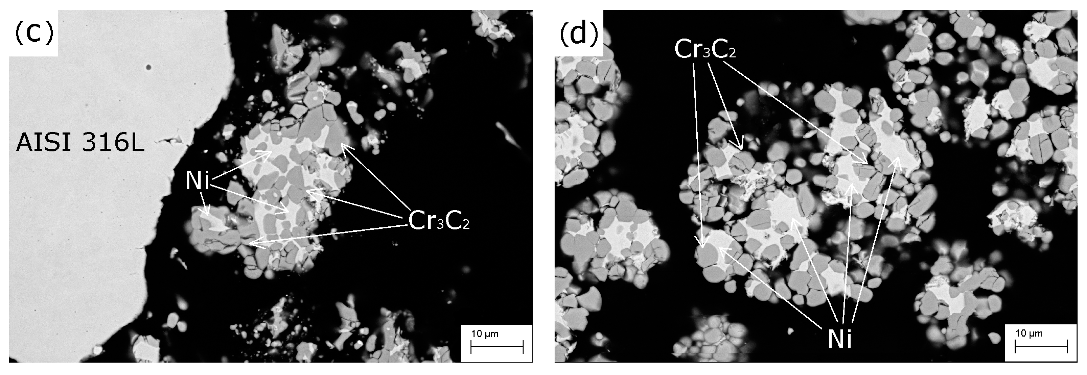
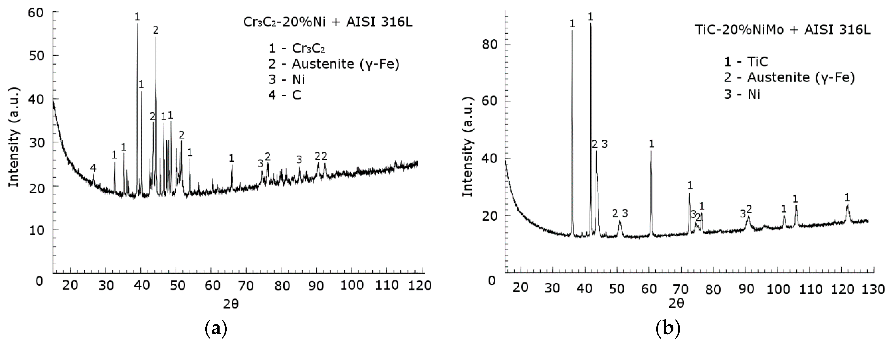
3.1. Characterization of Spray Powders

Due to the irregular shape of the particles, the flowability of both single MAS and elementary powders could not be measured. However, feedstock powder mixtures that contained spherical stainless steel (AISI 316L) particles exhibited a satisfactory flowability (Table 5).
Figure 1 shows the particle structures of the experimental powder mixtures and reference powder before thermoreaction. Experimental powders manufactured by the MAS method possessed particles of angular shape. In the particles of MAS (TiC–20%NiMo), the amount of cracks was higher than in the MAS (Cr3C2–20%Ni), which is a sign of a higher intrinsic brittleness of the TiC–NiMo cermets, as reported earlier in [31]. The average TiC grain size was also larger due to the higher sintering temperature: 1400 °C for TiC–20%NiMo [25] and 1075 °C for Cr3C2–20%Ni [23]. Particles of pure titanium (Figure 1b) exhibited an angular-like profile similar to TiC–20%NiMo particles, which, without adding mediators such as stainless steel, decreased its flowability remarkably. Particles of commercial Cr3C2–25%NiCr composition were found to be nearly round shaped with the presence of some porosity (Figure 1d).
Results of the XRD analysis of the experimental MAS powders are shown in Figure 2. Two main phases were revealed in each composition: chromium carbide (Cr3C2) and austenite (γ-Fe) in the Cr-based cermet powder and titanium carbide (TiC) and austenite (γ-Fe) in the Ti-based cermet powder. Additionally, metallic Ni was found in both compositions together with an insignificant amount of C in the Cr-based composition. The analysis of the XRD result of the agglomerated mixture of Ti, C and stainless steel is not presented. Unlike the MAS powders, it was not exposed to any kind of treatment at all; therefore, no phase transformation of its constituents is expected.

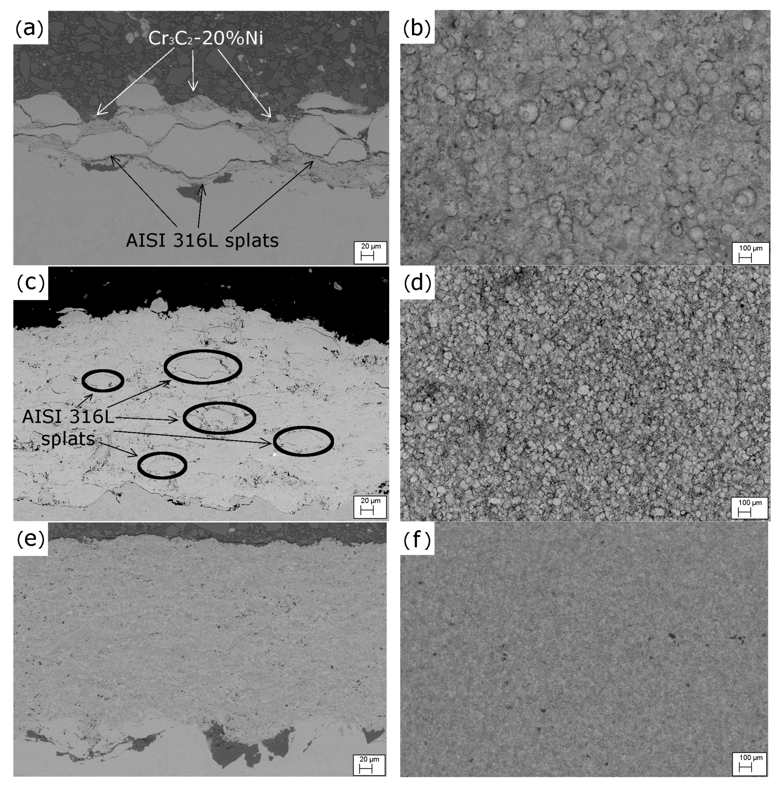
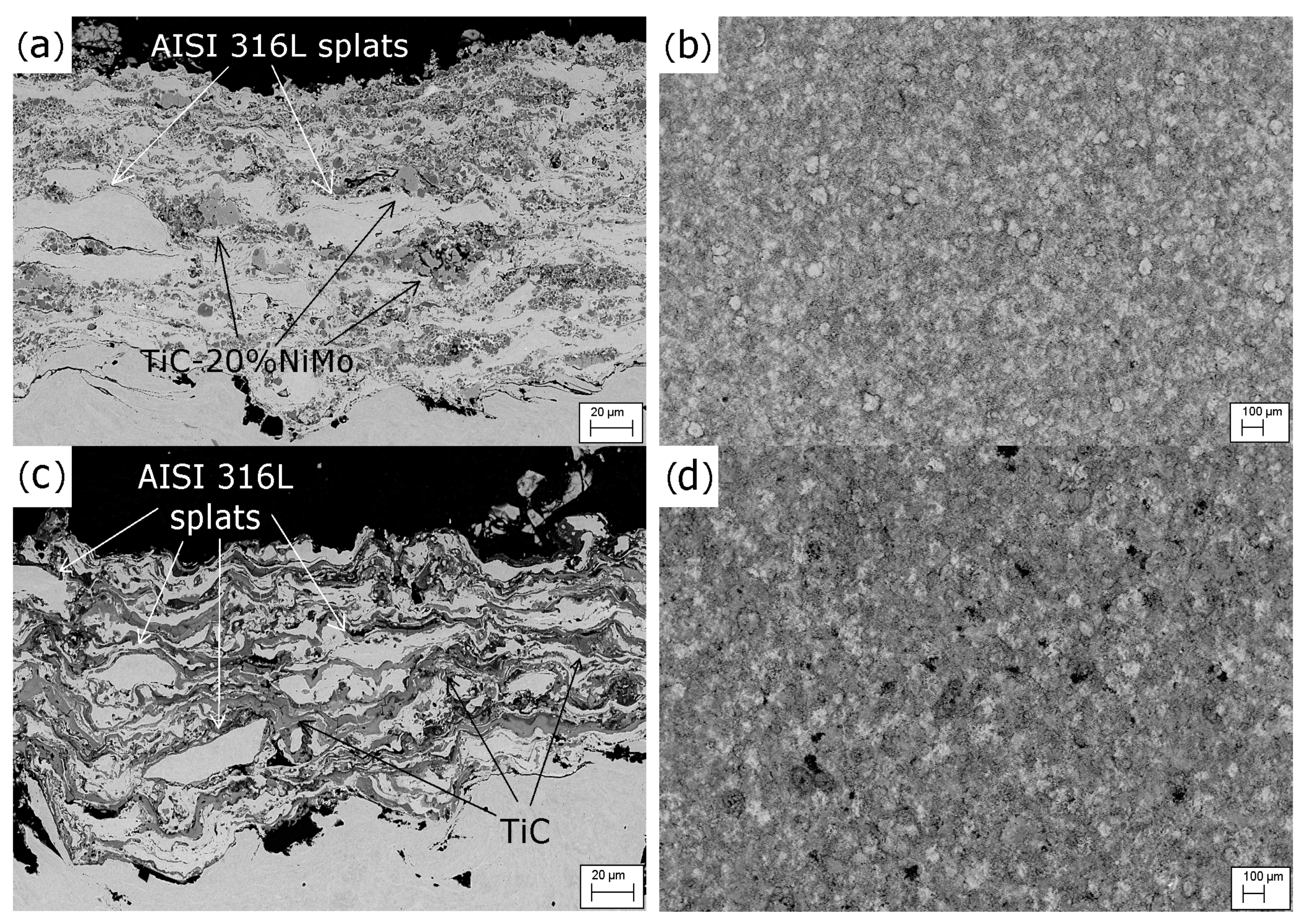
3.2. Deposition of Coatings

In the deposition process of experimental Cr-based composition, stainless steel particles demonstrated a low melting ability, which, in turn, decreased its matrix-forming potential. This resulted in inhomogeneous structure of the coating, as well as low cohesion between the splats and the relatively small thickness of the coating (Figure 3a,b). Particles of pure stainless steel melted better; however, separate splats could still be clearly distinguished (Figure 3c). In Figure 3d, the SEM image of a surface depicts an abundance of unmelted stainless steel particles. This might be caused by the average size of the stainless steel particles (20–90 μm), which, as compared to cermets, may require more heat for complete melting. As expected, Cr3C2–25%NiCr coating obtained from commercial powder had a good homogeneity and dense carbide structure (Figure 3e,f). Due to its good flowability and, therefore, the absence of stainless steel in this powder, all carbide particles were properly melted.
Coatings produced from the Ti-based MAS powder and the RTS mixture of Ti, C and stainless steel (Figure 4) exhibited much better homogeneity and fewer unmolten particles than those of the Cr-based MAS powder. This effect can be the result of the difference in spraying parameters (Table 3). Some porosity was observed on the surface of the coatings (Figure 4b,d). The Ti-based MAS coating possessed a lamellar structure while the RTS coating consisted of swirled alternating layers of the iron-based matrix and TiC reinforcement with minor cracks. Nevertheless, the complete melting of stainless steel particles was not achieved in either of the coatings. The distribution of constituents in the TiC reinforcement of the Ti-based coatings is shown in Figure 5.
Phase compositions of the experiment coatings, as evaluated by XRD, are presented in Table 6. The analysis has revealed the presence of two main phases in each coating. They were either TiC or Cr3C2 and austenite (γ-Fe). The Cr3C2 phase did not change to Cr7C3 after spraying, however, a small amount (~4.4 wt.%) of Cr2O3 was found in the Cr-based MAS coating. The α-Ti phase could be formed due to the excessive burning out of carbon, meant for bonding with Ti. XRD diffractograms of the experimental coatings are shown in Figure 6.

3.3. Hardness of the Coatings

MAS (Cr3C2–20%Ni) + AISI 316L coating demonstrated the highest surface hardness among the experimental coatings, while the cross-sectional hardness among developed coatings was highest in the MAS (TiC–20%NiMo) + AISI 316L coating (Table 7).

3.4. Abrasive Wear

Figure 7 presents the data of the abrasive rubber wheel wear (ARWW) test according to ASTM G65 standard. Experimental MAS (TiC–20%NiMo) + AISI 316L coating exhibited a slightly lower wear rate than the commercial Cr3C2–25%NiCr coating. Both experimental Ti-based coatings showed better results than Hardox 400 steel, whose wear rate data were taken from [32].
As can be seen from Figure 7 below, the presence of a carbide phase in the coatings with iron matrix increases their wear resistance, except for the coating with the MAS (Cr3C2–20%Ni) reinforcement. The relatively low cohesion between the latter and the stainless steel matrix is the most probable reason for the relatively low wear resistance of the corresponding coating.
Somewhat surprising are the nearly equal wear rates of the MAS (TiC–20%NiMo) + AISI 316L and the reference Cr3C2–25%NiCr coating. To further explore this phenomenon, wear mechanisms of the coatings under abrasive sliding wear (ARWW) (Figure 8) and abrasive–erosive wear (AEW) with low impact angle (α = 30°) (Figure 9) were evaluated. The common wear mechanism for the performed tests (ARWW and AEW) was microcutting. In the case of plastic materials (AISI 316L, Hardox 400), numerous grooves with metallic chips were found on the surface. Additionally, these reference materials were subjected to forming surface pits via material depletion, but were crack-free without visible material fracturing (Figure 10e,f).
For the Cr-based coatings (MAS (Cr3C2–20%Ni) + AISI 316L; Cr3C2–25%NiCr (Amperit)), the wear mechanism was a combination of the microcutting of the softer metallic matrix and the microchipping of brittle carbide reinforcement. The abrasive, seemingly, had been depleting the surrounding metallic matrix and the consequent peeling of carbide particles occured (Figure 8c,d and Figure 9c,d). These coatings were observed to have additional microcracking and spalling. In the composite Ti-based coatings (MAS and RTS), the wear was similar to that of the Cr-based MAS coating. The wear of the steel matrix was more intense compared to the carbide reinforcement (Figure 8a,b). In some parts, carbide clusters were depleted, delaminated (Figure 8b) or formed surface pits (Figure 9a,b).
Silica abrasive residues were observed on the surface of experimental coating RTS (Ti + C) + AISI 316L (Figure 8b). These defects may have emerged due to the domination in the composition of iron solid solutions, which gives the coating ductile properties.
Resistance of the developed materials to abrasive–erosive wear is shown in Figure 10. During the run-in test with 2 kg of silica, Hardox 400 steel showed almost two times less material loss than during a regular test with 6 kg of abrasive. This means that silica particles embedded in the surface of the tested samples due to intrinsically softer structure of metals [33]. On the SEM images, silica residues were observed on the tested surfaces even after regular testing (Figure 10f). Therefore, the plasticity of Hardox 400 steel and AISI 316L sprayed coating allowed them to exhibit the lowest loss of material. As for carbide-containing coatings, generally they possess higher brittleness under impact erosion than their metallic counterparts. In this study, each experimental coating contained roughly 40 wt.% of carbide phase, except for the RTS coating (Table 6). As a result, the coatings did not demonstrate competitive wear resistance in the abrasive–erosive testing. However, due to the presence of steel matrix, both Ti-based coatings outperformed the commercial Cr3C2–25%NiCr (Amperit) coating by 44% (MAS) and 11% (RTS). MAS (Cr3C2–20%Ni) + AISI 316L coating exhibited the lowest wear resistance due to its weak intersplat cohesion and low coating thickness.

4. Conclusions

  • HVOF sprayed wear-resistant composite coatings were designed from cermet powders produced by mechanically activated synthesis (MAS) and from the agglomerated mixture of elemental powders.
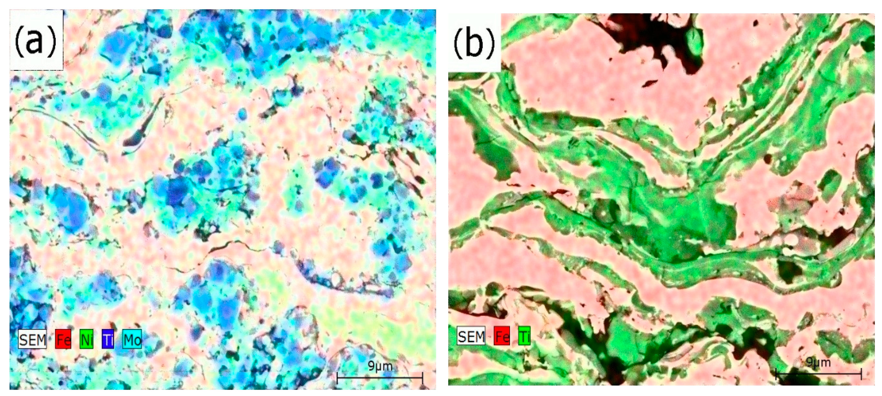
  • Carbide phase formation was achieved by the carbothermal reduction of TiO2 via MAS and by in situ synthesis during the deposition of the agglomerated mixture via reactive thermal spray (RTS) of (Ti + C) + AISI 316L. The Ti-based MAS coating showed homogeneous and fine-grained microstructure.
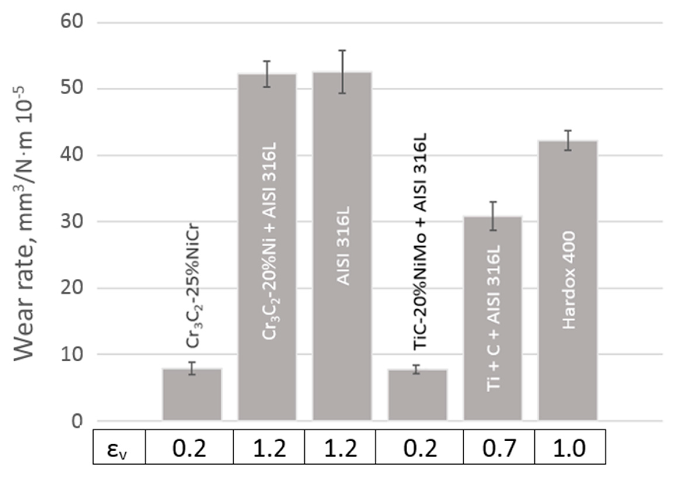
  • Developed Ti-based coatings (MAS and RTS) were demonstrated to be superior to Cr3C2–25%NiCr coating performance in the abrasive–erosive test. However, the abrasive–erosive wear resistance of the developed materials can be enhanced even further by increasing the presence of metal matrix in the composite. Compared to the Ti-based RTS coating, the Ti-based MAS coating is more applicable to abrasive rubber wheel wear due to containing 10% more of the hard carbide phase. Its performance was slightly better than that of the reference Cr3C2–25%NiCr coating. Cr-based MAS coating did not exhibit satisfactory wear resistance due to its inhomogeneous microstructure.

Author Contributions

D.T., A.S. and P.K. conceived and designed the experiments; D.T. and D.G. performed powder preparation; K.J. supervised compliance with methodology; M.V. and J.A. performed HVOF spraying; T.T. conducted SEM imaging; F.L. carried out the XRD experiments and their analysis; M.A. directed the wear tests; D.T. analyzed the data and wrote the paper; A.S. and R.M. contributed to the discussion and interpretation of the results; P.K. supervised and directed the research. All authors have read and agreed to the published version of the manuscript.

Funding

This research was funded by the Estonian Research Council in the frames of the projects IUT19-29 and PRG665. It was also supported by the Dora Plus academic mobility program as part of the EU Regional Development Fund.

Acknowledgments

Dmytro Tkachivskyi gratefully acknowledges the Research and Testing Institute Plzen (Pilsen, Czech Republic) for the conducting spraying experiments and the Institute of Plasma Physics (Prague, Czech Republic) for the help with the characterization of powders and coatings.

Conflicts of Interest

The authors declare no conflict of interest.

References

  1. Davis, E.J. Introduction to Applications for Thermal Spray Processing. In Handbook of Thermal Spray Technology; Davis, J.R., Ed.; ASM International: Geauga County, OH, USA, 2004; p. 172. [Google Scholar]
  2. Sarjas, H.; Kulu, P.; Juhani, K.; Vuoristo, P. Vuoristo, Novel WC-Co Spray Powders and HVOF Sprayed Coatings on Their Basis. In Proceedings of the 28th International Conference on Surface Modification Technologies, Tampere, Finland, 16–18 June 2014. [Google Scholar]
  3. Sarjas, H.; Kulu, P.; Juhani, K.; Viljus, M.; Matikainen, V.; Vuoristo, P. Wear resistance of HVOF sprayed coatings from mechanically activated thermally synthesized Cr3C2–Ni spray powder. Proc. Est. Acad. Sci. 2016, 65, 101. [Google Scholar] [CrossRef]
  4. Bordbar, H.; Yousefi, A.A.; Abedini, H. Production of titanium tetrachloride (TiCl4) from titanium ores: A review. Polyolefins J. 2017, 4, 150–169. [Google Scholar]
  5. Kang, J.; Okabe, T.H. Removal of Iron from Titanium Ore through Selective Chlorination Using Magnesium Chloride. Mater. Trans. 2013, 54, 1444–1453. [Google Scholar] [CrossRef] [Green Version]
  6. Woo, Y.-C.; Kang, H.-J.; Kim, D.J. Formation of TiC particle during carbothermal reduction of TiO2. J. Eur. Ceram. Soc. 2007, 27, 719–722. [Google Scholar] [CrossRef]
  7. Rahimi-Vahedi, A.; Adeli, M.; Saghafian, H. Formation of Fe-TiC composite clad layers on steel using the combustion synthesis process. Surf. Coat. Technol. 2018, 347, 217–224. [Google Scholar] [CrossRef]
  8. Terry, B.S.; Chinyamakobvu, O.S. In situ production of Fe-Tic composites by reactions in liquid iron alloys. J. Mater. Sci. Lett. 1991, 10, 628–629. [Google Scholar] [CrossRef]
  9. Nuilek, K.; Memongkol, N.; Niyomwas, S. The Effect of TiO2 on Synthesizing Fe-TiC Composites. In Proceedings of the 4th Thailand Materials Science and Technology Conference, Bangkok, Thailand, 31 March–1 April 2006. [Google Scholar]
  10. Sarjas, H.; Surzhenkov, A.; Juhani, K.; Antonov, M.; Adoberg, E.; Kulu, P.; Viljus, M.; Traksmaa, R.; Matikainen, V.; Vuoristo, P. Abrasive-Erosive Wear of Thermally Sprayed Coatings from Experimental and Commercial Cr3C2-Based Powders. J. Therm. Spray Technol. 2017, 26, 2020–2029. [Google Scholar] [CrossRef]
  11. Zhang, G.; Zheng, Y.; Zhou, W.; Zhao, Y.; Zhang, J.; Ke, Z.; Yu, L. Microstructure and mechanical properties of Ti(C,N)-based cermets fabricated by in situ carbothermal reduction of TiO2 and subsequent liquid phase sintering. Ceram. Int. 2018, 44, 3092–3098. [Google Scholar] [CrossRef]
  12. Yu, H.; Zhang, W.; Wang, H.; Ji, X.; Song, Z.; Li, X.; Xu, B. In-situ synthesis of TiC/Ti composite coating by high frequency induction cladding. J. Alloy Compd. 2017, 701, 244–255. [Google Scholar] [CrossRef] [Green Version]
  13. Khalili, A.; Goodarzi, M.; Mojtahedi, M.; Torkamany, M.J. Solidification microstructure of in-situ laser-synthesized Fe-TiC hard coating. Surf. Coat. Technol. 2016, 307, 747–752. [Google Scholar] [CrossRef]
  14. Wang, X.; Song, S.; Qu, S.; Zou, Z. Characterization of in situ synthesized TiC particle reinforced Fe-based composite coatings produced by multi-pass overlapping GTAW melting process. Surf. Coat. Technol. 2007, 201, 5899–5905. [Google Scholar] [CrossRef]
  15. Emamian, A.; Corbin, S.F.; Khajepour, A. Tribology characteristics of in-situ laser deposition of Fe-TiC. Surf. Coat. Technol. 2012, 206, 4495–4501. [Google Scholar] [CrossRef]
  16. Gallo, S.C.; Alam, N.; O’Donnell, R. In Situ Synthesis of TiC-Fe Composite Overlays from Low Cost TiO2 Precursors Using Plasma Transferred Arc Deposition. J. Therm. Spray Technol. 2013, 23, 551–556. [Google Scholar] [CrossRef]
  17. Liu, H.; Huang, J. Reactive thermal spraying of TiC-Fe composite coating by using asphalt as a carbonaceous precursor. J. Mater. Sci. 2005, 40, 4149–4151. [Google Scholar] [CrossRef]
  18. Sun, X.; Huang, J.; Yang, J.; Chen, S. Microstructure evolution and mechanical properties of in-situ bimodal TiC-Fe coatings prepared by reactive plasma spraying. Ceram. Int. 2019, 45, 5848–5857. [Google Scholar] [CrossRef]
  19. Almangour, B.; Grzesiak, D.; Yang, J.-M. In-situ formation of novel TiC-particle-reinforced 316L stainless steel bulk-form composites by selective laser melting. J. Alloy. Compd. 2017, 706, 409–418. [Google Scholar] [CrossRef]
  20. Bolelli, G.; Colella, A.; Lusvarghi, L.; Morelli, S.; Puddu, P.; Righetti, E.; Sassatelli, P.; Testa, V. TiC-NiCr thermal spray coatings as an alternative to WC-CoCr and Cr3C2-NiCr. Wear 2020, 203273. [Google Scholar] [CrossRef]
  21. Surzhenkov, A.; Goljandin, D.; Traksmaa, R.; Viljus, M.; Talviste, K.; Aruniit, A.; Latokartano, J.; Kulu, P. High Temperature Erosion Wear of Cermet Particles Reinforced Self-Fluxing Alloy HVOF Sprayed Coatings. Mater. Sci. (Medžiagotyra) 2015, 21, 386–390. [Google Scholar] [CrossRef] [Green Version]
  22. Pirso, J.; Viljus, M.; Letunovits, S.; Juhani, K. Reactive carburizing sintering—A novel production method for high quality chromium carbide–nickel cermets. Int. J. Refract. Met. Hard Mater. 2006, 24, 263–270. [Google Scholar] [CrossRef]
  23. Tkachivskyi, D.; Juhani, K.; Surzhenkov, A.; Kulu, P.; Viljus, M.; Traksmaa, R.; Jankauskas, V.; Leišys, R. Production of Thermal Spray Cr3C2-Ni Powders by Mechanically Activated Synthesis. Key Eng. Mater. 2019, 799, 31–36. [Google Scholar] [CrossRef]
  24. Pirso, J.; Viljus, M.; Juhani, K.; Kuningas, M. Three-body abrasive wear of TiC-NiMo cermets. Tribol. Int. 2010, 43, 340–346. [Google Scholar] [CrossRef]
  25. Jõeleht, M.; Pirso, J.; Juhani, K.; Viljus, M.; Traksmaa, R. The formation of reactive sintered (Ti, Mo)C-Ni cermet from nanocrystalline powders. Int. J. Refract. Met. Hard Mater. 2014, 43, 284–290. [Google Scholar] [CrossRef]
  26. Kulu, P.; Pihl, T. Selection Criteria for Wear Resistant Powder Coatings Under Extreme Erosive Wear Conditions. J. Therm. Spray Technol. 2002, 11, 517–522. [Google Scholar] [CrossRef]
  27. ASTM International. ASTM B213-20, Standard Test Methods for Flow Rate of Metal Powders Using the Hall Flowmeter Funnel; ASTM International: West Conshohocken, PA, USA, 2020. [Google Scholar]
  28. ISO 6507-1. Metallic Materials—Vickers Hardness Test 2018; International Organization for Standardization: Geneva, Switzerland, 2018. [Google Scholar]
  29. ASTM International. ASTM G65-16e1, Standard Test Method for Measuring Abrasion Using the Dry Sand/Rubber Wheel Apparatus; ASTM International: West Conshohocken, PA, USA, 2016. [Google Scholar]
  30. GOST 23.201-78 Standard. Products Wear Resistance Assurance, Gas Abrasive Wear Testing of Materials and Coatings with Centrifugal Accelerato; Publishing House of Standards: Moscow, Russia, 1987. (In Russian) [Google Scholar]
  31. Pirso, J.; Viljus, M.; Letunovitš, S.; Juhani, K.; Joost, R. Three-body abrasive wear of cermets. Wear 2011, 271, 2868–2878. [Google Scholar] [CrossRef]
  32. Antonov, M.; Veinthal, R.; Yung, D.-L.; Katušin, D.; Hussainova, I. Mapping of impact-abrasive wear performance of WC-Co cemented carbides. Wear 2015, 332, 971–978. [Google Scholar] [CrossRef]
  33. Antonov, M.; Pirso, J.; Vallikivi, A.; Goljandin, D.; Hussainova, I. The effect of fine erodent retained on the surface during erosion of metals, ceramics, plastic, rubber and hardmetal. Wear 2016, 354–355, 53–68. [Google Scholar] [CrossRef]
Figure 1. Particle structure of: (a) MAS (TiC–20%NiMo) + AISI 316L; (b) Ti + C + AISI 316L; (c) MAS (Cr3C2–20%Ni) + AISI 316L; and (d) Cr3C2–25%NiCr (Amperit).
Coatings 10 01092 g001aCoatings 10 01092 g001b
Figure 2. XRD patterns of experimental MAS powders: (a) Cr-based powder; (b) Ti-based powder.
Coatings 10 01092 g002
Figure 3. Microstructure (left column) and surface images (right column) of high velocity oxy fuel (HVOF) sprayed coatings: (a,b) MAS (Cr3C2–20%Ni) + AISI 316L; (c,d) AISI 316L (commercial); (e,f) Cr3C2–25%NiCr (Amperit).
Coatings 10 01092 g003
Figure 4. Microstructure (left column) and surface images (right column) of Ti-based HVOF sprayed coatings: (a,b) MAS (TiC–20%NiMo) + AISI 316L; (c,d) RTS (Ti + C) + AISI 316L.
Coatings 10 01092 g004
Figure 5. EDS maps of Ti-based coatings: (a) MAS (TiC–20%NiMo) + AISI 316L; (b) RTS (Ti + C) + AISI 316L.
Coatings 10 01092 g005
Figure 6. XRD patterns of the HVOF sprayed coatings. (a) Ti-based MAS coating; (b) Ti-based RTS coating; (c) Cr-based MAS coating; (d) Reference coating (Amperit).
Coatings 10 01092 g006
Figure 7. Wear rates and relative volumetric wear resistance (εν) of HVOF sprayed coatings to Hardox 400 steel at ARWW.
Coatings 10 01092 g007
Figure 8. Topography of the wear surfaces after ARWW: (a) MAS (TiC–20%NiMo) + AISI 316L; (b) RTS (Ti + C) + AISI 316L; (c) MAS (Cr3C2–20%Ni) + AISI 316L; (d) Cr3C2–25%NiCr (Amperit); (e) AISI 316L.
Coatings 10 01092 g008
Figure 9. The topography of the wear surfaces after AEW: (a) MAS (TiC–20%NiMo) + AISI 316L; (b) RTS (Ti + C) + AISI 316L; (c) MAS (Cr3C2–20%Ni) + AISI 316L; (d) Cr3C2–25%NiCr (Amperit); (e) AISI 316L; (f) Hardox 400.
Coatings 10 01092 g009
Figure 10. Wear rates and relative volumetric wear resistance (εν) to the Hardox 400 steel of HVOF sprayed coatings at AEW.
Coatings 10 01092 g010
Table 1. Chemical composition and the amounts of constituents in the spraying powders.
CompositionConstituents and Their Amount, (wt.%)GradeManufacturerAverage Particle Size (Range), (μm)Chemical Composition, (wt.%)
MAS (TiC–20%NiMo)64 TiO2Pretiox CG 100Precheza a.s.0.02100 TiO2
16 C7782-42-5Imerys SA (Timrex KS6)6.4599.8 C,
0.1 moisture,
0.06 ash, bal. residuals
13.3 NiNi-7262Pacific Particulate Materials Ltd.2.499.7 Ni, 0.14 O, 0.14 C, bal. residuals
6.7 MoMo-7164Pacific Particulate Materials Ltd.2.3299.8 Mo, 0.05 O, 0.0003 Fe, bal. residuals
MAS (Cr3C2–20%Ni)69.3 CrCr-6995Pacific Particulate Materials Ltd.6.6599.5 Cr, 0.38 O, 0.01 Fe, bal. residuals
10.7 C7782-42-5Imerys SA (Timrex KS6)6.4599.8 C,
0.1 moisture,
0.06 ash, bal. residuals
20 NiNi-7262Pacific Particulate Materials Ltd.2.499.7 Ni, 0.14 O, 0.14 C, bal. residuals
Cr3C2–25%NiCr-Amperit 588.074H.C. Starck15–45Base Cr, 18–22 Ni, 0.6 O, 9–11 C, 0.5 Fe
RTS (Ti + C) +
AISI 316L
32.8 TiHFTi-1 99.5%Baoji Ziyu Metal Materials CO., Ltd.20–9098.8 Ti, 1.2 Al
8.2 C 1--20–90100 C
59 AISI 316L16316Castolin Eutectic®20–90Base Fe, 0.03 C, 17.5 Cr, 13 Ni, 2.7 Mo
1 Obtained by disintegrator milling of graphite in Tallinn University of Technology.
Table 2. Reinforcement to matrix ratio of the experimental powders.
CompositionMAS (Cr3C2–20%Ni):AISI 316LMAS (TiC–20%NiMo):AISI 316LTi:C:
AISI 316L
Ratio, (vol.%)50:5056:4432.8:8.2:59
Table 3. Spraying parameters.
CompositionOxygen Flow Rate, (L/min)Kerosene Flow Rate, (L/h)Powder Feed Rate, (g/min)Carrier Gas Flow Rate, (L/min)Spraying Distance, (mm)Number of Passes
MAS (TiC–20%NiMo)
+ AISI 316L
8702860538014
RTS (Ti + C) + AISI 316L870286053806
MAS (Cr3C2–20%Ni)
+ AISI 316L
8722768538012
Cr3C2–25%NiCr (Amperit)8722768538012
AISI 316L9002410053607
Table 4. Parameters of the abrasive wear tests.
Wear
Test
Load, (N)Linear Speed, (m/s)Impact Angle, (°)Wheel Diameter, (mm)Number of Wheel RevolutionsTesting Temp., (°C)Abrasive Type and Size, (mm)Abrasive Amount, (kg)Abrasive Feed Rate, (g/s)Duration of the Test, (s)
ARWW1302.4227100720Silica, 0.2–0.31.855–6.5300
AEW40 13020Silica, 0.2–0.32 + 6 26.942400
1 Velocity of abrasive particles; 2 Run-in—2 kg, regular test—6 kg.
Table 5. Flowability of the experimental compositions and reference powders.
CompositionFlowability, s
MAS (TiC–20%NiMo) + AISI 316L31.9 ± 0.3
RTS (Ti + C) + AISI 316L49.2 ± 1.0
MAS (Cr3C2–20%Ni) + AISI 316L55.7 ± 2.2
Cr3C2–25%NiCr (Amperit)37.3 ± 0.2
AISI 316L15.2 ± 0.1
Table 6. Phase composition of the HVOF sprayed coatings.
Type of CoatingTiC, (wt.%)α-Ti, (wt.%)Cr3C2, (wt.%)Ni, (wt.%)γ-Fe, (wt.%)α-Fe, (wt.%)
MAS (TiC–20%NiMo) + AISI 316L37.853.29
RTS (Ti + C) + AISI 316L2712.847.612.6
MAS (Cr3C2–20%Ni) + AISI 316L36.144.814.6
Cr3C2–25%NiCr (Amperit)58.241.8
AISI 316L88.811.2
Table 7. Thickness and hardness of the HVOF sprayed coatings.
Type of CoatingThickness, (μm)Vickers Hardness HV, (GPa)
SurfaceCross-Section
HV1HV0.3HV0.3
MAS (TiC–20%NiMo) + AISI 316L1204.5 ± 1.0-4.5 ± 1.3
RTS (Ti + C) + AISI 316L904.0 ± 0.6-3.3 ± 0.7
MAS (Cr3C2–20%Ni) + AISI 316L55-4.9 ± 1.12.6 ± 0.8
Cr3C2–25%NiCr (Amperit)2638.8 ± 1.08.2 ± 2.19.2 ± 1.6
AISI 316L2033.2 ± 0.42.7 ± 1.23.1 ± 0.7
Publisher’s Note: MDPI stays neutral with regard to jurisdictional claims in published maps and institutional affiliations.

