Surface Modification and Enhancement of Ferromagnetism in BiFeO3 Nanofilms Deposited on HOPG

 , ,
, ,  ,
,  , and
, and 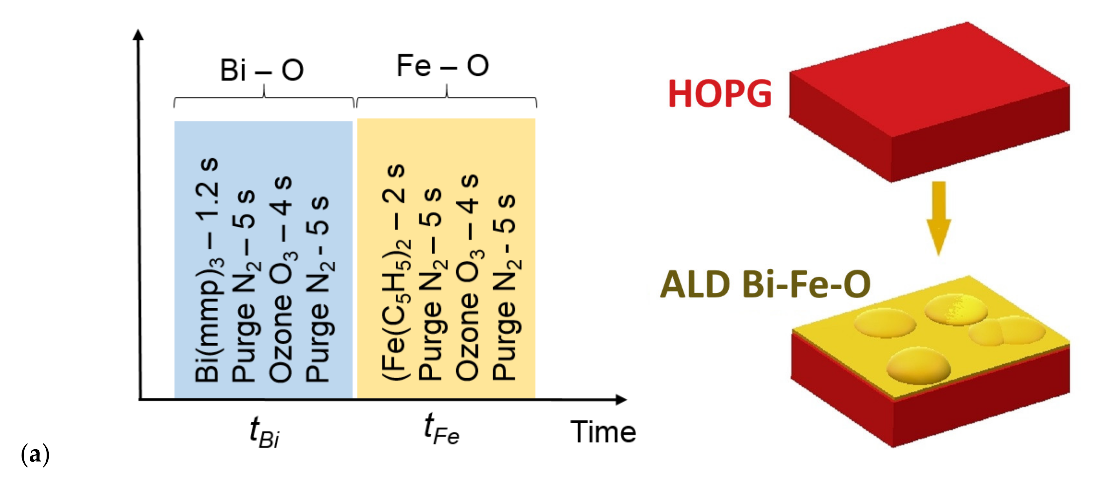
Abstract
:1. Introduction
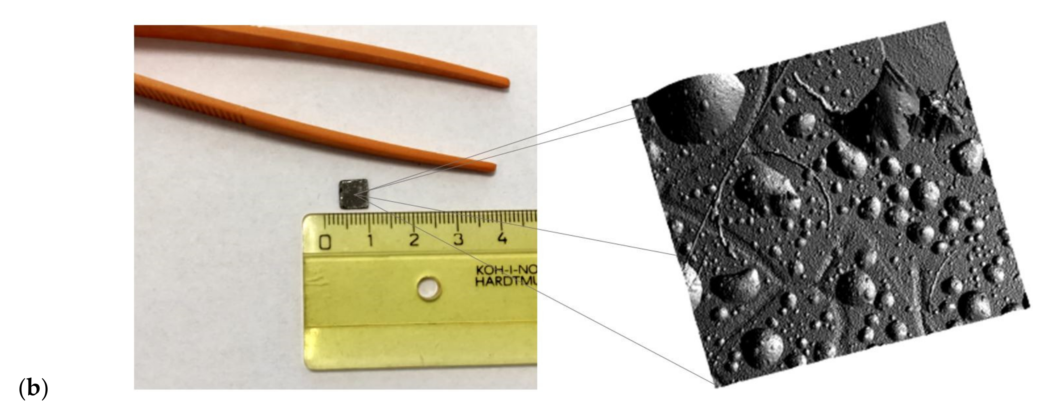
2. Experimental Details
3. Results and Discussion
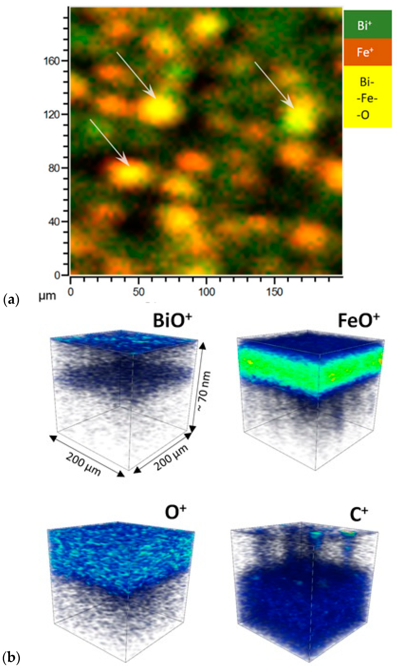
3.1. Secondary-Ion Mass Spectrometry (SIMS) analysis
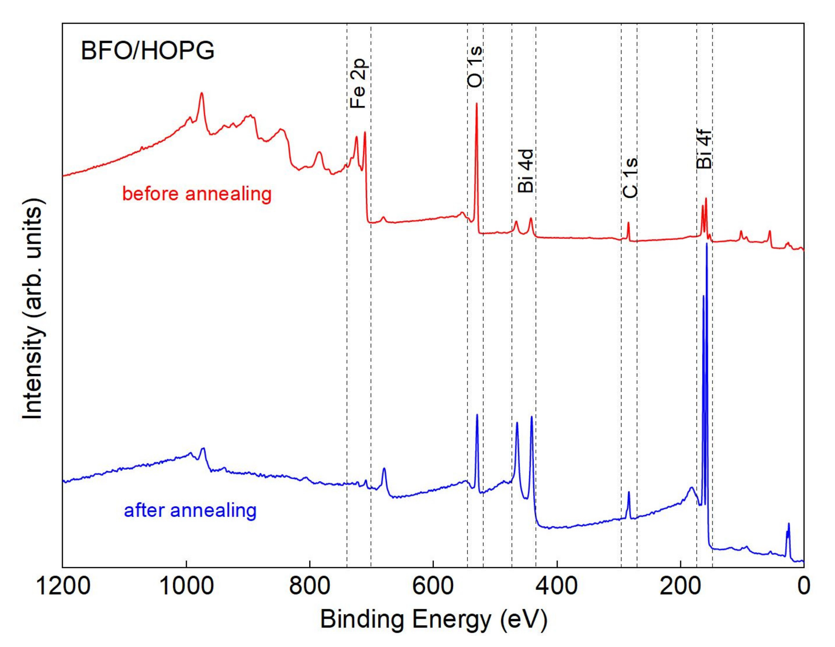
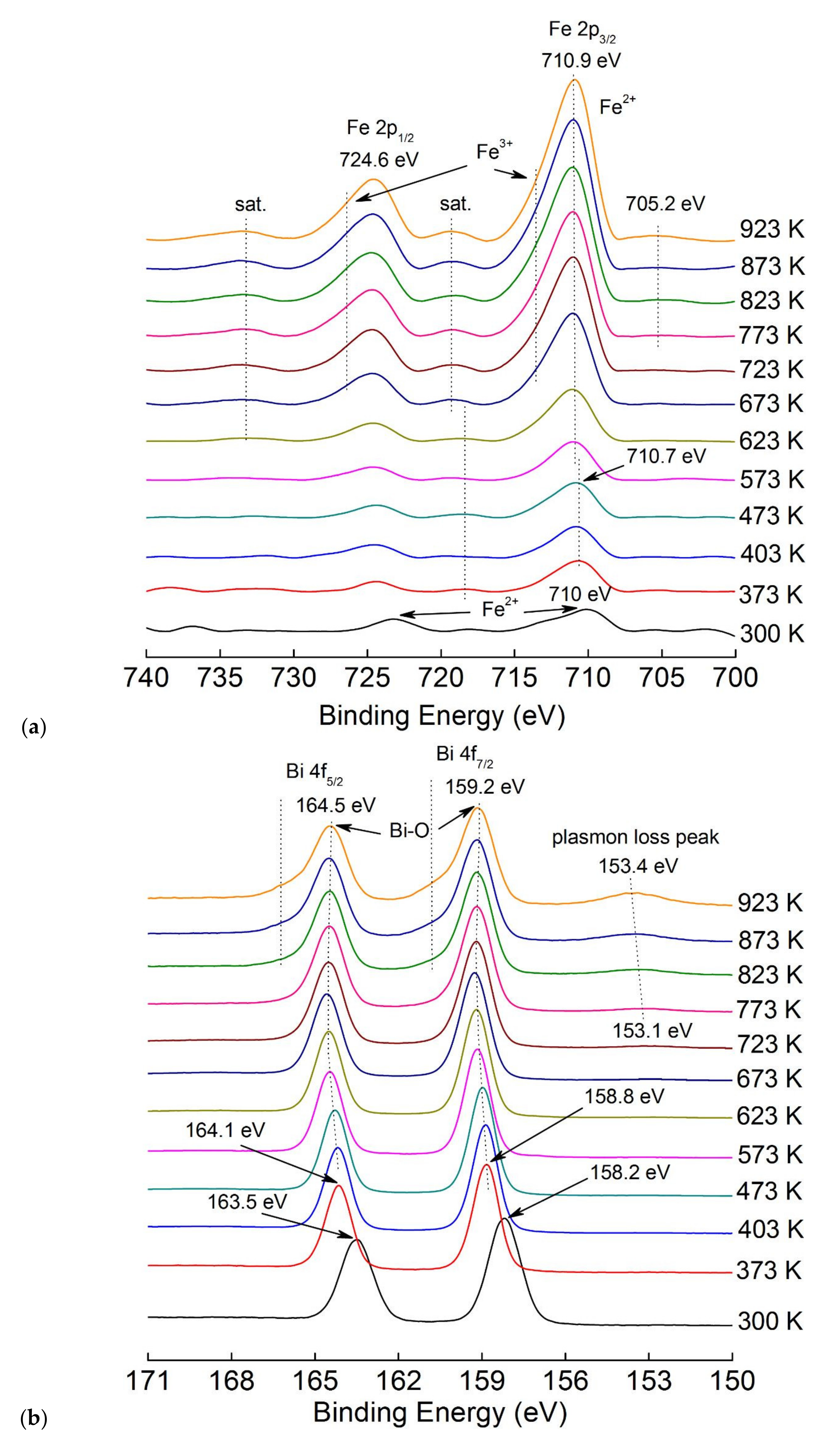
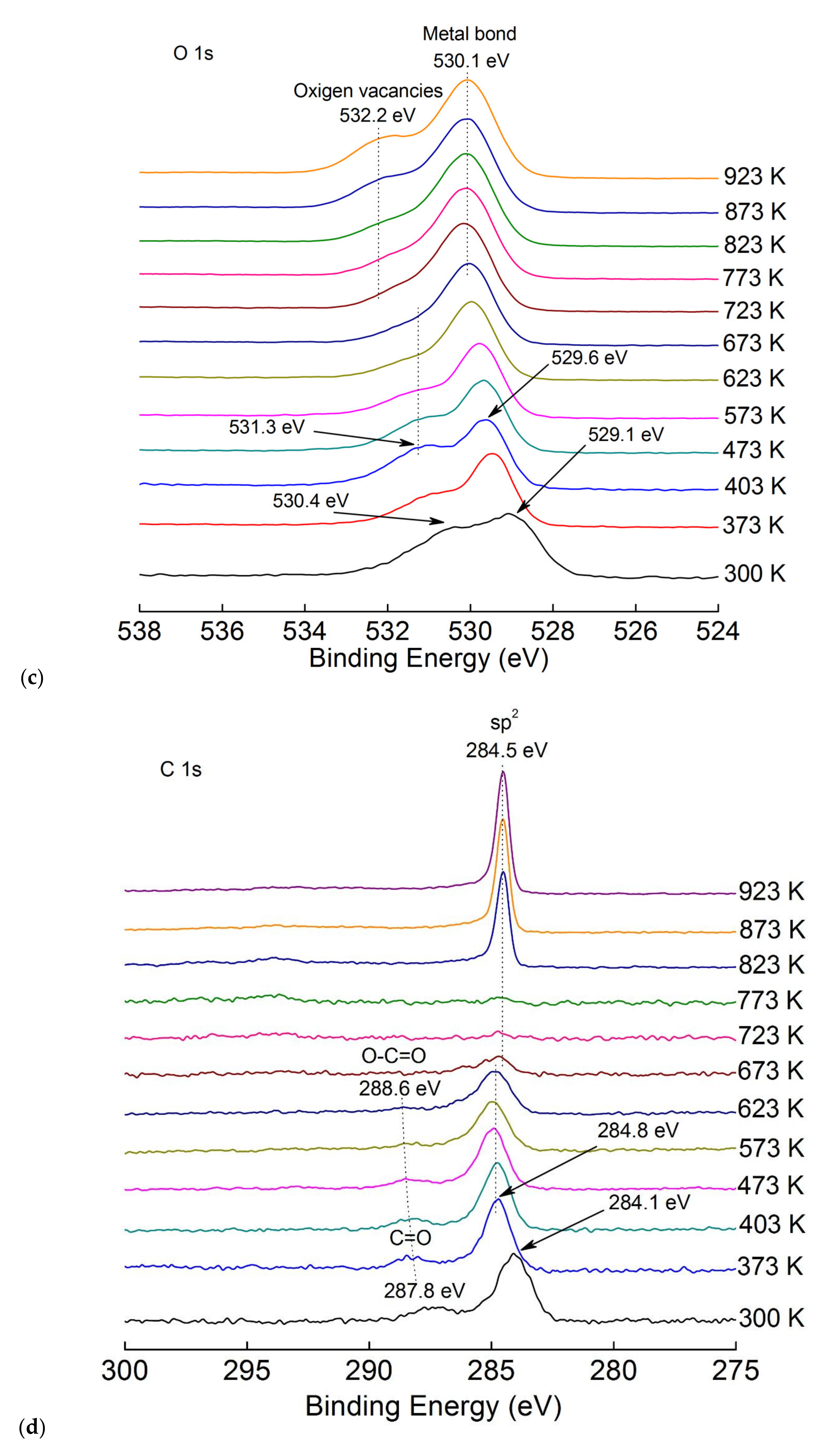
3.2. X-ray Photoelectron Spectroscopy (XPS) Analysis
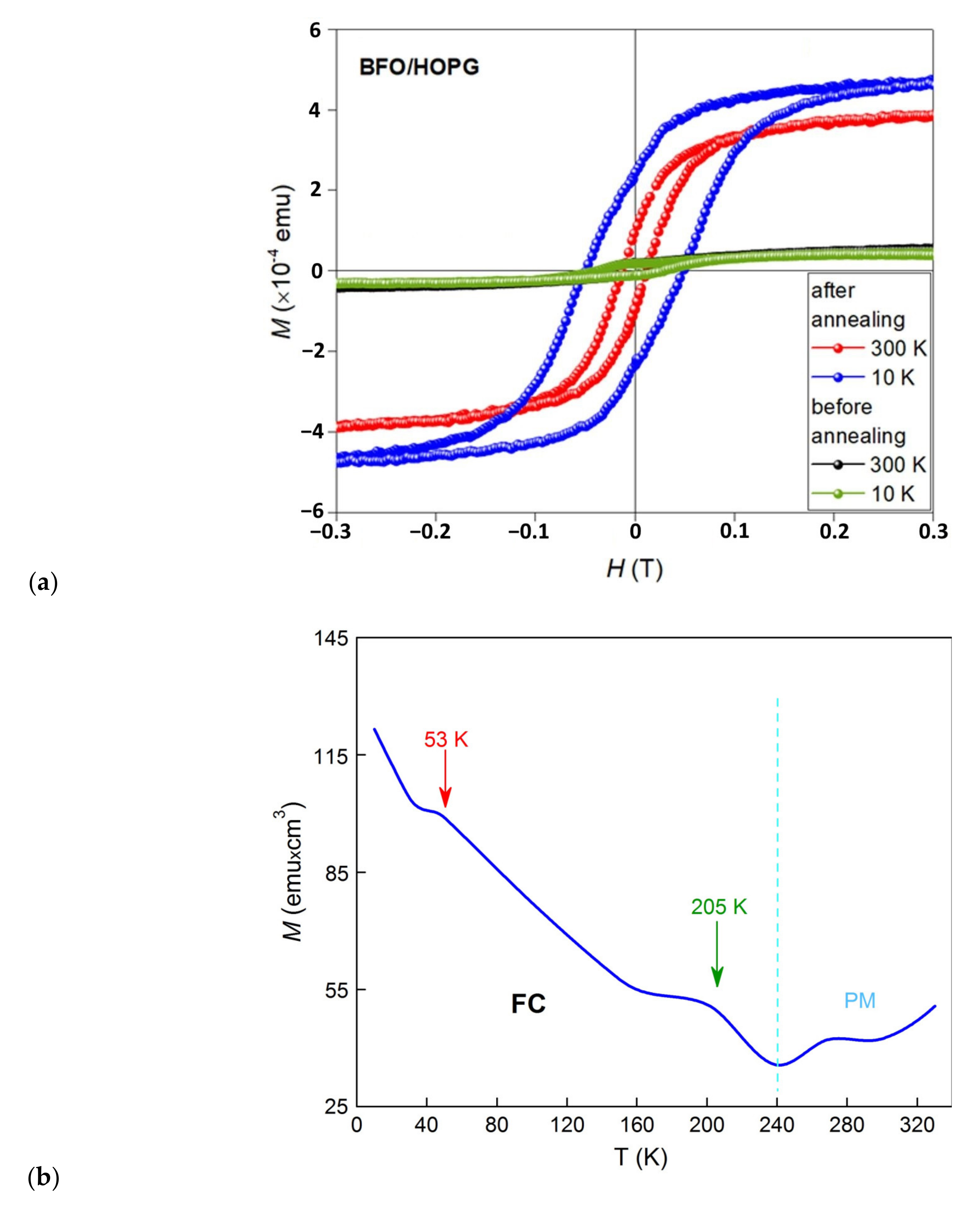
3.3. Vibrating Sample Measurement (VSM) Analysis
4. Conclusions
Supplementary Materials
Author Contributions
Funding
Conflicts of Interest
References
- Baek, S.-H.; Choi, S.; Kim, T.L.; Jang, H.W. Domain engineering in BiFeO3 thin films. Curr. Appl. Phys. 2017, 17, 688–703. [Google Scholar] [CrossRef]
- Guo, R.; You, L.; Zhou, Y.; Lim, Z.S.; Zou, X.; Chen, L.; Ramesh, R.; Wang, J. Non-volatile memory based on the ferroelectric photovoltaic effect. Nat. Commun. 2013, 4, 1990. [Google Scholar] [CrossRef] [Green Version]
- Vila-Fungueiriño, J.M.; Gomez, A.; Antoja-Lleonart, J.; Gazquez, J.; Magen, C.; Noheda, B.; Carretero-Genevrier, A. Direct and converse piezoelectric responses at the nanoscale from epitaxial BiFeO3 thin films grown by polymer assisted deposition. Nanoscale 2018, 10, 20155–20161. [Google Scholar] [CrossRef] [Green Version]
- Huang, C.; Chen, L. Effects of Interfaces on the Structure and Novel Physical Properties in Epitaxial Multiferroic BiFeO3 Ultrathin Films. Materials 2014, 7, 5403–5426. [Google Scholar] [CrossRef] [Green Version]
- Steffes, J.; Ristau, R.A.; Ramesh, R.; Huey, B.D. Thickness scaling of ferroelectricity in BiFeO3 by tomographic atomic force microscopy. Proc. Natl. Acad. Sci. USA 2019, 116, 2413–2418. [Google Scholar] [CrossRef] [Green Version]
- Graf, M.; Sepliarsky, M.; Machado, R.; Stachiotti, M. Dielectric and piezoelectric properties of BiFeO3 from molecular dynamics simulations. Solid State Commun. 2015, 218, 10–13. [Google Scholar] [CrossRef]
- Jeon, J.H.; Joo, H.-Y.; Kim, Y.M.; Lee, D.H.; Kim, J.-S.; Kim, Y.S.; Choi, T.; Park, B.H. Selector-free resistive switching memory cell based on BiFeO3 nano-island showing high resistance ratio and nonlinearity factor. Sci. Rep. 2016, 6, 23299. [Google Scholar] [CrossRef] [Green Version]
- Jiang, A.Q.; Zhang, Y. Next-generation ferroelectric domain-wall memories: Principle and architecture. NPG Asia Mater. 2019, 11, 2. [Google Scholar] [CrossRef] [Green Version]
- Shima, H.; Naganuma, H.; Okamur, S. Optical Properties of Multiferroic BiFeO3 Films. In Materials Science—Advanced Topics; IntechOpen: London, UK, 2013. [Google Scholar]
- Zhu, M.; Du, Z.; Liu, Q.; Chen, B.; Tsang, S.H.; Teo, E.H.T. Ferroelectric BiFeO3 thin-film optical modulators. Appl. Phys. Lett. 2016, 108, 233502. [Google Scholar] [CrossRef]
- Liou, Y.-D.; Chiu, Y.-Y.; Hart, R.T.; Kuo, C.-Y.; Huang, Y.-L.; Wu, Y.-C.; Chopdekar, R.V.; Liu, H.-J.; Tanaka, A.; Chen, C.-T.; et al. Deterministic optical control of room temperature multiferroicity in BiFeO3 thin films. Nat. Mater. 2019, 18, 580–587. [Google Scholar] [CrossRef] [Green Version]
- Pisarev, R.V.; Moskvin, A.S.; Kalashnikova, A.M.; Rasing, T. Charge transfer transitions in multiferroic BiFeO3 and related ferrite insulators. Phys. Rev. B 2009, 79, 79. [Google Scholar] [CrossRef] [Green Version]
- Si, Y.-H.; Xia, Y.; Shang, S.-K.; Xiong, X.-B.; Zeng, X.; Zhou, J.; Li, Y.-Y. Enhanced Visible Light Driven Photocatalytic Behavior of BiFeO₃/Reduced Graphene Oxide Composites. Nanomaterials 2018, 8, 526. [Google Scholar] [CrossRef] [Green Version]
- Pan, H.; Ma, J.; Ma, J.; Zhang, Q.; Liu, X.; Guan, B.; Gu, L.; Zhang, X.; Zhang, Y.-J.; Li, L.; et al. Giant energy density and high efficiency achieved in bismuth ferrite-based film capacitors via domain engineering. Nat. Commun. 2018, 9, 1813. [Google Scholar] [CrossRef] [Green Version]
- Qiao, Z.; Ren, W.; Chen, H.; Bellaiche, L.; Zhang, Z.; Macdonald, A.H.; Niu, Q. Quantum Anomalous Hall Effect in Graphene Proximity Coupled to an Antiferromagnetic Insulator. Phys. Rev. Lett. 2014, 112, 112. [Google Scholar] [CrossRef]
- Kumar, P.; Sharma, V.; Reboredo, F.A.; Yang, L.-M.; Pushpa, R. Tunable magnetism in metal adsorbed fluorinated nanoporous graphene. Sci. Rep. 2016, 6, 31841. [Google Scholar] [CrossRef] [Green Version]
- Huang, D.J.; Jeng, H.-T.; Chang, C.-F.; Guo, G.Y.; Chen, J.; Wu, W.P.; Chung, S.-C.; Shyu, S.G.; Wu, C.C.; Lin, H.-J.; et al. Orbital magnetic moments of oxygen and chromium inCrO2. Phys. Rev. B 2002, 66, 174440. [Google Scholar] [CrossRef] [Green Version]
- Yuan, H.; Chen, H.; Kuang, A.; Wu, B. Spin–orbit effect and magnetic anisotropy in Pt clusters. J. Magn. Magn. Mater. 2013, 331, 7–16. [Google Scholar] [CrossRef]
- Shin, H.W.; Son, J.Y. Multiferroic BiFeO3 thin films and nanodots grown on highly oriented pyrolytic graphite substrates. J. Cryst. Growth 2017, 480, 13–17. [Google Scholar] [CrossRef]
- Catalan, G.; Scott, J.F. Physics and Applications of Bismuth Ferrite. Adv. Mater. 2009, 21, 2463–2485. [Google Scholar] [CrossRef]
- Zhu, J.; Chen, M.; Qu, H.; Luo, Z.; Wu, S.; Colorado, H.A.; Wei, S.; Guo, Z. Magnetic field induced capacitance enhancement in graphene and magnetic graphene nanocomposites. Energy Environ. Sci. 2013, 6, 194–204. [Google Scholar] [CrossRef]
- Miao, Q.; Zeng, M.; Zhang, Z.; Lu, X.; Dai, J.; Gao, X.; Liu, J.-M. Self-assembled nanoscale capacitor cells based on ultrathin BiFeO3 films. Appl. Phys. Lett. 2014, 104, 182903. [Google Scholar] [CrossRef]
- Kartavtseva, M.; Gorbenko, O.; Kaul, A.; Murzina, T.; Savinov, S.; Barthélémy, A. BiFeO3 thin films prepared using metalorganic chemical vapor deposition. Thin Solid Films 2007, 515, 6416–6421. [Google Scholar] [CrossRef]
- Huang, Y.Q. Study on preparation and property of BiFeO3 thin films by PLD. Gongneng Cailiao/J. Funct. Mater. 2013, 44, 1469–1471. [Google Scholar] [CrossRef]
- Cha, J.; Ahn, J.; Lee, K.; JeongOk, C.; JeungSun, A.; KwangBae, L. Multiferroic BiFeO3 Thin Films Prepared by Using a Conventional RF Magnetron Sputtering Method. J. Korean Phys. Soc. 2009, 54, 844–848. [Google Scholar] [CrossRef]
- Akbashev, A.R.; Chen, G.; Spanier, J.E. A Facile Route for Producing Single-Crystalline Epitaxial Perovskite Oxide Thin Films. Nano Lett. 2013, 14, 44–49. [Google Scholar] [CrossRef]
- Marchand, B.; Jalkanen, P.; Tuboltsev, V.; Vehkamäki, M.; Puttaswamy, M.; Kemell, M.; Mizohata, K.; Hatanpää, T.; Savin, A.M.; Räisänen, J.; et al. Electric and Magnetic Properties of ALD-Grown BiFeO3 Films. J. Phys. Chem. C 2016, 120, 7313–7322. [Google Scholar] [CrossRef]
- Coll, M.; Gazquez, J.; Fina, I.; Khayat, Z.; Quindeau, A.; Alexe, M.; Varela, M.; Trolier-McKinstry, S.; Obradors, X.; Puig, T. Nanocrystalline Ferroelectric BiFeO3 Thin Films by Low-Temperature Atomic Layer Deposition. Chem. Mater. 2015, 27, 6322–6328. [Google Scholar] [CrossRef] [Green Version]
- Cavanagh, A.S.; Wilson, C.A.; Weimer, A.W.; George, S.M. Atomic layer deposition on gram quantities of multi-walled carbon nanotubes. Nanotechnol. 2009, 20, 255602. [Google Scholar] [CrossRef]
- Xuan, Y.; Wu, Y.Q.; Shen, T.; Qi, M.; Capano, M.A.; Cooper, J.A.; Ye, P.D. Atomic-layer-deposited nanostructures for graphene-based nanoelectronics. Appl. Phys. Lett. 2008, 92, 013101. [Google Scholar] [CrossRef] [Green Version]
- Young, M.J.; Musgrave, C.B.; George, S.M. Growth and Characterization of Al2O3 Atomic Layer Deposition Films on sp2-Graphitic Carbon Substrates Using NO2/Trimethylaluminum Pretreatment. ACS Appl. Mater. Interfaces 2015, 7, 12030–12037. [Google Scholar] [CrossRef]
- Wang, X.; Mao, W.; Wang, Q.; Zhu, Y.; Min, Y.; Zhang, J.; Yang, T.; Yang, J.; Li, X.; Huang, W. Low-temperature fabrication of Bi25FeO40 /rGO nanocomposites with efficient photocatalytic performance under visible light irradiation. RSC Adv. 2017, 7, 10064–10069. [Google Scholar] [CrossRef] [Green Version]
- Knápek, A.; Sobola, D.; Tománek, P.; Pokorná, Z.; Urbánek, M. Field emission from the surface of highly ordered pyrolytic graphite. Appl. Surf. Sci. 2017, 395, 157–161. [Google Scholar] [CrossRef]
- Papež, N.; Sobola, D.; Škvarenina, Ľ.; Skarvada, P.; Hemzal, D.; Tofel, P.; Grmela, L. Degradation analysis of GaAs solar cells at thermal stress. Appl. Surf. Sci. 2018, 461, 212–220. [Google Scholar] [CrossRef]
- Jalil, M.A.; Chowdhury, S.S.; Alam Sakib, M.; Yousuf, S.M.E.H.; Ashik, E.K.; Firoz, S.H.; Basith, M.A. Temperature-dependent phase transition and comparative investigation on enhanced magnetic and optical properties between sillenite and perovskite bismuth ferrite-rGO nanocomposites. J. Appl. Phys. 2017, 122, 084902. [Google Scholar] [CrossRef]
- Zhang, Y.; Wang, Y.; Qi, J.; Tian, Y.; Sun, M.; Zhang, J.; Hu, T.; Wei, M.; Liu, Y.; Yang, J. Enhanced Magnetic Properties of BiFeO3 Thin Films by Doping: Analysis of Structure and Morphology. Nanomaterials 2018, 8, 711. [Google Scholar] [CrossRef] [Green Version]
- Lesiak, B.; Kövér, L.; Tóth, J.; Zemek, J.; Jiříček, P.; Kromka, A.; Rangam, N. C sp2/sp3 hybridisations in carbon nanomaterials—XPS and (X)AES study. Appl. Surf. Sci. 2018, 452, 223–231. [Google Scholar] [CrossRef]
- Webb, M.; Palmgren, P.; Pal, P.; Karis, O.; Grennberg, H. A simple method to produce almost perfect graphene on highly oriented pyrolytic graphite. Carbon 2011, 49, 3242–3249. [Google Scholar] [CrossRef] [Green Version]
- Liu, L.; Zhou, Z.; Tian, H.; Li, J. Effect of Bismuth Oxide on the Microstructure and Electrical Conductivity of Yttria Stabilized Zirconia. Sensors 2016, 16, 369. [Google Scholar] [CrossRef] [Green Version]
- Pang, X.; Liu, Z.-Q.; Wang, S.; Shang, J. First-principles Investigation of Bi Segregation at the Solder Interface of Cu/Cu3Sn (010). J. Mater. Sci. Technol. 2010, 26, 1057–1062. [Google Scholar] [CrossRef]
- Yang, C.-W.; Lu, Y.-H.; Hwang, I.-S. Imaging surface nanobubbles at graphite–water interfaces with different atomic force microscopy modes. J. Physics: Condens. Matter 2013, 25, 184010. [Google Scholar] [CrossRef]
- Teshima, H.; Nishiyama, T.; Takahashi, K. Nanoscale pinning effect evaluated from deformed nanobubbles. J. Chem. Phys. 2017, 146, 014708. [Google Scholar] [CrossRef]
- Backreedy, R.; Pourkashanian, M.; Jones, J.M.; Williams, A. A study of the reaction of oxygen with graphite: Model chemistry. Faraday Discuss. 2001, 119, 385–394. [Google Scholar] [CrossRef] [PubMed]
- Yang, B.; Jin, L.; Wei, R.; Tang, X.; Hu, L.; Tong, P.; Yang, J.; Song, W.; Dai, J.; Zhu, X.; et al. Chemical Solution Route for High-Quality Multiferroic BiFeO3 Thin Films. Small 2019, e1903663. [Google Scholar] [CrossRef] [PubMed] [Green Version]
- Ahmad, M.; Al-Hawat, S.; Akel, M.; Mrad, O. Characterization of bismuth nanospheres deposited by plasma focus device. J. Appl. Phys. 2015, 117, 63301. [Google Scholar] [CrossRef]
- Terajima, H.; Fujiwara, S. Temperature dependence of the surface diffusion distance of bismuth atoms adsorbed on mica, carbon and silicon monoxide surfaces. Thin Solid Films 1975, 30, 55–64. [Google Scholar] [CrossRef]
- Sobola, D.; Papež, N.; Dallaev, R.; Ramazanov, S.; Hemzal, D.; Holcman, V. Characterization of nanoblisters on HOPG surface Obtaining AlN thin films using hydrazine chloride N2H5Cl View project Plasmon-enhanced Raman spectroscopy View project Characterization of nanoblisters on HOPG surface. Artic. J. Electr. Eng. 2019, 70, 1–5. [Google Scholar] [CrossRef]
- Sobola, D.; Ramazanov, S.; Konečný, M.; Orudzhev, F.F.; Kaspar, P.; Papez, N.; Knápek, A.; Potoček, M. Complementary SEM-AFM of Swelling Bi-Fe-O Film on HOPG Substrate. Materials 2020, 13, 2402. [Google Scholar] [CrossRef]
- Zhang, Q.; Sando, D.; Nagarajan, V. Chemical route derived bismuth ferrite thin films and nanomaterials. J. Mater. Chem. C 2016, 4, 4092–4124. [Google Scholar] [CrossRef]
- Chen, D.; Niu, F.; Qin, L.; Wang, S.; Zhang, N.; Huang, Y. Defective BiFeO3 with surface oxygen vacancies: Facile synthesis and mechanism insight into photocatalytic performance. Sol. Energy Mater. Sol. Cells 2017, 171, 24–32. [Google Scholar] [CrossRef]
- Wanger, C.D.; Riggs, W.M.; Davis, L.E.; Moulder, J.F.; Muilenberg, G.E. Handbook of X-ray Photoelectron Spectroscopy, Briggs, D., Ed.; Perkin-Elmer Corp., Physical Electronics Division, Eden Prairie, MN, USA, 1979; pp. 190. Surf. Interface Anal. 1981, 3. [Google Scholar] [CrossRef]
- Yamashita, T.; Hayes, P. Analysis of XPS spectra of Fe2+ and Fe3+ ions in oxide materials. Appl. Surf. Sci. 2008, 254, 2441–2449. [Google Scholar] [CrossRef]
- Mukherjee, A.; Chakrabarty, S.; Kumari, N.; Su, W.-N.; Basu, S. Visible-Light-Mediated Electrocatalytic Activity in Reduced Graphene Oxide-Supported Bismuth Ferrite. ACS Omega 2018, 3, 5946–5957. [Google Scholar] [CrossRef] [PubMed]
- Das, R.; Sharma, S.; Mandal, K. Aliovalent Ba 2+ doping: A way to reduce oxygen vacancy in multiferroic BiFeO3. J. Magn. Magn. Mater. 2016, 401, 129–137. [Google Scholar] [CrossRef]
- Barreca, D.; Morazzoni, F.; Rizzi, G.A.; Scotti, R.; Tondello, E. Molecular oxygen interaction with Bi2O3: A spectroscopic and spectromagnetic investigation. Phys. Chem. Chem. Phys. 2001, 3, 1743–1749. [Google Scholar] [CrossRef]
- Ohgi, T.; Sheng, H.-Y.; Dong, Z.-C.; Nejoh, H.; Fujita, D. Charging effects in gold nanoclusters grown on octanedithiol layers. Appl. Phys. Lett. 2001, 79, 2453–2455. [Google Scholar] [CrossRef] [Green Version]
- Sarkar, S.; Chowdhury, S.; Raghunathan, R.; Choudhary, R.J.; Phase, D.M. Strain induced modification in physical properties of charge-ordered insulator BaBiO3 thin films. In Proceedings Of The International Conference On Advanced Materials: ICAM, Kerala, India, 12–14 June 2019; AIP Publishing: New York, NY, USA, 2019; Volume 2162, p. 020139. [Google Scholar]
- Pei, S.; Cheng, H.-M. The reduction of graphene oxide. Carbon 2012, 50, 3210–3228. [Google Scholar] [CrossRef]
- Stobinski, L.; Lesiak, B.; Malolepszy, A.; Mazurkiewicz, M.; Mierzwa, B.; Zemek, J.; Jiricek, P.; Bieloshapka, I. Graphene oxide and reduced graphene oxide studied by the XRD, TEM and electron spectroscopy methods. J. Electron Spectrosc. Relat. Phenom. 2014, 195, 145–154. [Google Scholar] [CrossRef]
- Gupta, B.; Kumar, N.; Panda, K.; Kanan, V.; Joshi, S.; Visoly-Fisher, I. Role of oxygen functional groups in reduced graphene oxide for lubrication. Sci. Rep. 2017, 7, 1–14. [Google Scholar] [CrossRef]
- Ganguly, A.; Sharma, S.; Papakonstantinou, P.; Hamilton, J. Probing the Thermal Deoxygenation of Graphene Oxide Using High-Resolution In Situ X-ray-Based Spectroscopies. J. Phys. Chem. C 2011, 115, 17009–17019. [Google Scholar] [CrossRef] [Green Version]
- Gao, W. The Chemistry of Graphene Oxide. In Graphene Oxide; Springer: Cham, Switzerland, 2015; pp. 61–95. [Google Scholar] [CrossRef]
- Sun, Y.; Hu, X.; Luo, W.; Huang, Y. Self-Assembled Hierarchical MoO2/Graphene Nanoarchitectures and Their Application as a High-Performance Anode Material for Lithium-Ion Batteries. ACS Nano 2011, 5, 7100–7107. [Google Scholar] [CrossRef]
- Kaspar, P.; Sobola, D.; Dallaev, R.; Ramazanov, S.; Nebojsa, A.; Rezaee, S.; Grmela, L. Characterization of Fe2O3 thin film on highly oriented pyrolytic graphite by AFM, Ellipsometry and XPS. Appl. Surf. Sci. 2019, 493, 673–678. [Google Scholar] [CrossRef]
- Theofanidis, S.A.; Galvita, V.V.; Konstantopoulos, C.; Poelman, H.; Marin, G.B. Fe-Based Nano-Materials in Catalysis. Materials 2018, 11, 831. [Google Scholar] [CrossRef] [PubMed] [Green Version]
- Xuan, S.; Chen, M.; Hao, L.; Jiang, W.; Gong, X.; Hu, Y.; Chen, Z. Preparation and characterization of microsized FeCO3, Fe3O4 and Fe2O3 with ellipsoidal morphology. J. Magn. Magn. Mater. 2008, 320, 164–170. [Google Scholar] [CrossRef]
- Han, S.; Kim, C.S. Weak ferromagnetic behavior of BiFeO3 at low temperature. J. Appl. Phys. 2013, 113, 17D921-1–17D921-3. [Google Scholar] [CrossRef]
- Zhang, N.; Chen, D.; Niu, F.; Wang, S.; Qin, L.; Huang, Y. Enhanced visible light photocatalytic activity of Gd-doped BiFeO3 nanoparticles and mechanism insight. Sci. Rep. 2016, 6, 26467. [Google Scholar] [CrossRef]
- Guan, H.; Zhang, X.; Xie, Y. Soft-Chemical Synthetic Nonstoichiometric Bi2O2.33 Nanoflower: A New Room-Temperature Ferromagnetic Semiconductor. J. Phys. Chem. C 2014, 118, 27170–27174. [Google Scholar] [CrossRef]
- Gomez-Polo, C.; Larumbe, S.; Pastor, J.M. Room temperature ferromagnetism in non-magnetic doped TiO2 nanoparticles. J. Appl. Phys. 2013, 113, 17B511-1–17B511-3. [Google Scholar] [CrossRef]
- Chen, S.; Wang, H.; Kang, Z.; Jin, S.; Wang, H.; Zheng, X.; Qi, Z.; Zhu, J.-F.; Pan, B.; Xie, Y. Oxygen vacancy associated single-electron transfer for photofixation of CO2 to long-chain chemicals. Nat. Commun. 2019, 10, 1–8. [Google Scholar] [CrossRef] [Green Version]
- Sharma, V.; Ghosh, R.K.; Kuanr, B.K. Investigation of room temperature ferromagnetism in transition metal doped BiFeO3. J. Phys. Condens. Matter. 2019, 31, 395802. [Google Scholar] [CrossRef]
- Paudel, T.R.; Jaswal, S.S.; Tsymbal, E.Y. Intrinsic defects in multiferroic BiFeO 3 and their effect on magnetism. Phys. Rev. B 2012, 85. [Google Scholar] [CrossRef] [Green Version]
- Albrecht, D.; Lisenkov, S.; Ren, W.; Rahmedov, D.; Kornev, I.; Bellaiche, L. Ferromagnetism in multiferroicBiFeO3films: A first-principles-based study. Phys. Rev. B 2010, 81, 140401. [Google Scholar] [CrossRef]
- Bilican, D.; Menéndez, E.; Zhang, J.; Solsona, P.; Fornell, J.; Pellicer, E.; Sort, J. Ferromagnetic-like behaviour in bismuth ferrite films prepared by electrodeposition and subsequent heat treatment. RSC Adv. 2017, 7, 32133–32138. [Google Scholar] [CrossRef] [Green Version]
- Sepioni, M.; Nair, R.R.; Tsai, I.-L.; Geim, A.K.; Grigorieva, I.V. Revealing common artifacts due to ferromagnetic inclusions in highly oriented pyrolytic graphite. EPL Europhysics Lett. 2012, 97, 47001. [Google Scholar] [CrossRef]
- Huang, F.; Wang, Z.; Lu, X.; Zhang, J.; Min, K.; Lin, W.; Ti, R.; Xu, T.; He, J.; Yue, C.; et al. Peculiar magnetism of BiFeO3 nanoparticles with size approaching the period of the spiral spin structure. Sci. Rep. 2013, 3, srep02907. [Google Scholar] [CrossRef] [PubMed] [Green Version]
- Rumaiz, A.K.; Ali, B.; Ceylan, A.; Boggs, M.; Beebe, T.; Shah, S.I. Experimental studies on vacancy induced ferromagnetism in undoped TiO2. Solid State Commun. 2007, 144, 334–338. [Google Scholar] [CrossRef] [Green Version]
- Rajkumar, N.; Ramachandran, K. Oxygen Deficiency and Room Temperature Ferromagnetism in Undoped and Cobalt-Doped TiO2 Nanoparticles. IEEE Trans. Nanotechnol. 2010, 10, 513–519. [Google Scholar] [CrossRef]
- Chen, P.; Huang, Z.; Li, M.; Yu, X.; Wu, X.; Li, C.; Bao, N.; Zeng, S.; Yang, P.; Qu, L.; et al. Enhanced Magnetic Anisotropy and Orbital Symmetry Breaking in Manganite Heterostructures. Adv. Funct. Mater. 2019, 30. [Google Scholar] [CrossRef]
- Wu, Y.-F.; Song, H.-D.; Zhang, L.; Yang, X.; Ren, Z.; Liu, D.; Wu, H.-C.; Wu, J.; Li, J.-G.; Jia, Z.; et al. Magnetic proximity effect in graphene coupled to a BiFeO3 nanoplate. Phys. Rev. B 2017, 95. [Google Scholar] [CrossRef]
- Lee, Y.H.; Han, T.C.; Huang, J.C.A. Magnetic properties of Fe3C nanograins embedded in carbon matrix. J. Appl. Phys. 2003, 93, 8462–8464. [Google Scholar] [CrossRef] [Green Version]
- Wang, Z.; Tang, C.; Sachs, R.; Barlas, Y.; Shi, J. Proximity-Induced Ferromagnetism in Graphene Revealed by the Anomalous Hall Effect. Phys. Rev. Lett. 2015, 114, 016603. [Google Scholar] [CrossRef] [Green Version]


© 2020 by the authors. Licensee MDPI, Basel, Switzerland. This article is an open access article distributed under the terms and conditions of the Creative Commons Attribution (CC BY) license (http://creativecommons.org/licenses/by/4.0/).
Share and Cite
Ramazanov, S.; Sobola, D.; Orudzhev, F.; Knápek, A.; Polčák, J.; Potoček, M.; Kaspar, P.; Dallaev, R. Surface Modification and Enhancement of Ferromagnetism in BiFeO3 Nanofilms Deposited on HOPG. Nanomaterials 2020, 10, 1990. https://doi.org/10.3390/nano10101990
Ramazanov S, Sobola D, Orudzhev F, Knápek A, Polčák J, Potoček M, Kaspar P, Dallaev R. Surface Modification and Enhancement of Ferromagnetism in BiFeO3 Nanofilms Deposited on HOPG. Nanomaterials. 2020; 10(10):1990. https://doi.org/10.3390/nano10101990
Chicago/Turabian StyleRamazanov, Shikhgasan, Dinara Sobola, Farid Orudzhev, Alexandr Knápek, Josef Polčák, Michal Potoček, Pavel Kaspar, and Rashid Dallaev. 2020. "Surface Modification and Enhancement of Ferromagnetism in BiFeO3 Nanofilms Deposited on HOPG" Nanomaterials 10, no. 10: 1990. https://doi.org/10.3390/nano10101990