
The Numerical Identification of Basins of Attraction for the Vibration Response of the Rigid Rotor with Squeeze Film Dampers

1
IT4Innovations National Supercomputing Center, VSB-Technical University of Ostrava, 17. listopadu 2172/15, 708 33 Ostrava-Poruba, Czech Republic
2
Department of Applied Mechanics, VSB-Technical University of Ostrava, 17. listopadu 2172/15, 708 33 Ostrava-Poruba, Czech Republic
3
Department of Dynamics and Vibrations, Institute of Thermomechanics, CAS, Dolejškova 1402/5, 182 00 Prague 8, Czech Republic
*
Author to whom correspondence should be addressed.
Appl. Sci. 2023, 13(5), 2864; https://doi.org/10.3390/app13052864
Submission received: 1 February 2023
/
Revised: 17 February 2023
/
Accepted: 20 February 2023
/
Published: 23 February 2023
(This article belongs to the Special Issue Rotor Dynamics: Theoretical Analysis, Computer and Experimental Modelling, Measurements)
Abstract
:Featured Application
The research offers a description of the nature of the excited vibrations of rotors equipped with squeeze film dampers. The achieved results are particularly applicable in the field of high-speed rotating machines.
Abstract
The article deals with the computational study of the rigid rotor coupled with squeeze film dampers. Various techniques such as the method of computation of the synchronous response with a circular centred orbit, the harmonic balance method, and the direct time integration method are used to analyse the nonlinear behaviour of the rotor system. The results indicate that the rotor system can exhibit both a synchronous circular response with a large orbit radius and a nonsynchronous response with a quasiperiodic character. However, both responses are undesirable in rotating machinery and should be avoided. The new results are presented to provide insight into the impact of initial conditions on the vibration response via basins of attraction. The simulations show that: (i) the basins of attraction are more sensitive to the choice of the initial velocities than displacements, (ii) the basins of attraction are noticeably dependent on the rotor speed in the region of a nonsynchronous response, and (iii) the border between the basins of attraction can be smooth or without a clear structure. The research brings clear conditions defined by parameters such as the dimensionless SFD constant, unbalance, and rotational speed for the suppression of undesirable nonlinear phenomena. The results suggest that the damper can effectively improve the vibration response of high-speed rotating machinery, but its design must be chosen appropriately.
1. Introduction
For many decades, squeeze film dampers (SFDs) have been successfully employed in high-speed turbomachinery to reduce excessive vibrations caused by unbalance. In SFDs, a thin lubricant film is squeezed between two non-rotating surfaces, creating pressure and a resulting reaction force that dampens the vibrations of the rotor.
The SFD is equipped with an elastic suspension concept through the squirrel cage springs. To maintain the position of the rotor journal in the centre of the damper clearance during rest, a suitable preload is applied through a retaining spring. As a result of the unbalance force generated by the rotor during operation, the precession motion can exhibit a circular centred orbit. The arrangement of the squirrel cage springs, the operating conditions of SFD, and its dynamic behaviour are investigated with various computational methods based on the theory of lubrication and are also obtained by experimental works, as described in [1,2].
SFDs are the topic of numerous research works due to their nonlinear behaviour, namely, jump phenomena, bistable operation, and nonsynchronous motion, which have been investigated both theoretically and experimentally in [3,4,5,6,7,8,9,10,11,12]. The nonsynchronous motion can accelerate rotor failure due to alternating bending stresses, while the bistable operation can increase the transmitted forces to the foundation and the radiated noise. In dampers with narrow clearance, abrupt changes in operational speeds or technological forces can induce conditions for which the damper was not designed. As a consequence, the vibration response may exhibit a large orbit and lead to contact between the journal and the housing.
The researchers [1,2,3,4,5,6,7,8,9,10,11,12,13,14,15,16,17,18,19,20] have paid significant attention to the observation of various types of nonsynchronous responses, such as subsynchronous, super-subsynchronous, quasiperiodic, and chaotic, through both experimental and computational methods. The nonlinear effects of SFD were studied by Chen et al. [16] that developed the mathematical model of a rigid rotor with consideration of the fluid inertia influence. The bifurcation behaviour of the rotor was analytically solved with the averaging technique and C-L method only near the resonance. The three different regimes of the frequency response curve were found. Similarly, the work [21] deals with the flexible rotor discretised with finite elements. The steady-state and transient vibration response was numerically computed by the time integration. The results, however, do not demonstrate the nonlinear phenomena in the rotor response. Recent work [22] investigates a circular centred orbit with a small amplitude of the finite length SFD. The pressure distribution is numerically computed, and the achieved results are compared with the analytical predictions. A closed-form expression of the oil forces using the momentum approximation method and the perturbation method is employed in the work [23], by the same authors. Moreover, Chen et al. in paper [13] consider harmonic base excitation in the computational model and showed that an increase in frequency can change the synchronous response to an irregular one.
As a result of technological constraints or manufacturing imprecision, the rotor disc may be mounted asymmetrically on the shaft, or varying support stiffness may be employed at each support. This leads to the gyroscopic effect, which causes the splitting of rotor mode shapes as the rotational speed increases. The bifurcation analysis using singularity methods is conducted in the study [4], which focuses on the behaviour of a rigid rotor with an asymmetrical spring stiffness support of SFD. The results directly provide the parameters to avoid harmful phenomena caused by the nonlinear coupling between the translational and precessional motion of the asymmetrical rotor. In contrast, the nonlinear vibration response of a rotor system with a massless flexible shaft in [3] was determined using the multiple harmonic balance method (HBM) and fourth-order Runge-Kutta method. The study investigates the dynamics of a simplified aircraft engine rotor that is supported by SFD and subjected to two harmonic forces.
The contribution [24] shows that undesirable subharmonic or quasiperiodic vibrations can occur in the vibrational response of a rigid rotor with asymmetric stiffness of the centralizing spring. The results are provided for a fixed value of the nondimensional damper design parameter. Shaik and Dutta [25] proposed an analytical approach and a simple iterative method for evaluating the stability threshold of rotors mounted in hydrodynamic bearings with SFDs. The vibration stability of the rigid and flexible rotor models was assessed with a linearized motion equation. The dependency of the viscosity on temperature was considered and the hydraulic force was expressed with the short bearing assumption. In the paper [26], the same authors present an analytical prediction for the optimum passing through the bending critical speeds of the flexible rotor with the SFD. Optimum damping parameters for the retainer spring, shaft stiffness, rotor and damper mass has been found.
The new SFD design has been introduced [27,28,29,30,31,32] to improve vibration response and mitigate undesirable nonlinear behaviour, however, it may still occur.
In this article, the rigid unbalanced rotor coupled with SFDs is studied by means of numerical simulations. It addresses the issues of multiple responses and the presence of an isolated branch in the frequency response curve. Moreover, in the region of the isolated solution, an undesirable vibration response can be induced due to the effect of hydraulic forces. Particularly at high rotational speed, it can lead to large orbits and cause impacts in a narrow damper clearance. As a result, additional stress is induced, which can significantly reduce the lifespan of the rotor system. A preliminary investigation of these topics was conducted by authors Li and Taylor in [33].
The achieved numerical results provide new insight into: (i) the basins of attraction of the studied system, (ii) the circumstances of the arise of nonsynchronous vibration, and (iii) the location specification of the isolated solution, as a function of design and load parameter.
2. Equation of Motion for the Investigated Rotor
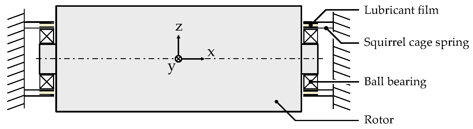
The studied rotor system consists of a massive shaft that is mounted at both ends within two SFDs with centring springs. The configuration of the rotor system is illustrated in Figure 1. The origin of the stationary coordinate system xyz lies in the centre of the rotor.
The rotor is considered as absolutely rigid and rotates with a constant angular speed. SFDs with squirrel cage springs are arranged symmetrically with respect to the central plane. The rotor is excited by an unbalance force. The effect of gravity is mitigated by prestressing the centring springs. In addition to SFD damping, the rotor is also affected by external damping from the environment. It is assumed that the damping is linear and proportional to the velocity. The damping force always acts in the opposite direction to the oscillations.
By employing the Lagrange equations of the second kind and under the defined assumptions, the lateral vibrations are governed by a set of two nonlinear equations of motion
where , , and are the mass, external damping, and stiffness matrix of the rotor system. The elements of the matrices are specified by the parameters of the rotor mass , damping coefficient , and stiffness of the single squirrel cage spring.
The nonlinear force generated by SFD is represented by the horizontal and vertical force components, which are arranged into the vector of the hydraulic damping forces
The vector is composed of the horizontal and vertical displacements, and
where and denote the first and second derivatives with respect to time, respectively.
The unbalance force, the gravity force, and the constant preload force of the centring springs are included in the vector of the applied forces:
where is the gravity acceleration, is the angular speed of the rotor rotation, and is the eccentricity and phase shift of the rotor unbalance, respectively, and represents the angular position of the line connecting the rotor and the journal centres.
The kinematic parameters of the rotor system under load are illustrated in a simplified cross-section view in Figure 2. Point G denotes the centre of gravity of the rotor. Point O denotes the centre of the damper sleeve and lies in the centre of the yz plane. The point OJ is the centre of the journal with a radius of R, and it is located on the r-axis of the rotating coordinate system tr, which have the origin located in point O. Additionally, a coordinate system with XYZ axes is introduced for computation of the hydraulic forces in the oil film.
The circular centred orbit of the synchronous precession motion is depicted in Figure 2 by the blue dashed line. In this case, the damper eccentricity e is a constant and the time derivation of the angular position is equal to the angular speed of the rotor rotation.
3. The Hydraulic Forces in SFD
To express the components of the hydraulic forces in SFD, the following assumptions are used:
- the pressure distribution in the damper is governed by the Reynolds equation for the short damper approximation, which is valid when the ratio of the damper length to the damper diameter is less than 0.5 (meaning that the flow in the circumferential direction is negligible),
- the pressure distribution is axially symmetric,
- the pressure boundary conditions are set to zero at the ends of the damper,
- the computation of the hydraulic forces considers the phenomenon of cavitation, using the π-film or Gumbel condition, and
- the assumptions of the classical theory of lubrication (see [34]).
Under these assumptions, the pressure p in the thin lubrication film is described by the relation
where is the dynamic viscosity of an oil, is the damper length. The axial coordinate and circumferential position in the oil film is defined, as indicated in Figure 2. The relative eccentricity is the ratio of the rotor eccentricity and the width of the damper gap in the centric position
In the rotating frame, the radial and tangential components of the hydraulic force are obtained by double integration of the pressure distribution (6) around the circumference and along the axial direction of the lubrication layer. The literature [34,35] considers the π-film cavitation and provides closed-form expression
The force components (8) are inserted into the equation of motion set up in the stationary reference frame (1) using a simple transformation stated in [6].
A summary of all the physical and geometric quantities used in the investigation is provided in Table 1. The external damping coefficient b is listed in the description of the relevant results.
4. Methods Used to Solve the Equation of Motion
The nonlinear hydraulic force depends on kinematic parameters and couples the vibration in the horizontal and vertical directions. As a result, the equation of motion (1) cannot be analytically solved, and numerical approaches must be employed.
According to the literature, the numerical solution of the response curve may encounter problems, as identified by other researchers [5,6,7,16,17,18,19,20] and through our own computational experiences. These problems are related to: (i) the presence of regions of multiple solutions, (ii) the hysteresis phenomenon due to the dependence of the damping force on the sweep direction of the rotational speed, (iii) the phenomenon of the disconnected branch of the response curve (also called isolated solution [5]), (iv) the ability of the time integration methods to compute both nonsynchronous [5,33] and stable synchronous [5,6,7,8] solution, (v) the possibility to compute both stable and unstable solution branches with methods using series approximation [6,7,36,37], and (vi) the sensitivity of the response to the choice of initial conditions or initial estimates of the solution.
Various methods for the solution and analysis of the nonlinear equation of motion (1) can be employed, each with its advantages, disadvantages, and limitations. To understand the vibration response behaviour of the rotor equipped with SFDs, the method of computation of the synchronous response with a circular centred orbit, HBM combined with continuation technique, and the time integration method were employed.
In literature [7,38] the shooting method, the trigonometric collocation method, and others are used to determine the steady-state solution.
4.1. Computation of the Synchronous Response with a Circular Centred Orbit
In the case of a rotor system, which is not subjected to a constant force and performs a circular motion around the centre position at the same frequency as the rotor rotational speed, this method can be used. It is a powerful technique when applied to the rigid and Jeffcott rotor models, as it requires minimal computational effort.
To determine the vibration response, the equations of motion (1) in the fixed coordinate system are transformed into the dimensionless form [8] in the rotating coordinate system
The relations for the damping ratio , the dimensionless mass unbalance , the dimensionless expressions for the external force , radial , and tangential component of the damper force are introduced:
The dimensionless speed and time are defined with the natural frequency
and the first and second derivatives with respect to the nondimensional time have the following form:
By introducing the nondimensional SFD constant [8]
four parameters (, , , ) describing the hydraulic force can be reduced into one. This further simplifies the equations of motion in Equations (9) and (10) and reduces the number of physical parameters. The value of the dimensionless SFD constant and unbalance of the investigated rotor is listed in Table 1.
The following conditions for the steady-state motion are assumed: (i) the circular orbit has a constant relative eccentricity , hence , (ii) the angular position , therefore and , and (iii) the damper is perfectly centred . As a result, the nondimensional equations of motion in Equations (9) and (10) in the rotating frame are reformulated as a nonlinear algebraic equation
where the dimensionless components and of the hydraulic force are a function of the dimensionless parameters.
In the case of the short damper approximation, the components of hydraulic force in Equation (8) are expressed in a closed form. The nonlinear algebraic Equation (15) can be transformed into a fourth-order polynomial. The promise of this method lies in the transformation of the differential Equations (9) and (10) into a polynomial with coefficients that are functions of the relative eccentricity.
As outlined in Equation (15), the steady-state response is described by five parameters: the relative eccentricity , damping ratio , the dimensionless mass unbalance , speed , and SFD constant . The solution for is found by determining the real roots of the polynomial equation within the range of rotor eccentricity . The clockwise and counterclockwise directions of the rotor rotation are defined by the positive and negative roots of the dimensionless speed.
The set of trigonometric Equations (16) and (17) defines the phase shift of the unbalance , which is expressed from the equations of motion (9), (10) under the assumption of a circular orbit and steady-state motion
4.2. Harmonic Balance Method
The HBM uses truncated Fourier series for solving the nonlinear differential equations by approximating the steady-state solution [36,37] with a finite number of harmonic terms with amplitude coefficients and frequencies.
The HBM involves approximating [36] the vectors of unknown kinematic parameters , the vector of nonlinear hydraulic forces , and the vector of external forces in the equation of motion (1) with the terms of Fourier series:
where , , and are Fourier coefficients of the amplitude vector of the displacements, hydraulic, and external forces. The number of harmonic terms is denoted , the imaginary unit is , and the optional integer parameter allows to accommodate possible subharmonic multiples of the rotor rotational speed .
By substituting relations (18) into the equation of motion (1), a set of nonlinear algebraical equations is obtained:
where the matrix of dynamical stiffness have the form
The nonlinear set of algebraical equations (19) is solved for the unknown Fourier coefficients by the Newton-Raphson like method. In each iteration step, the Alternating Frequency-Time Scheme [37] is used to approximate the displacements in the time domain and evaluate the nonlinear force.
The stable and unstable vibration response is determined by means of the continuity technique. The computational procedure uses a predictor-corrector method called the arc length method.
In the corrector step, the nonlinear algebraical Equation (19) is parameterized with an additional equation [38]
where is the arc-length parameter, and are values in the current step, and and denote values from the previous continuation step. The predictor step uses a secant predictor, where guess values for the following step are extrapolated from the two previous steps.
The set of nonlinear equations (19) and the parametrization condition, Equation (21), often have elements with different orders of magnitude and appropriate scaling [37] should be applied.
The vibration stability of the approximated solution in relations (18) is assessed by the application of Floquet theory on the perturbed equations of motion [39,40]. The vector of nonlinear hydraulic forces is expanded into the Taylor series in the neighbourhood of the phase trajectory with omitting the higher terms:
where , are Jacobi matrices of partial derivations and , are the vectors of deviations of displacements and velocities, respectively.
From the perturbed equation of motion [40], one can subtract the equation of motion of the unperturbed motion (1) and the final form of the kinematic deviations in the state space is expressed in the form
where are the unity and zeros matrices, respectively.
The elements of Jacobi matrices (23), assembled for the steady-state response are periodic functions of time, the same as the state space matrix in Equation (24). As a result, Floquet theory uses the concept of the transition matrix [38,39,40,41] to examine vibration stability. If all eigenvalues of the transition matrix are located inside the unit circle, the steady-state response is stable. The type of instability is determined by the location of the eigenvalues crossing the unit circle [7,38].
For the calculation of the vibration response and its stability assessment, the authors of the article developed original computational procedures, as described in the paper [42]. Procedures were verified on a small mechanical system with cubic nonlinearity and a rotor system with SFDs with hundreds of degrees of freedom.
4.3. The Time Integration Method
The time integration methods are used to solve the nonlinear equations of motion (1) for both transient and steady-state responses. Unlike the HBM, these methods do not require assumptions about the frequency spectra of the computed response or the type of journal motion. However, the time integration is more time-consuming than using other presented methods.
In the rotor response, multiple solutions can coexist over a certain range of speeds and the time integration can determine only the stable branch of a solution. The time integration method can be employed to assemble basins of attraction, which describe the long-time behaviour of the response for various sets of initial conditions.
The explicit Runge-Kutta (4,5) formula, implemented as the Dormand-Prince algorithm in the MATLAB software [43], was used. The time integration was set to a level of precision where reducing the time stepper to half did not result in a noticeable change in the determined response. The steady-state response computed by other methods was verified by the time integration method.
5. Computational Simulation Results and Discussion
The results are organized into four sections. The first section deals with the investigation of the effect of damping forces on the steady-state response under the assumption of circular centred orbit. Both stable and unstable synchronous responses are identified. The second section describes the nonsynchronous response and the conditions of its emergence. The third section provides basins of attraction to demonstrate the effect of the choice of the initial conditions on the response character. Finally, the fourth section deals with the presence of isolated solutions in the frequency response and provides information on the regions where they occur.
5.1. The Synchronous Response and the Stability Assessment
The frequency response curve for the investigated rotor is depicted in Figure 3. The response curve is composed of two discontinuous curves and shows the behaviour of the system with stiffening properties. One can observe that the nonlinear hydraulic forces have the dominant effect in the region of resonance. The resonant peak is shifted and bent in the direction of increasing rotational speed. There are regions of multiple solutions for a single rotational speed, indicating unstable branches of the frequency response curve. Hysteresis behaviour is also present for the increasing/decreasing rotational speed.
The three critical points divide the response curve into four regions denoted as A, B, C, and D. In Figure 3, the points are displayed as green circles. According to Floquet theory [38], the bifurcation points are of the saddle-node type, see Figure 4 and Figure 5.
In region A, the response of the rotor exhibits a circular orbit, and the vibration of the rotor is stable, as determined by Floquet theory. In region B, three different circular orbits are possible. Both orbits with the largest and smallest eccentricity are stable, while the branch in between represents an unstable response and is marked by a dashed line. The following region C has only a single stable solution. In the last region, denoted as D, multiple solutions appear. The solution with large eccentricity is isolated and its detailed view is depicted in Figure 3b. The isolated solution arises at the saddle-node point at a certain angular speed value and has two branches. The vibration response is unstable for the lower branch, denoted by the dashed line.
The blue curve in Figure 3 was obtained from the solution of the nonlinear algebraic Equation (15) derived with the assumption of a synchronous circular orbit. The steady-state response, marked with the “+“ symbol, was obtained by the direct time integration and the red “x“ symbol denotes the solution provided by the HBM combined with the arc length method.
The equations of motion (1) were solved using the MATLAB software environment. The time integration was performed using the ode45 routine [43] with the relative and absolute tolerance [43] set to 1·10−12 and 1·10−15, respectively. The calculation was done with an upward and downward sweep of the rotational speed. In Figure 3, the direction of the sweep is indicated by black and green arrows. The initial conditions for the current sweep step were obtained from the previous step. The form of the obtained response curve demonstrates that the direct time integration method is not suitable to compute unstable branches, as depicted in Figure 3.
The HBM, combined with the use of arc length continuation, was able to identify both stable and unstable regions. The isolated solution was identified by setting the initial conditions near the searched solution. The response was explored using 8 harmonic terms, a 10x oversampling factor, and an arc length parameter of 1 × 10⁻². The norm of the relative solution error was found to be less than 7 × 10⁻¹⁴ across the investigated range of rotational speed.
It has been confirmed that all applied methods for identifying the response converge to the same solution. However, the methods differ in terms of computational and time effort, where time integration is the most expensive.
Figure 4 displays the dependencies of the real (Figure 4a) and imaginary (Figure 4b) parts of the largest eigenvalue of the transition matrix on the nondimensional speed. The saddle-node bifurcation was identified as the real part of the leading eigenvalue crossing the unit circle in the location of the positive real axis. The variation of the maximum module of the eigenvalues on the nondimensional speed is depicted in Figure 5a,b. It is evident that the unstable response occurred when the largest eigenvalue modulus exceeds unity. Figure 5b illustrates the situation when the isolated solution almost connects to the resonance peak. The actual connection occurs for the nondimensional unbalance value of 0.417315.
The qualitative changes in the response curves as a result of varying the nondimensional unbalance are depicted in Figure 6a. The computations were carried out for SFD with the nondimensional constant of 0.25. As the unbalance increases, the isolated solution gets closer to the resonant peak, and at a value of 0.417315, it connects to the resonant peak. In the vicinity of this point, the nonlinear forces have the strongest influence on the response. In case of large unbalance, the journal can exhibit synchronous response with a circular orbit with an eccentricity close to the damper clearance.
In Figure 6b, the bent of the resonance peak towards the higher rotational speeds is shown for the higher value of the dimensionless unbalance of 0.7. Additionally, the shift of the isolated solution to much higher rotational speeds is demonstrated for a small unbalance value of 0.2.
5.2. The Nonsynchronous Response
The simulations show that the rotor system with SFDs can exhibit not only a synchronous response with a circular orbit but also a nonsynchronous response. The direct time integration method of the equation of motion (1) must be used to compute this type of response. In Figure 7, the blue curve denotes the nonsynchronous response computed at the nondimensional angular speed of a value of 8.7. The black curve represents the contour of the damper clearance, and the red curves illustrate the circular orbits.
The behaviour of the computed response is assessed with the Poincaré section, which consists of intersection points of the trajectory with a section plane at the time period. These points are determined at constant time intervals, corresponding to the period of excitation force. In Figure 7, the points of the Poincaré section are drawn with a green colour. The Poincaré section is constructed for the time history of displacements over 6000 times the period of the excitation force and the region of the plotted trajectory is filled with a curve of blue colour. The resulting set of intersection points in the Poincaré section appears as a continuous closed curve. Therefore, it can be assumed that the nonsynchronous motion has a quasiperiodic character.
The time history of the displacement in the horizontal direction of the nonsynchronous motion at a nondimensional angular speed of 8.7 is shown in Figure 8. The dependence in Figure 8a is plotted for the time of 40 excitation periods and Figure 8b shows a detailed view. The time dependences exhibit a typical quasiperiodic motion.
The frequency components calculated from the time history using the discrete Fourier transform (DFT) are shown in Figure 9. The response includes the rotational frequency f1 = 1 (in the nondimensional form), a subharmonic component f2 = 0.2974, and several of their difference frequencies. The response is a combination of two independent motions, with the ratio of their frequencies being an irrational number.
The trajectory in the state space with the Poincaré section is presented in Figure 10. In Figure 10a, a case with a nondimensional speed of 8.5328 is shown, when the nonsynchronous vibrations occur. Figure 10b depicts the case for a speed value of 10, which is at the end of the investigated region. The kinematic parameters are plotted in the state space for the duration 6000 times the excitation period long. The individual trajectories cannot be clearly distinguished because the envelope of the trajectory is filled with blue curves in Figure 10.
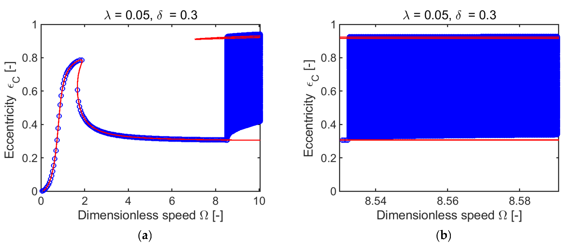
The frequency response curve and the bifurcation diagram of the nonsynchronous response are drawn in Figure 11. The points of the bifurcation diagram are plotted with the blue circle symbols.
The direct time integration with zero initial conditions was used for computing a nonsynchronous response. The integration was performed with a very fine nondimensional speed step in the vicinity of the origin of the nonsynchronous response. It was found that the origin of the nonsynchronous response occurs in the interval 8.5322–8.5327 of nondimensional speed and has a quasiperiodic character.
5.3. The Basins of Attraction
The solution type of the response is determined by the choice of initial conditions. The response is calculated using the direct time integration method.
Unless otherwise specified, the initial conditions for velocities are set to zeros. The initial displacements are selected from the set of points evenly distributed in the damper clearance up to 98% of its size. Figure 12, Figure 13b and Figure 14b are constructed of approximately 8000 points of the initial displacement values. A comparison of a coarser and a finer mesh of points for the construction of basins of attraction can be seen in Figure 12a and Figure 13a.
The influence of the initial displacements to characterize the long-time behaviour of solutions is illustrated in Figure 12. The computed basins of attraction are composed of two possible solutions. The set of points coloured red corresponds to a response with a circular orbit of a smaller radius, and the green-coloured points correspond to a response with a larger circular orbit.
The investigated nondimensional speeds are selected from within the B region on the frequency response curve. At the nondimensional speed of 1.715, located near the lower bifurcation point, the solution converges to the larger circular orbit in 68% of cases. Conversely, at the nondimensional speed of 1.838, the solution converges to the smaller orbit in 82% of cases.
In the case of the nondimensional speed of 1.780, located almost in the middle section of the unstable vibration response, the solution converges to the smaller orbit in 61% of cases, and in 39% of cases to the larger one, as shown in Figure 13a. It was found that the shape of basins of attraction also depends on the choice of initial velocities. Figure 13b shows the basins of attraction for the chosen initial conditions of the velocity with the assumption of a circular orbit. The solutions were attracted to the circular orbit with a smaller radius in 31% of cases and to the larger radius in 69%.
Three values of the dimensionless speed (7.1, 8.0, and 8.5) were chosen. The responses were obtained through time integration, assuming zero initial velocities and using the initial displacements from the grid of points shown in Figure 12. The basins of attraction identified a single solution for these three rotational speeds.
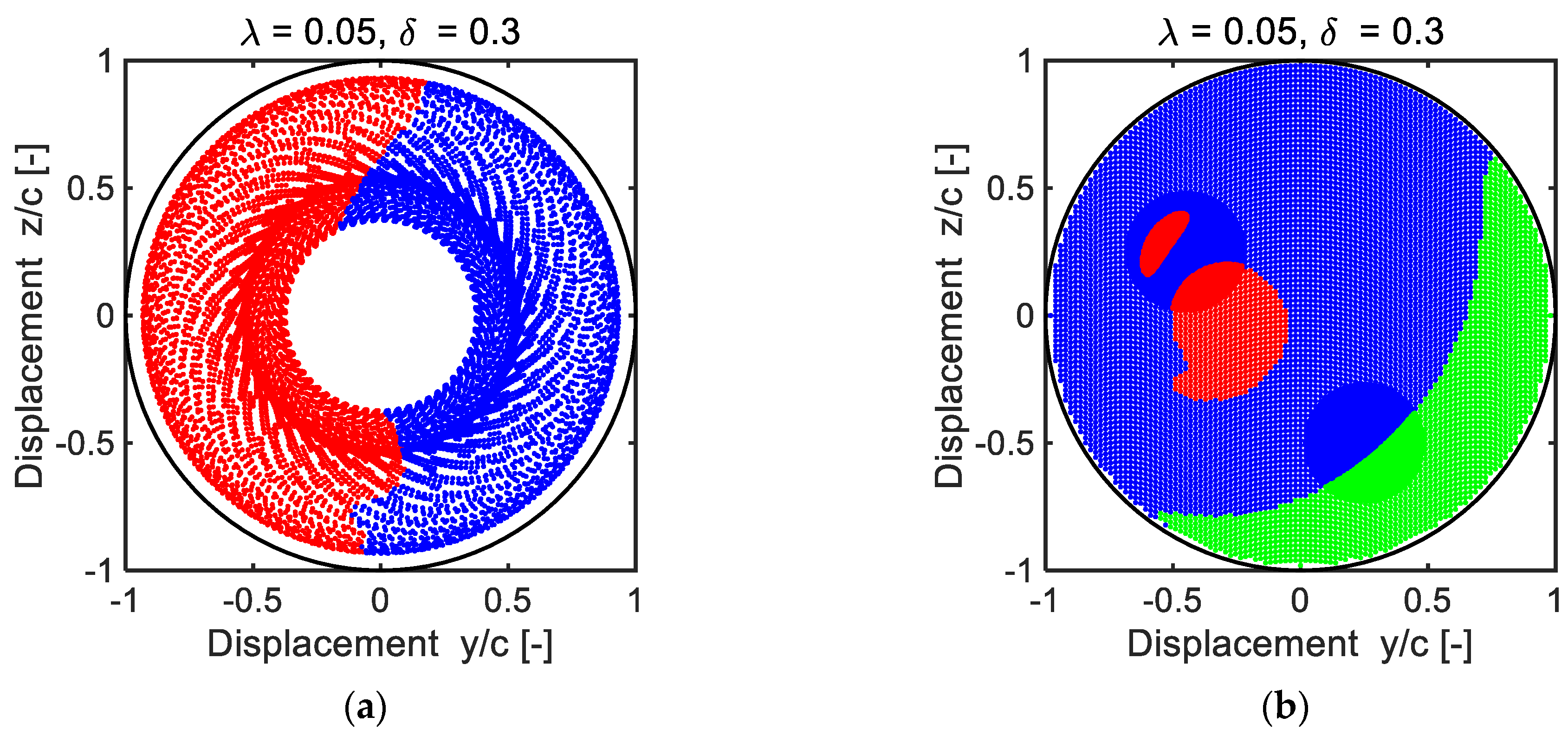
The origin of nonsynchronous response occurs at the nondimensional speed of 8.5327 located in the D region, as shown in Figure 11. For this reason, basins of attraction for the initial velocities of zero and non-zero values were studied, and the results are shown in Figure 14. When considering the zero initial velocities, two basins of attraction were identified, see Figure 14a. The response with a smaller orbit radius occurs in 49% of the cases and is marked by the red colour. A quasiperiodic response occurs in 51% and is indicated by the blue colour. The long-time convergence to a given solution was determined for the response after 500 times the period of the excitation force.
On the other hand, with nonzero initial velocities, three basins of attraction were identified, depicted in Figure 14b. The non-zero initial velocities were specified with the assumption of a circular motion. A synchronous response with a small orbit radius occurs in 8% (marked by the red colour), a response with a large orbit radius in 21% (marked by the green colour), and a nonsynchronous quasiperiodic response in 71% (marked by the blue colour).
In summary, when the initial velocity is zero, two types of solutions can be observed, and when the initial velocity is non-zero, three types of solutions can be observed.
Figure 15 shows the basins of attraction for the nondimensional speed of 9.0. In Figure 15a, the initial velocities are set to zero and the initial displacements are taken from solutions of the time-dependent quasiperiodic response. The distribution of the initial displacements is determined by the number of samples selected from the quasiperiodic response. The response was computed using the time integration for a duration of 1200 times the excitation force period. The basins of attraction are determined with the last 600 periods, containing approximately 10000 of the time samples.
The non-zero initial velocities with the assumption of a circular motion were specified for the computation of the basins of attraction depicted in Figure 15b. In the vicinity of a border of the basins of attraction, two circular areas were selected for the recalculation of responses, as seen in Figure 15b. It can be assumed that the border of the basins of attraction between the different solutions is smooth, as shown in Figure 15b.
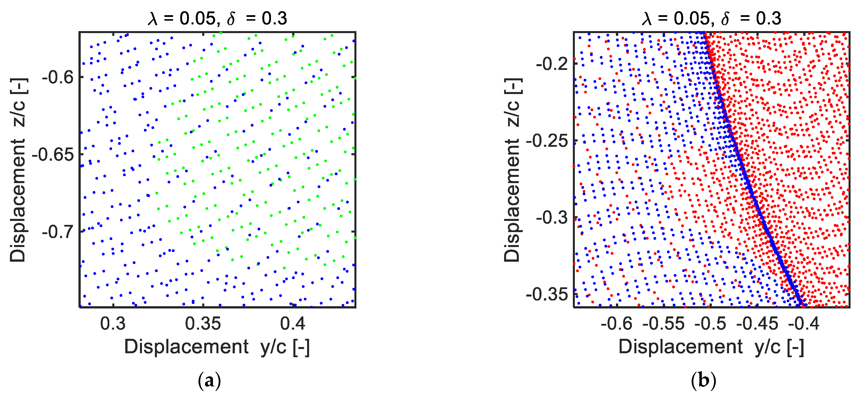
The initial conditions for the assessment of the basins of attraction in Figure 16 and Figure 17 are based on the time history of the quasiperiodic response for a nondimensional speed of 9.0. The number of initial points used differs between Figure 16a and Figure 16b. The basins of attraction depict solutions for a small (red colour) orbit radius and a large (green colour) orbit radius, as well as a nonsynchronous quasiperiodic response (blue colour).
It can be seen that the regions of the basins of attraction can contain one solution or a combination of two solutions (as shown in Figure 17a). The border between the basins of the attraction does not have a clear structure, as seen in Figure 17b. These results are qualitatively different from results (see Figure 15b) obtained when using initial conditions that assume circular motion.
5.4. The Conditions for Isolated Solution
A study was conducted to examine the effect of the dimensionless SFD constant and unbalance on the response with an isolated solution. The results identified the conditions and parameters that cause the presence of nonsynchronous response.
In Figure 18, the coloured region indicates the conditions for the presence of an isolated solution in the frequency response curve. The contours are plotted for a range of the nondimensional SFD parameter from 0.01 to 1.5, and unbalance from 0.05 to 0.95. The coloured region in Figure 18 has an upper (denoted with the symbol u) and a lower (denoted with the symbol l) boundary. The upper boundary is primarily determined by the value of unbalance and represents the point at which the resonance peak and the isolated solution merge. The lower boundary is defined by the maximum permitted value of the dimensionless speed, which is 20 in this case.
The maximum permitted value of the nondimensional rotational speed was established to ensure that the rotor does not suffer mechanical damage during operation. It affects the size of the region where the isolated solution can originate. When a higher maximum speed is allowed, the area in which the isolated solution can originate will be larger.
It was found that the external damping not only affects the resonance peak, causing it to shift and decrease in amplitude, but also shifts the origin of the isolated solution to higher speeds for a given unbalance, as demonstrated by the upper boundary in Figure 18a,b. Furthermore, when the dimensionless SFD constant is less than 1.0, the range of unbalance values for which an isolated solution can exist is larger. However, when the dimensionless SFD constant is greater than 1.0, the range of unbalance values is reduced into a narrow region.
This region defines a specific range of combinations of the dimensionless SFD constants and unbalance values for the presence of the isolated solution in the frequency response. The conducted numerical research shows that the nonsynchronous solution can arise only in the frequency response region with the isolated solution. Operating the rotor above the lower boundary region in Figure 18 poses a risk as it can result in nonsynchronous oscillations or synchronous motion with the circular centred orbit with a large radius.
6. Conclusions
The article investigates the frequency response and vibration stability of the rigid rotor with unbalance, coupled with SFDs. To analyse the rotor’s response, three methods were used: the computation of the synchronous response with a circular centred orbit, the harmonic balance method, and the direct time integration method. All three methods accurately computed the frequency response curve, and the results were in good agreement. The stability of the induced vibrations was evaluated by means of the Floquet theorem. New computational procedures were developed to solve the equation of motion and assess vibration stability.
The results of the computational simulations show that the nonlinear damping forces greatly impact the motion of the rotor, particularly in the resonance region for high values of the unbalance. It was verified that the frequency response curve is composed of four regions with varying numbers of solutions, where multiple branches of the frequency response are unstable. Techniques such as time series analysis, Fourier transformation, trajectory analysis in state space, Poincaré sections, and bifurcation diagrams were used to study the nonlinear behaviour.
A substantial amount of the newly presented work focuses on illustrating how initial conditions can affect the long-time behaviour of the response. The study presents basins of attraction for various values of the nondimensional speed. It has been proven that the basins of attractions are sensitive to the choice of initial velocity values. The regions of attraction can contain more than one solution, and the borders between them can be either smooth or without a clear structure.
The simulation results indicate that the nonsynchronous response has a quasiperiodic character and occurs solely at rotational speeds that exceed the speeds where the isolated solution originates. The nonsynchronous response is generally considered to be an undesirable behaviour. Therefore, a new range of parameters for the dimensionless SFD constant, unbalance, and rotational speed was defined, which determines the conditions for the appearance of an isolated solution.
The results of the carried-out research are highly valuable for contemporary investigations of nonlinear vibrations, particularly for high-speed rotating machines coupled with SFDs.
Author Contributions
Conceptualization, M.M. and P.F.; methodology, M.M., J.Z. and P.F.; software, M.M. and P.F.; validation, P.F. and J.Z.; formal analysis, M.M., P.F. and J.Z.; investigation, P.F., J.Z. and M.M.; resources, M.M., P.F. and J.Z.; data curation, P.F. and M.M.; writing—original draft preparation, P.F. and M.M.; writing—review and editing, P.F., M.M. and J.Z.; visualization, M.M.; supervision, P.F. and J.Z.; project administration, P.F. and M.M.; funding acquisition, M.M. and P.F. All authors have read and agreed to the published version of the manuscript.
Funding
The authors are grateful for the support and funding provided by the Ministry of Education, Youth and Sports of the Czech Republic through the e-INFRA CZ (ID:90140), the Doctoral Grant Competition of Technical University of Ostrava (No. CZ.02.2.69/0.0./0.0/19_073/0016945) within the Operational Programme Research, Development and Education, under project DGS/TEAM/2020-033, the Support for Science and Research in the Moravian-Silesian Region (No. RRC/02/2020), and the Project of Specific University Research (No. SP2022/26).
Institutional Review Board Statement
Not applicable.
Informed Consent Statement
Not applicable.
Data Availability Statement
Data sharing does not apply to this article.
Conflicts of Interest
The authors declare no conflict of interest.
References
- Pietra, L.D.; Adiletta, G. The Squeeze Film Damper over Four Decades of Investigations. Part I: Characteristics and Operating Features. Shock Vib. Dig. 2002, 34, 3–26. [Google Scholar]
- Pietra, L.D.; Adiletta, G. The Squeeze Film Damper over Four Decades of Investigations. Part II: Rotordynamic Analyses with Rigid and Flexible Rotors. Shock Vib. Dig. 2002, 34, 97–126. [Google Scholar]
- Chen, H.; Hou, L.; Chen, Y.; Yang, R. Dynamic Characteristics of Flexible Rotor with Squeeze Film Damper Excited by Two Frequencies. Nonlinear Dyn. 2017, 87, 2463–2481. [Google Scholar] [CrossRef]
- Chen, H.; Hou, L.; Chen, Y. Bifurcation Analysis of a Rigid-rotor Squeeze Film Damper System with Unsymmetrical Stiffness Supports. Arch. Appl. Mech. 2017, 87, 1347–1364. [Google Scholar] [CrossRef]
- Zhu, C.S.; Robb, D.A.; Ewins, D.J. Analysis of the Multiple-solution Response of a Flexible Rotor Supported on Non-linear Squeeze Film Dampers. J. Sound Vib. 2002, 252, 389–408. [Google Scholar] [CrossRef]
- Zhao, J.Y.; Linnett, I.W.; McLean, L.J. Subharmonic and Quasi-Periodic Motions of an Eccentric Squeeze Film Damper-Mounted Rigid Rotor. ASME J. Vib. Acoust. 1994, 116, 357–363. [Google Scholar] [CrossRef]
- Zhao, J.Y.; Linnett, I.W.; McLean, L.J. Stability and Bifurcation of Unbalanced Response of a Squeeze Film Damped Flexible Rotor. ASME J. Tribol. 1994, 116, 361–368. [Google Scholar] [CrossRef]
- Taylor, D.L.; Kumar, B.R.K. Closed-Form, Steady-State Solution for the Unbalance Response of a Rigid Rotor in Squeeze Film Damper. ASME J. Eng. Power 1983, 105, 551–556. [Google Scholar] [CrossRef]
- Gooding, W.J.; Meier, M.A.; Gunter, E.J.; Key, N.L. Nonlinear Response and Stability of an Experimental Overhung Compressor Mounted with a Squeeze Film Damper. In Proceedings of the ASME Turbo Expo 2020 Turbomachinery Technical Conference and Exposition GT2020, London, UK, 22–26 June 2020. [Google Scholar]
- Adiletta, G.; Pietra, L.D. Experimental Study of a Squeeze Film Damper with Eccentric Circular Orbits. ASME J. Tribol. 2006, 128, 365–377. [Google Scholar] [CrossRef] [Green Version]
- Hua, J.; Wan, F.; Xu, Q. Numerical and Experimental Studies on Nonlinear Dynamic Behaviors of a Rotor-Fluid Film Bearing System with Squeeze Film Dampers. ASME J. Vib. Acoust. 2001, 123, 297–302. [Google Scholar] [CrossRef]
- Botman, M. Experiments on Oil-Film Dampers for Turbomachinery. ASME J. Eng. Power 1976, 98, 393–399. [Google Scholar] [CrossRef]
- Chen, X.; Ren, G.; Gan, X. Dynamic Behavior of a Flexible Rotor System with Squeeze Film Damper Considering Oil-film Inertia Under Base Motions. Nonlinear Dyn. 2021, 106, 3117–3145. [Google Scholar] [CrossRef]
- Adiletta, G. An Insight into the Dynamics of a Rigid Rotor on Two-lobe Wave Squeeze Film Damper. Tribol. Int. 2017, 116, 69–83. [Google Scholar] [CrossRef]
- Ferfecki, P.; Zapoměl, J.; Šofer, M.; Pochylý, F.; Fialová, S. Numerical Computation of the Damping and Stiffness Coefficients of the Classical and Magnetorheological Squeeze Film damper. In Proceedings of the MATEC Web of Conferences 157, Machine Modelling and Simulations 2017, Sklené Teplice, Slovak Republic, 5–8 September 2017. [Google Scholar] [CrossRef]
- Chen, H.; Chen, Y.; Hou, L.; Li, Z. Bifurcation Analysis of Rotor–squeeze Film Damper System with Fluid Inertia. Mech. Mach. Theory 2014, 81, 129–139. [Google Scholar] [CrossRef]
- Chang-Jian, C.W. Bifurcation and Chaos Analysis of the Porous Squeeze Film Damper Mounted Gear-bearing System. Comput. Math. Appl. 2012, 64, 798–812. [Google Scholar] [CrossRef] [Green Version]
- Inayat-Hussain, J.I.; Mureithi, N.W. Transitions to Chaos in Squeeze-film Dampers. Commun. Nonlinear Sci. Numer. Simul. 2006, 11, 721–744. [Google Scholar] [CrossRef]
- Inayat-Hussain, J.I.; Kanki, H.; Mureithi, N.W. On the Bifurcations of a Rigid Rotor Response in Squeeze-film Dampers. J. Fluids Struct. 2003, 17, 433–459. [Google Scholar] [CrossRef]
- Gao, T.; Cao, S.; Sun, Y. Nonlinear Dynamic Behavior of a Flexible Asymmetric Aero-engine Rotor System in Maneuvering Flight. Chin. J. Aeronaut. 2020, 33, 2633–2648. [Google Scholar] [CrossRef]
- Hamzehlouia, S.; Behdinan, K. Squeeze Film Dampers Supporting High-speed Rotors: Rotordynamics. Proc. Inst. Mech. Eng. Part J J. Eng. Tribol. 2021, 235, 1–14. [Google Scholar] [CrossRef]
- Hamzehlouia, S.; Behdinan, K. Squeeze Film Dampers Executing Small Amplitude Circular-Centered Orbits in High-Speed Turbomachinery. Int. J. Aerosp. Eng. 2016, 2016, 5127096. [Google Scholar] [CrossRef] [Green Version]
- Hamzehlouia, S.; Behdinan, K. Squeeze Film Dampers Supporting High-speed Rotors: Fluid Inertia Effect. Proc. Inst. Mech. Eng. Part J J. Eng. Tribol. 2020, 234, 18–32. [Google Scholar] [CrossRef]
- Heidari, H.; Ashkooh, M. The Influence of Asymmetry in Centralizing Spring of Squeeze Film Damper on Stability and Bifurcation of Rigid Rotor Response. Alex. Eng. J. 2016, 55, 3321–3330. [Google Scholar] [CrossRef] [Green Version]
- Shaik, K.; Dutta, B.K. Stability Analysis of Horizontal Symmetric Flexible Rotor Mounted on Hydrodynamic Bearing and Squeeze Film Damper Using Analytical Approach. Tribol. Int. 2021, 158, 106924. [Google Scholar] [CrossRef]
- Shaik, K.; Dutta, B.K. Tuning Criteria of Nonlinear Flexible Rotor Mounted on Squeeze Film Damper Using Analytical Approach. J. Vib. Eng. Technol. 2021, 9, 325–339. [Google Scholar] [CrossRef]
- Zapoměl, J.; Ferfecki, P.; Kozánek, J. The Mathematical Model for Analysis of Attenuation of Nonlinear Vibration of Rigid Rotors Influenced by Electromagnetic Effects. J. Sound Vib. 2019, 443, 166–177. [Google Scholar] [CrossRef]
- Zapoměl, J.; Ferfecki, P. The Oscillation Attenuation of an Accelerating Jeffcott Rotor Damped by Magnetorheological Dampers Affected by the Delayed Yielding Phenomenon in the Lubricating Oil. ASME J. Vib. Acoust. 2017, 140, 011017. [Google Scholar] [CrossRef]
- Ferfecki, P.; Zapoměl, J.; Gebauer, M.; Polreich, V.; Křenek, J. A Computational Fluid Dynamics Investigation of the Segmented Integral Squeeze Film Damper. In Proceedings of the MATEC Web of Conferences 254, XXIII Polish-Slovak Scientific Conference on Machine Modelling and Simulations, Rydzyna, Poland, 4–7 September 2018. [Google Scholar] [CrossRef]
- Heidari, H.R.; Safarpour, P. Design and Modeling of a Novel Active Squeeze Film Damper. Mech. Mach. Theory 2016, 105, 235–243. [Google Scholar] [CrossRef]
- Zhang, Y.; He, L.; Yang, J.; Wan, F.; Gao, J. Vibration Control of an Unbalanced Single-Side Cantilevered Rotor System with a Novel Integral Squeeze Film Bearing Damper. Appl. Sci. 2019, 9, 4371. [Google Scholar] [CrossRef] [Green Version]
- Shi, M.; Yang, Y.; Deng, W.; Wang, J.; Fu, C. Analysis of Dynamic Characteristics of Small-Scale and Low-Stiffness Ring Squeeze Film Damper-Rotor System. Appl. Sci. 2022, 12, 7167. [Google Scholar] [CrossRef]
- Li, X.; Taylor, D.L. Nonsynchronous Motion of Squeeze Film Damper Systems. ASME J. Tribol. 1987, 109, 169–176. [Google Scholar] [CrossRef]
- Hori, Y. Hydrodynamic Lubrication, 6th ed.; Springer-Verlag: Tokyo, Japan, 2006; pp. 1–231. [Google Scholar]
- Ri, K.; Ri, Y.; Yun, C.; Kim, K.; Han, P. Analysis of Nonlinear Vibration and Stability of Jeffcott Rotor Supported on Squeeze-film Damper by IHB Method. AIP Adv. 2022, 12, 025127. [Google Scholar] [CrossRef]
- Xie, L.; Baguet, S.; Prabel, B.; Dufour, R. Bifurcation Tracking by Harmonic Balance Method for Performance Tuning of Nonlinear Dynamical Systems. Mech. Syst. Signal Process. 2017, 88, 445–461. [Google Scholar] [CrossRef] [Green Version]
- Krack, M.; Gross, J. Harmonic Balance for Nonlinear Vibration Problems, 1st ed.; Springer: Cham, Switzerland, 2019; pp. 1–159. [Google Scholar]
- Seydel, R. Practical Bifurcation and Stability Analysis, 3rd ed.; Springer: New York, NY, USA, 2010; pp. 1–483. [Google Scholar]
- Ferfecki, P.; Zaoral, F.; Zapoměl, J. Using Floquet Theory in the Procedure for Investigation of the Motion Stability of a Rotor System Exhibiting Parametric and Self-Excited Vibration. J. Mech. Eng. 2019, 69, 33–42. [Google Scholar] [CrossRef] [Green Version]
- Zapoměl, J.; Kozánek, J.; Ferfecki, P. The Stability Investigation of Vibrations of Flexibly Supported Rigid Rotors Damped by Hybrid Magnetorheological Damping Elements. In Proceedings of the Engineering Mechanics 2013, Svratka, Czech Republic, 13–16 May 2013. [Google Scholar]
- Zapoměl, J.; Ferfecki, P.; Forte, P. Analysis of the Steady State Unbalance Response of Rigid Rotors on Magnetorheological Dampers: Stability, Force Transmission and Energy Dissipation. Int. J. Appl. Mech. 2014, 06, 1450022. [Google Scholar] [CrossRef]
- Molčan, M.; Ferfecki, P.; Zapoměl, J. Efficient Numerical Computation of the Steady-state Response and Stability Analysis of the Rotor Systems with Squeeze Film Dampers. In Proceedings of the Engineering Mechanics 2020, Brno, Czech Republic, 24–25 November 2020. [Google Scholar] [CrossRef]
- The MathWorks Inc. MATLAB R2020b (9.9.0.1467703); The MathWorks Inc.: Natick, MA, USA, 2020. [Google Scholar]
Figure 1.
Scheme of the rigid rotor mounted in SFDs.

Figure 2.
Scheme of SFD geometry with the definition of reference frames.

Figure 3.
Frequency response curve (a) and detail of the isolated part (b); borders of regions are denoted by the red dashed lines and u, m, and l denote the upper, middle, and lower branches.
Figure 3.
Frequency response curve (a) and detail of the isolated part (b); borders of regions are denoted by the red dashed lines and u, m, and l denote the upper, middle, and lower branches.

Figure 4.
The effect of the rotational speed on the maximum of real (a) and imaginary (b) part of the eigenvalues μ; the borders of regions are denoted by the red dashed lines and the unstable speed interval is marked by the red line.
Figure 4.
The effect of the rotational speed on the maximum of real (a) and imaginary (b) part of the eigenvalues μ; the borders of regions are denoted by the red dashed lines and the unstable speed interval is marked by the red line.

Figure 5.
Dependence of the module of eigenvalues of the transition matrix on the different values of the nondimensional SFD constant and unbalance.
Figure 5.
Dependence of the module of eigenvalues of the transition matrix on the different values of the nondimensional SFD constant and unbalance.

Figure 6.
Frequency response curves for six values of the dimensionless unbalance (a) and for the expanded range of the dimensionless speed (b).
Figure 6.
Frequency response curves for six values of the dimensionless unbalance (a) and for the expanded range of the dimensionless speed (b).

Figure 7.
Nonsynchronous response (a) and the detail of its structure (b).

Figure 8.
Time history of the displacement in the horizontal direction of the nonsynchronous motion (a) and the detailed view (b).
Figure 8.
Time history of the displacement in the horizontal direction of the nonsynchronous motion (a) and the detailed view (b).

Figure 9.
The frequency spectrum of the dimensionless horizontal displacement (a) and velocity (b).

Figure 10.
The state space with the Poincaré section (denoted with green points) for the nondimensional speed of 8.5327 (a) and 10 (b).
Figure 10.
The state space with the Poincaré section (denoted with green points) for the nondimensional speed of 8.5327 (a) and 10 (b).

Figure 11.
The frequency response of the synchronous motion and the bifurcation diagram (a) and detail of the bifurcation diagram near the origin of the nonsynchronous response (b).
Figure 11.
The frequency response of the synchronous motion and the bifurcation diagram (a) and detail of the bifurcation diagram near the origin of the nonsynchronous response (b).

Figure 12.
Illustration of the basins of attraction for the nondimensional speed of 1.715 (a), 1.838 (b).
Figure 12.
Illustration of the basins of attraction for the nondimensional speed of 1.715 (a), 1.838 (b).

Figure 13.
The basins of attraction for the nondimensional speed of 1.780 as a result of the zero (a), and nonzero (b) initial velocities; the red/green points correspond to a smaller/larger orbit radius.
Figure 13.
The basins of attraction for the nondimensional speed of 1.780 as a result of the zero (a), and nonzero (b) initial velocities; the red/green points correspond to a smaller/larger orbit radius.

Figure 14.
The basins of attraction for the nondimensional speed of 8.5327 as a result of the zero (a) and nonzero (b) initial velocities; the red/green points correspond to a smaller/larger orbit radius and the blue points correspond to a quasiperiodic response.
Figure 14.
The basins of attraction for the nondimensional speed of 8.5327 as a result of the zero (a) and nonzero (b) initial velocities; the red/green points correspond to a smaller/larger orbit radius and the blue points correspond to a quasiperiodic response.

Figure 15.
The basins of attraction for the nondimensional speed of 9.0 for zero initial velocities and displacements based on a quasiperiodic response (a) and for the assumption of a circular motion (b).
Figure 15.
The basins of attraction for the nondimensional speed of 9.0 for zero initial velocities and displacements based on a quasiperiodic response (a) and for the assumption of a circular motion (b).

Figure 16.
The basins of attraction for the nondimensional speed of 9.0 and the initial conditions, based on a quasiperiodic response, with 10,000 (a) and 90,000 (b) time samples.
Figure 16.
The basins of attraction for the nondimensional speed of 9.0 and the initial conditions, based on a quasiperiodic response, with 10,000 (a) and 90,000 (b) time samples.

Figure 17.
Detail of the structure of basins of attraction for D1 (a) and D2 (b) regions.

Figure 18.
The effect of the dimensionless parameters on the presence of an isolated solution for the case without (a) and with (b) external damping.
Figure 18.
The effect of the dimensionless parameters on the presence of an isolated solution for the case without (a) and with (b) external damping.


Table 1.
Parameters of the rotor and SFD.
| Name | Symbol | Value | Dimension |
|---|---|---|---|
| Rotor mass | m | 285 | kg |
| Stiffness of the single squirrel cage spring | k | 25 | MN |
| Balance quality grade according to ISO 1940-1 | Q | 6.3 | - |
| Gravity acceleration | g | 9.81 | m s−2 |
| Dynamic viscosity of the oil ISO VG 46 | η | 0.03 | Pa s |
| Damper length | L | 20 | mm |
| Damper radius | R | 25 | mm |
| Width of the damper gap | c | 100 | μm |
| Dimensionless unbalance | δ | 0.3 | - |
| Dimensionless SFD constant | λ | 0.0503 | - |
Disclaimer/Publisher’s Note: The statements, opinions and data contained in all publications are solely those of the individual author(s) and contributor(s) and not of MDPI and/or the editor(s). MDPI and/or the editor(s) disclaim responsibility for any injury to people or property resulting from any ideas, methods, instructions or products referred to in the content. |
© 2023 by the authors. Licensee MDPI, Basel, Switzerland. This article is an open access article distributed under the terms and conditions of the Creative Commons Attribution (CC BY) license (https://creativecommons.org/licenses/by/4.0/).
Share and Cite
MDPI and ACS Style
Molčan, M.; Ferfecki, P.; Zapoměl, J. The Numerical Identification of Basins of Attraction for the Vibration Response of the Rigid Rotor with Squeeze Film Dampers. Appl. Sci. 2023, 13, 2864. https://doi.org/10.3390/app13052864
AMA Style
Molčan M, Ferfecki P, Zapoměl J. The Numerical Identification of Basins of Attraction for the Vibration Response of the Rigid Rotor with Squeeze Film Dampers. Applied Sciences. 2023; 13(5):2864. https://doi.org/10.3390/app13052864
Chicago/Turabian StyleMolčan, Michal, Petr Ferfecki, and Jaroslav Zapoměl. 2023. "The Numerical Identification of Basins of Attraction for the Vibration Response of the Rigid Rotor with Squeeze Film Dampers" Applied Sciences 13, no. 5: 2864. https://doi.org/10.3390/app13052864
Note that from the first issue of 2016, this journal uses article numbers instead of page numbers. See further details here.