1. Introduction
The rotors are frequently coupled with the stationary part by rolling element bearings. To avoid excessive or even unstable oscillations of rotating machines, the rolling element bearings are inserted in squeeze film dampers. Because of variable operating conditions, the rotors must often change their angular speed and pass through the resonance area, which induces their vibrations, which are of large amplitude. The controlled change in the damping effect in the rotor supports and represents a significant tool for its attenuation.
The rotors’ starting-up and running-down are important phases of their operation and realization of technological processes. Therefore, the behavior of rotors when changing their angular velocity in the vicinity of the critical speed is still the subject of intensive investigations. The first and second impulse theorems and the Lagrange equations of the second kind were used by Zapoměl and Ferfecki [
1,
2] to derive the equations of motion of a flexible accelerating rotor. The authors discussed the influence of additional inertia terms on rotor oscillation. The equations of motions of an accelerating rotor can also be obtained by extending procedures presented by Gasch et al. in [
3]. The methodology of vibration-based crack diagnostics of rotors speeding up through the resonance area is reported by Sawicki et al. [
4]. Diken and Alnefaie [
5] used computational simulations to perform the study on the vibration of a starting-up Jeffcott rotor. The authors concluded that the overshoot of the start-up speed significantly increases the value of the maximum rotor lateral displacement. Nowald et al. [
6] dealt with the simulation of the transient run-up of rotors supported by fluid film bearings. The model they developed consists of a rotor represented by a flexible multibody system and bearings discretized with finite elements. The conducted research was aimed at the cognition of different behavior of two design variants of a turbocharger when the bearings were either fully submerged in the oil bath or worked in the air environment. Wei et al. [
7] performed a transient analysis of a speed-varying rotor, focusing on the influence of uncertain parameters. The effort was aimed at reducing errors in calculations. Fu et al. [
8] focused on the response analysis of an accelerating overhung rotor affected by random and uncertain values of a number of physical parameters. The developed approach provides guidance for the accurate transient dynamic analysis of engineering problems with hybrid uncertainties.
The behavior of rotor systems is significantly affected by stiffness and damping of their supports, which can be utilized to control their vibration. Several design possibilities, based on mechanical, hydraulic, piezoelectrical, or electromagnetic principles, have been developed, researched, and tested.
The mechanical way of changing the support stiffness described by Franchek et al. [
9] consists in changing the length of the elastic spring. Another possibility regarding how to change the stiffness of the structure supports is represented by piezoelectric devices. For example, the stiffness of a lead–zirconate–titanate piezoceramic actuator with short-circuited electrodes on its faces is smaller by about 20–40% than in the case when the opposite faces of the actuator are not electrically connected. The controlled change in the stiffness of a rotor by a bearing movable in the axial direction is reported in [
10]. A further possibility is the usage of smart memory metals [
11]. Wu and Pfeiffer [
12] reported on an active journal bearing, the stiffness of which is controlled by the change in the oil influx into the bearing gap. The effect of different geometries on the performance of hydrodynamic bearings was investigated by Viana et al. [
13]. The modeling of a controllable bearing with three flexible sleeves can be found in [
14]. A wide class of active rotor support elements employs piezoelectric materials. Przybylowicz presented a journal bearing [
15,
16], the active part of which is a piezoelectric ring that, under application of the electric field, changes its radial dimension and influences the size of the bearing clearance. Tonoli et al. [
17] introduced a new reluctance electromagnetic damper intended for aero-engine applications.
Utilization of smart liquids sensitive to a magnetic field used as lubricants of hydrodynamic bearings or squeeze film dampers has been a subject of theoretical and experimental research for many years [
18,
19,
20,
21]. The set-up of new mathematical models of magnetorheological dampers and bearings developed by Zapoměl et al. [
22,
23] is a contribution to the development in this area. The Bingham and bilinear (biviscous) materials were used to represent the lubricating oil. The influence of the delayed yielding of magnetorheological oils in damping elements on the vibration attenuation of rotors was investigated by Zapoměl and Ferfecki [
24]. Wang et al. [
25] analyzed the possibility of using the magnetorheological oils as lubricating liquids of hydrodynamic bearings with the aim to control the rotor behavior. Their research shows that activation of magnetorheological lubricants leads to suppression of the rotor lateral vibration and changes the critical speeds. Wang et al. [
26] conducted a study on a floating ring bearing lubricated by magnetorheological fluid. The goal of the analysis was to determine the bearing stiffness and damping coefficients and testing the ability of the rotor vibration control by means of changing magnetic induction in the bearing gap. Zapoměl et al. [
27] analyzed the possibility of application of magnetorheological dampers with the aim to avoid irregular or even chaotic vibrations of rotors.
The particular attention in the field of rotor dynamics is paid to the cases when the rotor increases or decreases the speed of its rotation during passing critical revolutions and to the attenuation of the induced transient vibration. The up-to-now presented solutions are aimed at tuning the stiffness of the support elements. Zhu et. al. [
28] were engaged in the experimental investigation of vibration attenuation of a rotor passing through the critical speed. Their effort was aimed at the development of a variable stiffness damping support with high damping and large variable stiffness. Ballo and Chmúrny [
29,
30] developed a model of a rotor, the shaft of which was represented by a slender beam. Their work was concentrated on investigation of the influence of the intentional change in the support stiffness on the rotor vibration in the resonance area. They dealt with the study of this physical phenomenon, but not with the design solution.
The experience obtained from the performed studies showed that efficiency of this manipulation depended not only on the magnitude and rate of the stiffness change, but also on the moment of time when the tuning started before reaching the critical rotational speed.
Optimization of the technological or operation parameters of rotating machines is needed to meet rising demands put on their design or accomplish the technological processes. Du et al. [
31] and Dominiczak et al. [
32] reported on the optimization of the start-up procedure of large steam turbines, focusing on heat parameters. Saldarriaga and Steffen [
33], Mohammadzadeh and Ghoddoosian [
34], and Yao et al. [
35] dealt with balancing the rotors based on the utilization of different optimization methods. Chen et al. [
36] used an optimization technique for increasing the efficiency of vibration attenuation of an aero-engine rotor.
This article deals with minimization of vibration of a flexible accelerating rotor when passing the resonance area. Unlike the mentioned publications, the vibration attenuation is controlled by means of changing damping in the magnetorheological squeeze film dampers mounted in the rotor supports. The research work is focused on determination of the damping parameters by application of an optimization method. The solution leads to solving an unconstrained optimization problem with the implicit objective function.
The presented study is computational, and it is based on theoretical and experimental research. The approach is new and original. It provides a new idea to the designers and mechanical engineers regarding how to minimize amplitude of the rotor vibration when passing the critical speed. This idea supported by the results of simulations is contributive for the designers and engineers working in the field of rotors, and it has a great potential for its application, and it leads to increase in the utility value of rotating machines. In addition, the article reports on a new possibility of usage of magnetorheological squeeze film dampers in the field of rotating machines.
2. Materials and Methods
This chapter provides a description of the possibilities to reduce vibration of rotors by means of damping in the support elements. It consists of two parts. The first part deals with the design concepts applicable to vibration attenuation. The second part focuses on a description and the principle of work of controllable magnetorheological squeeze film dampers and derivation of the relations for determination of the hydraulic damping forces and dependence on the properties of the magnetorheological lubricating oil on magnetic induction.
2.1. The Vibration Attenuation Concepts
Material damping of the rotors made of steel or other metal materials is very low, and so is damping produced in rolling element bearings. Therefore, to reduce amplitude of the lateral vibration of rotors, especially if they operate in the vicinity of their critical speed, the damping must be increased. This is offered by inserting rolling element bearings into squeeze film dampers.
The first possibility of reducing the vibration amplitude of rotors passing through the area of the critical speed consists in increasing their acceleration or deceleration. This manipulation requires the rotors to be driven by motors of large power. In addition, the inertia effects cause additional loading of the individual components of rotating machines, which results at reducing their service life.
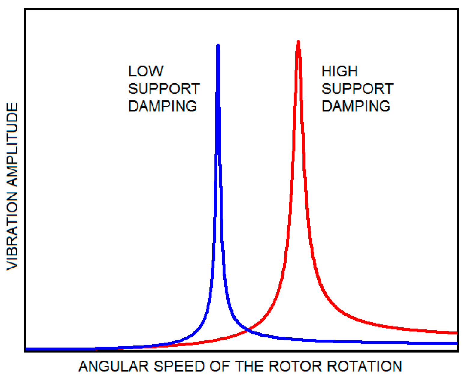
The second possibility is offered by controlling the damping effect in the rotor supports. Higher damping shifts the resonance peak to higher angular velocities, as evident from the frequency responses depicted in
Figure 1. To minimize the vibration amplitude of accelerating or decelerating rotors, damping in the support elements should be maximum for low velocities and as low as possible for higher angular speeds. Changing the damping at the moment when the angular velocity corresponds to the point of intersection of the frequency responses related to the low and high damping leads to the minimum vibration amplitude during running the rotor through the area of the critical speed.
The experience and analyses performed in the past show that sudden change in the damping effect induces a transient component of the rotor lateral vibration of large amplitude. This implies that the change in damping cannot be sudden, but it must be distributed in some time interval. The parameters that influence the magnitude of the rotor vibration in the resonance area are: (i) the moment of time when the change in the damping effect begins, (ii) the duration of the decrease/increase in the damping magnitude, (iii) the phase shift of the vibration at the time when the rotor passes the critical speed, and (iv) the rate of change in the rotor angular velocity.
The rate of acceleration or deceleration often depends either on the design of the rotating machine or on the requirements put on realization of the technological process. The value of the phase shift has a random character. Nevertheless, if the change in the speed starts at the point where the lateral displacement and velocity are the same as in the optimum case, the influence of this factor can be eliminated. The optimum values of the moment of starting and the period of duration of changing the damping effect can be determined by solving the optimization problem.
2.2. The Mathematical Model of a Squeeze Film Damper
The controllable damping in the rotor supports can be achieved by applying magnetorheological squeeze film dampers. The principle of their work is similar to the function of normal squeeze film dampers, only they are lubricated by magnetorheological oil, the properties of which are controlled by a magnetic field.
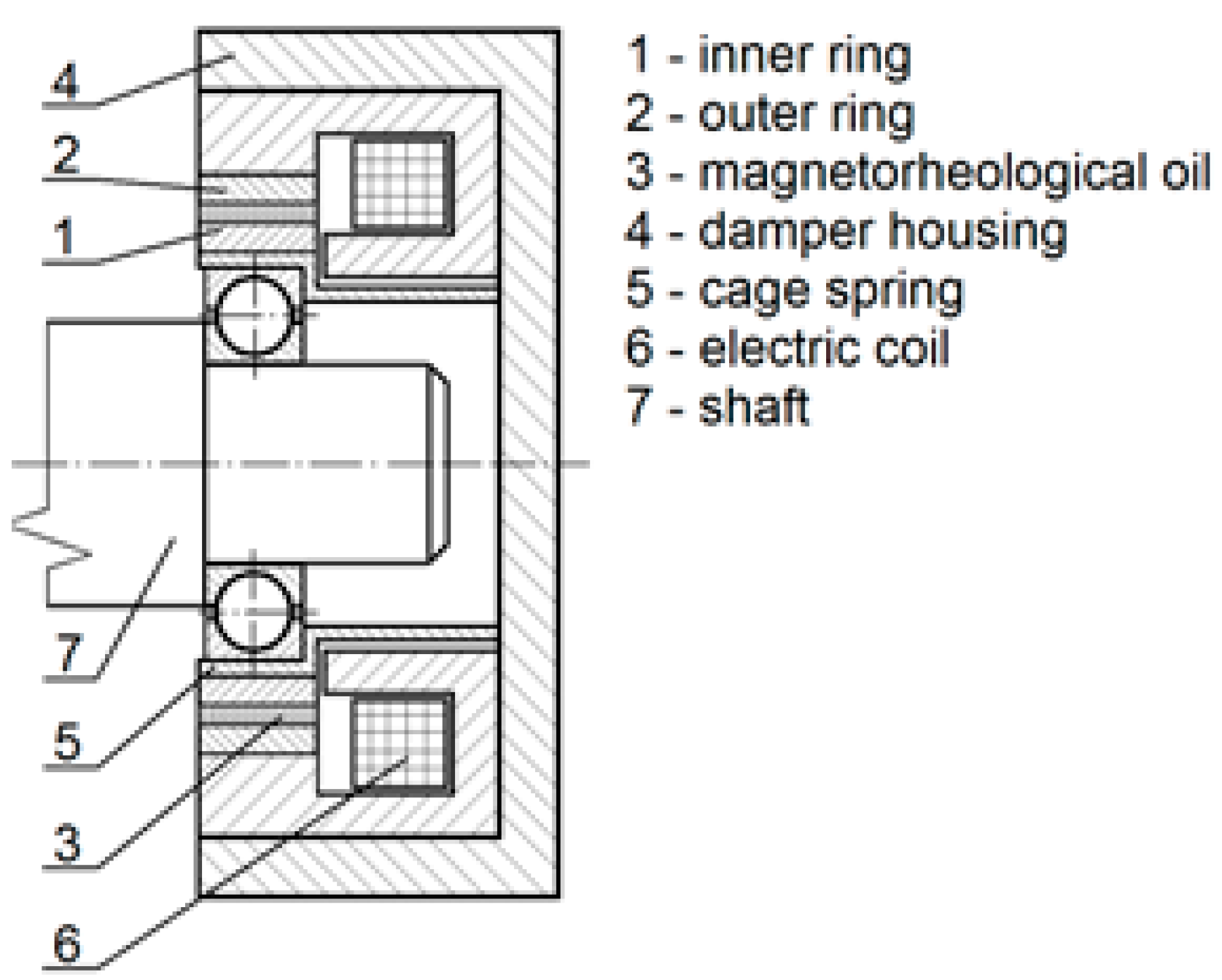
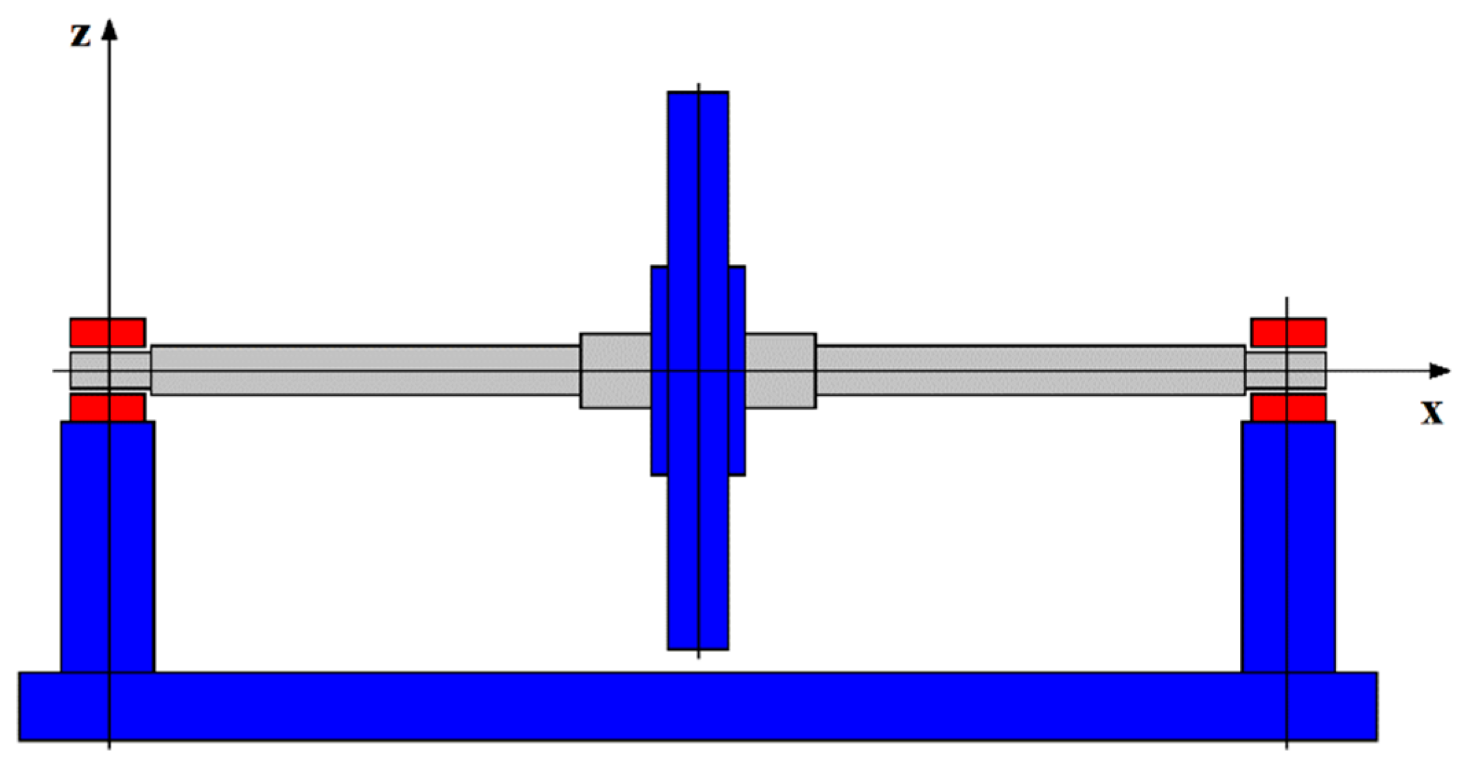
The radial magnetorheological damper (
Figure 2) is a controllable damping element used for vibration attenuation of rotors. The damper consists of an inner and outer ring. The latter is fixed to the stationary part. The rotor journal is supported by a rolling element bearing inserted in the inner damper ring, which is coupled with the damper housing by a cage spring of a cylindrical form. The narrow gap between the rings is filled with a thin layer of magnetorheological oil. The stationary part is equipped with an electric coil that generates magnetic flux, passing through the damper body, a thin layer of the magnetorheological oil, and the inner damper ring that returns to the coil.
The action of magnetic flux on the magnetorheological oil changes its character from a Newtonian-like liquid (no magnetic field) to a liquid with a yielding shear stress (presence of the magnetic field), the magnitude of which depends on magnetic induction of the magnetic field. In areas where the flow rate is low, the shear stress between two neighboring layers drops below the yielding shear stress and forms a core where the magnetorheological material behaves more similar to solid matter than liquid matter (But, the velocities of two neighboring layers are the same.). The velocity profile of the activated magnetorheological liquid flowing in a narrow gap or channel can be seen in
Figure 3. The core is formed in the middle of the flow. Squeezing the oil film between the inner and outer damper rings because of the rotor vibration and magnitude of the yielding shear stress are the most significant factors that influence the damping effect.
The developed mathematical model of the squeeze film damper is based on the classical theory of lubrication [
37,
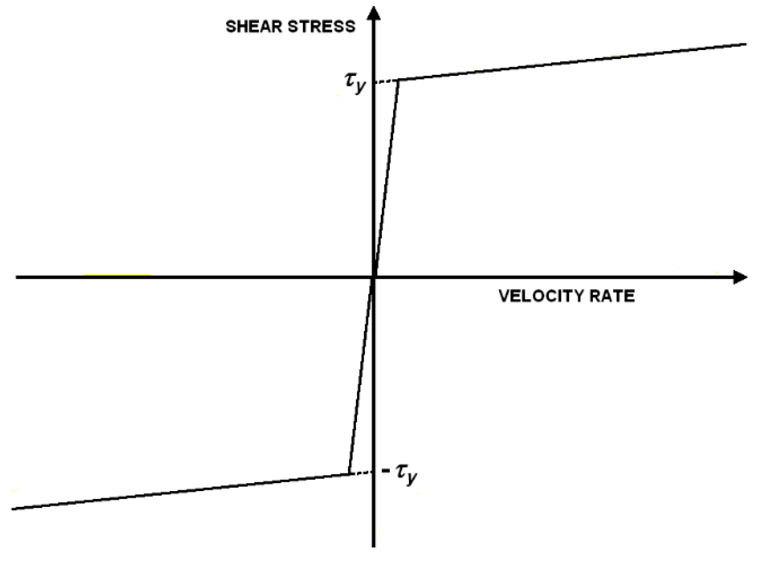
38], except the assumption for the lubricant. If the oil is not affected by a magnetic field, the lubricant is considered to be Newtonian liquid. If affected by a magnetic field, the oil is represented by bilinear (biviscous) material. Its flow curve is depicted in
Figure 4. In addition, it is assumed that the geometric and design parameters make it possible to consider the damper as short and symmetric relative to the damper middle plane, which is perpendicular to the damper axis. In the area where the width of the clearance between the rings rises because of the rotor vibration, the air is sucked in the damper from the neighborhood, and cavitation takes place there. Pressure in the cavitated regions is assumed to be constant and equal to the atmospheric one.
The pressure distribution in the full oil film is governed by the Reynolds equation, which is adapted to bilinear material and short dampers:
where;
p is the pressure in the magnetorheological oil film,
p’ stands for the pressure gradient in the axial direction,
η is the oil viscosity if not affected by a magnetic field,
ηC is viscosity in the oil core,
τy is the yielding shear stress,
τC is the shear stress at the core border,
h is the thickness of the magnetorheological fluid film [
37,
38], and
Z is the axial coordinate defining the position in the oil film. From the physical point of view,
ZC and
are the axial coordinate and the pressure gradient in the axial direction at the core border, respectively.
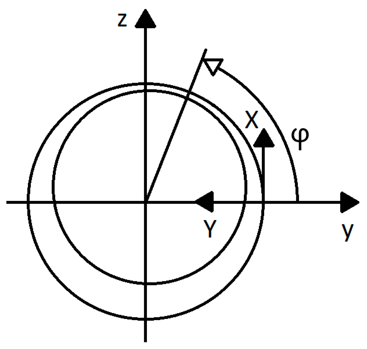
The governing equations are related to the coordinate system XYZ (
Figure 5). Equation (1) describes the pressure profile in the high flow rate area, while Equation (2) represents the same in the core.
More details on derivation and solution of Equations (1) and (2) can be found in [
22].
Components of the hydraulic force, by which the oil layer acts on the rotor journal, is calculated by integration of the pressure distribution around the circumference and along the length of the damper, considering different pressure profiles in the full oil film and cavitation areas.
Fmry,
Fmrz are the y (horizontal) and z (vertical) components of the magnetorheological hydraulic force acting on the rotor journal,
RD is the radius of the damper gap,
LD is the damper length, and
φ is the circumferential coordinate (
Figure 5).
Referring to Equation (2), the pressure in the full oil film depends on the yielding shear stress. Its magnitude can be approximated by a power function:
where;
B is the magnetic induction, and
ky and
ny are the proportional and exponential constants, respectively.
To determine magnetic induction of the magnetic flux generated by the electric coil in the damper gap, it is considered that the damper body consists of a set of meridian segments. Assuming that the magnetic reluctance is significant only in the gap between the rings and negligible in the ferromagnetic material of the damper housing, it holds for the magnetic induction in the damper clearance:
where;
kB is the design parameter,
μ0 is the vacuum permeability,
μMR is the relative permeability of the magnetorheological oil, and
I is the applied current in the coil.
The design parameter
kB depends on the number of the coil turns and efficiency of the transmission of the magnetic flux in the magnetic circuit. More details on its determination can be found in [
39].
4. Results
This chapter deals with optimization of parameters controlling damping in the rotor supports, with the aim to minimize the amplitude of the rotor vibration during its running through the regions of critical speeds. In addition, the applicability of the developed procedure is confirmed by means of computational simulations here. The chapter consists of two parts. The technical and operational data of the investigated rotor system are summarized in the first part. In the second part, the optimization procedure is introduced, and results of the conducted computational simulations are presented.
4.1. The Technical and Operation Parameters of the Simulated Rotor System
The technical and operation parameters of the analyzed rotor system are: 250 kg is the disc mass, 13 MN/m is the bending stiffness of the shaft, 8 MN/m is the stiffness of each cage spring, 10 Ns/m is the the coefficient of external damping, 0.00003 s is the viscous damping coefficient of the shaft material, 50 μm is the eccentricity of the disc center of gravity, 150 mm is the the damper gap diameter, 50 mm is the damper length, 1 mm is the width of the damper clearance, 0.1 Pas is the oil viscosity not affected by a magnetic field, 3000 Pas is the oil viscosity in the core, 20 kPa is the proportional constant of the yielding shear stress, 1.1 is the exponential constant of the yielding shear stress, 5.0 is the relative permeability of the magnetorheological oil, 60 is the damper design parameter, 150 rad/s is the angular speed of the rotor rotation before its acceleration, 250 rad/s is the angular speed of the rotor rotation after its acceleration, and 1.0 s is the period of the rotor acceleration.
4.2. Optimization of the Damping Effect Control Parameters
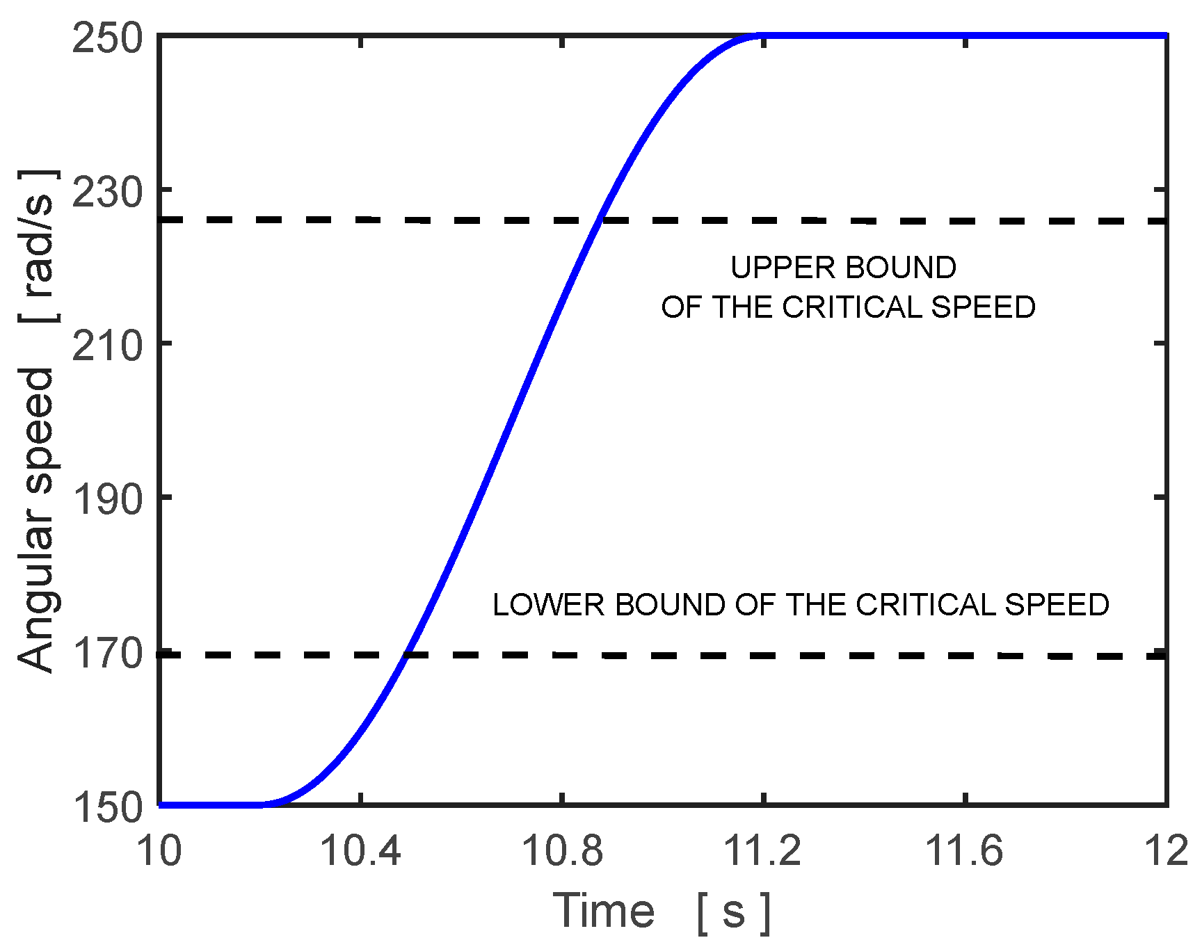
The time history of the rotor angular speed during the phase of its acceleration is defined by a sine function (
Figure 7).
It follows from the technical parameters that, if no damping is produced by the dampers (e.g., the dampers are not filled with the lubricating oil), the critical speed of the researched rotor is 169.4 rad/s. For the case when the dampers work in the overdamped regime, the critical speed rises to 228.0 rad/s. It implies that the rotor must pass through the area of critical speed during its running up.
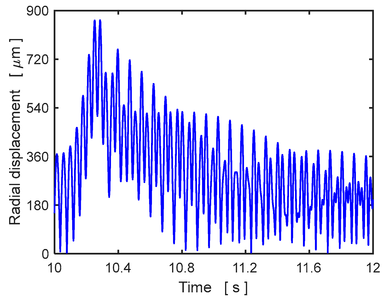
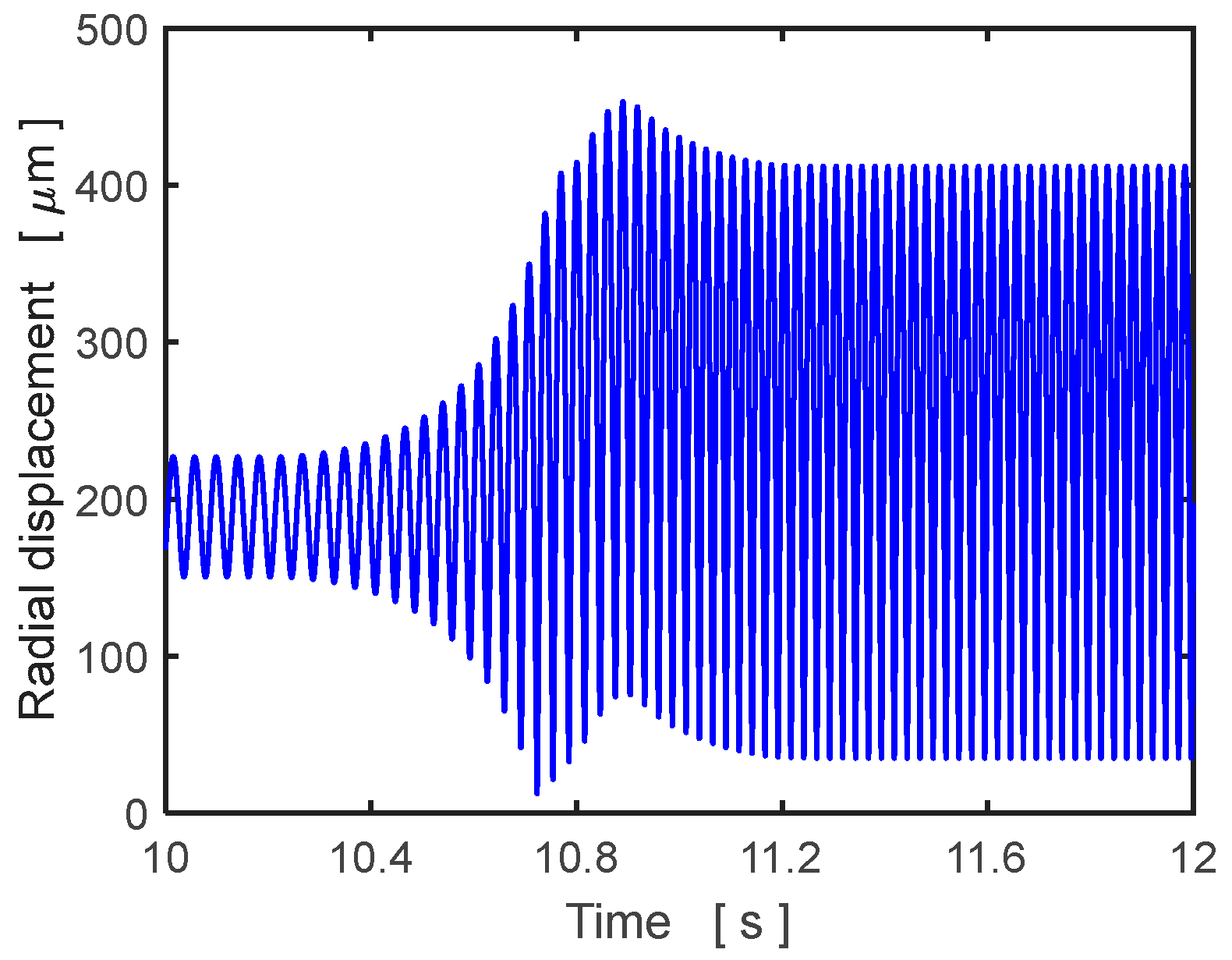
Figure 8 and
Figure 9 show the time histories of the radial displacements of the disc center during the rotor acceleration for two magnitudes of the control current, 0.0 A and 1.0 A. The phase shift of the excitation effect is 4/3 × π rad (240°). The maximum amplitudes are high, 864 and 453 μm, respectively.
As the frequency response curves depicted in
Figure 1 show, the initial high damping in the support elements must be changed to a minimum at just the right moment to minimize the oscillation amplitude. The reduction is achieved by switching off the applied current feeding the coils in the magnetorheological squeeze film dampers.
At the beginning, the rotor rotates at constant angular velocity of 150 rad/s, the coils of the dampers are fed by the current of 1.0 A, and the phase shift of the excitation effect is 4/3 × π rad (240°). At the point of time of 10.2 s, the rotor starts to accelerate. When the rotor reaches the speed of 195 rad/s, which corresponds to the moment of time of 10.67 s, the applied current is suddenly switched off.
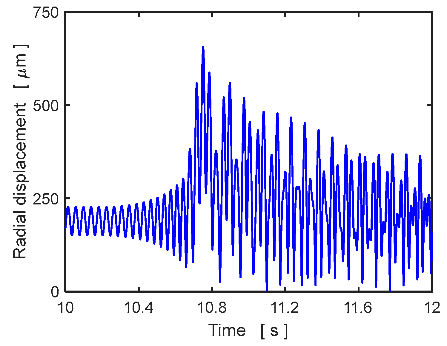
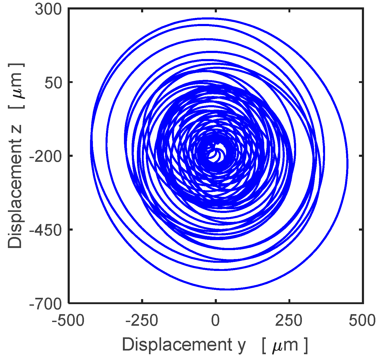
Figure 10 and
Figure 11 depict the rotor response, the time history of the disc center displacement in the radial direction, and its trajectory. The results show that, after switching, the current off excessive irregular oscillation of the rotor is induced.
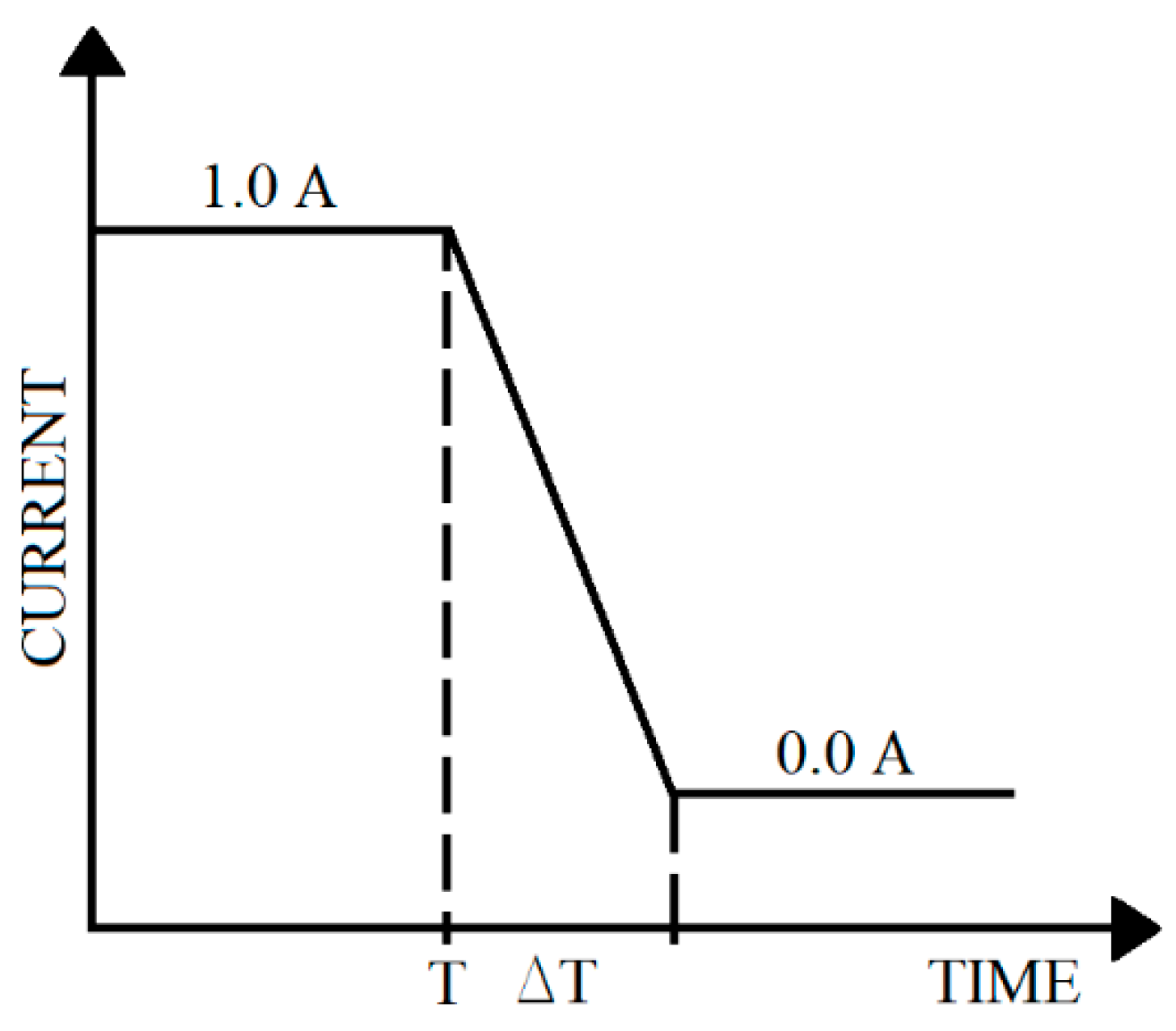
The results of the computational simulations supported by the theoretical pieces of knowledge and previous investigations show that, to reduce amplitude of the rotor oscillation during its running up, the current decrease must not be sudden, but it must be distributed in a certain time interval. Therefore, a linear drop in the current from 1.0 to 0.0 A was tested (
Figure 12).
T and Δ
T denote the moment of time of starting and the time of duration of the current decrease, respectively.
The optimum values of parameters of the current reduction (T, ΔT) are determined by solving an unconstrained optimization problem. The design variables are two—the time of the beginning of the current decrease (T) and the time of duration of this manipulation (ΔT). The objective function is implicit. It is introduced as a maximum lateral displacement of the disc center during rotor acceleration, and this value is determined by means of computational simulations.
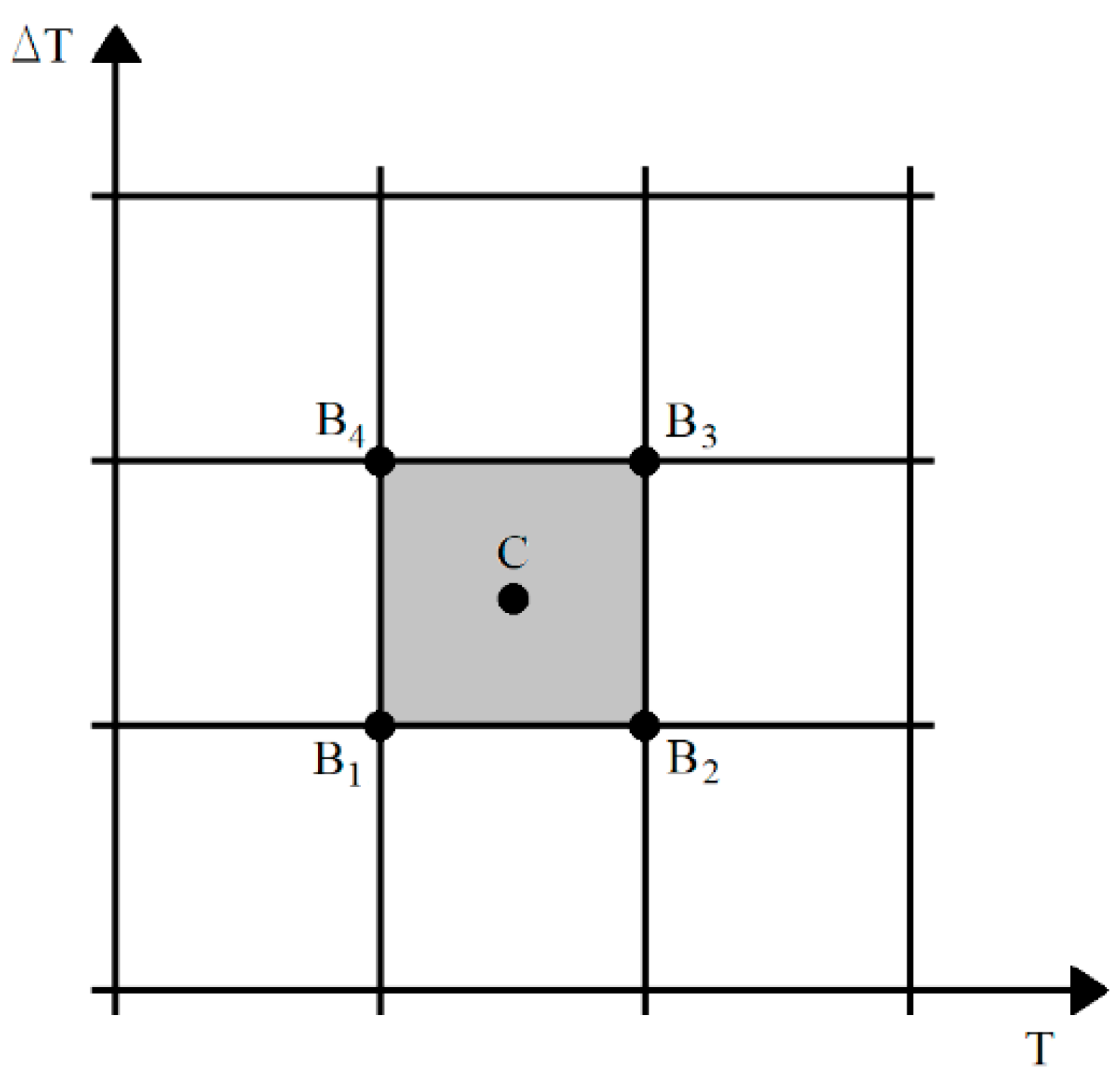
To solve the optimization problem, the iterative evolution optimization method was applied. This method requires us to determine the initial estimation of the optimum values of the design variables and specification of their increments. Consequently, the initial hypercuboid (a rectangular for the case of two design variables) is constructed, with the center point corresponding to the initial estimation of the optimum solution. The length of the hypercuboid edges is equal to the increments of the design variables. Then, the values of the objective function are determined at the center and each corner point of the hypercuboid. If the minimum value is referred to some corner, a new hypercuboid with the same length as the edges is constructed, with the center at this corner. If the minimum value of the objective function corresponds to the center, a new hypercuboid of reduced size (half the length of the edges) is constructed about this center. The same procedure is repeated in the next iterations. The iteration process is finished if the minimum value of the objective function lies at the center of the hypercuboid and the lengths of its edges are less than the accuracy, with which the solution is required to be obtained. More details on the evolution optimization method and its application can be found in [
41].
The notation of the center and the individual corners of the hypercuboid (rectangular for the case of two design variables) are depicted in
Figure 13.
The rotor starts to accelerate at the point of time of 10.20 s. The solution was performed for the phase shift of the excitation effect of 4/3 × π rad (240°). The initial values of the optimum solution were estimated, and the beginning (
T) and duration (Δ
T) of the current decrease by 10.7 s and 0.4 s, respectively. The time increment was chosen 0.4 s, which is the same for both design variables. The iteration process is summarized in
Table 1.
R stands for the objective function value (maximum lateral displacement of the disc center).
After performing six iteration steps, the computational procedure gives the optimum values: the time of beginning of the current decrease 10.50 s and the time of duration of this manipulation 0.60 s. As it is easier to measure the angular speed than the time, the beginning of the current decrease corresponds to the angular velocity of 170.2 rad/s.
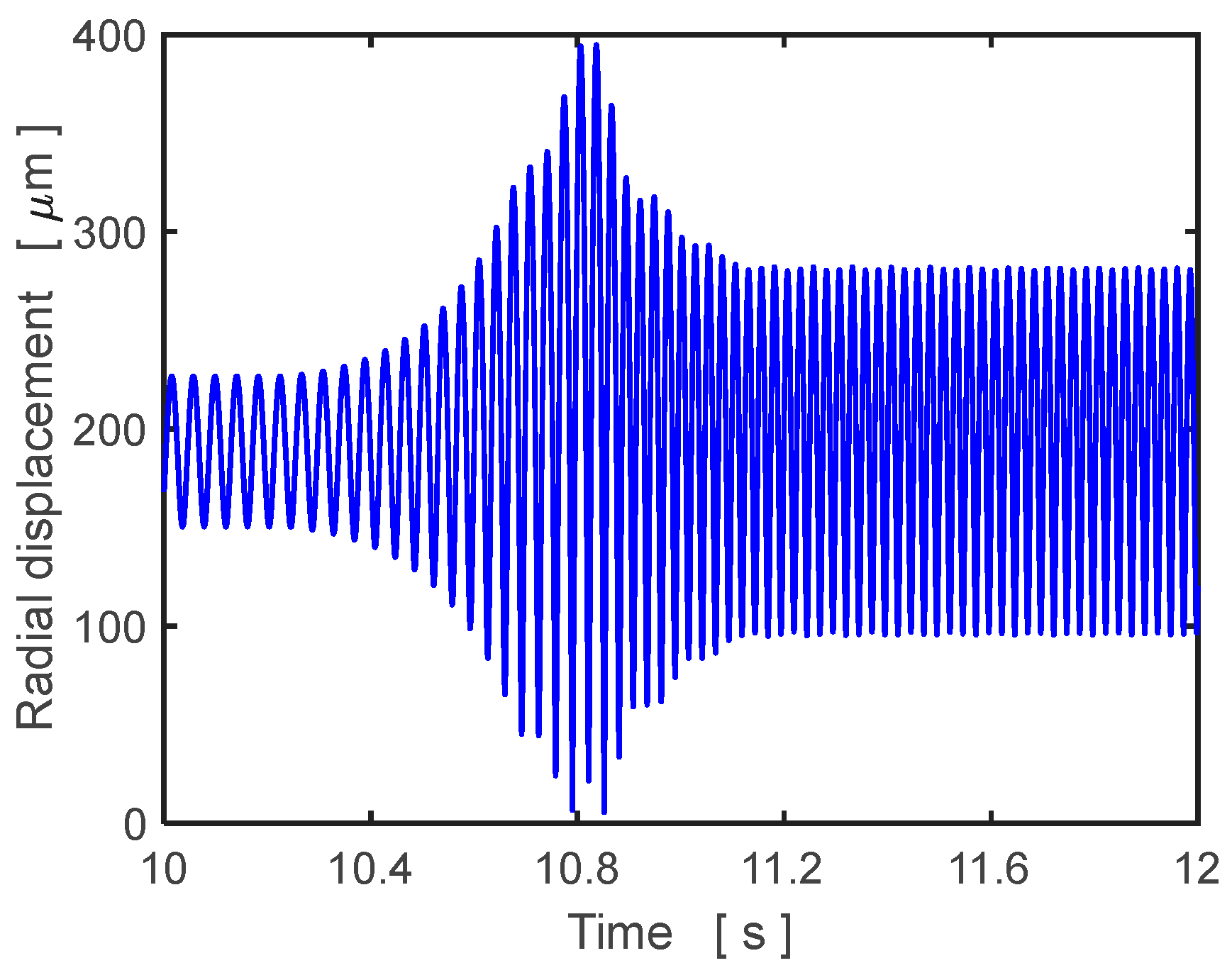
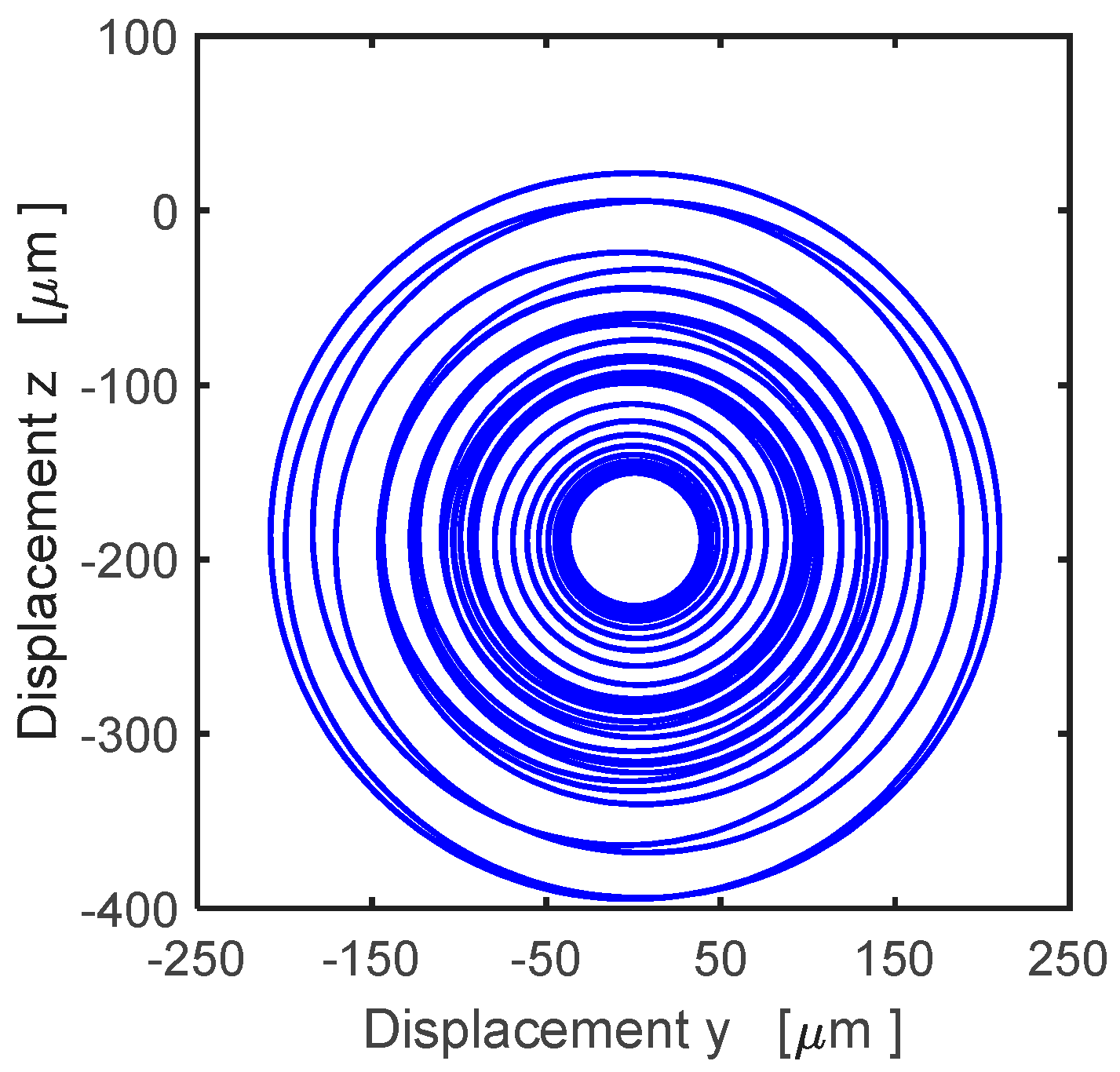
The system response on the optimized decrease in the damping effect is depicted in
Figure 14 and
Figure 15.
Figure 14 shows the time history of the radial displacement of the disc center, and
Figure 15 shows the disc center trajectory. The maximum value of the radial displacement reads 395 μm.
The same method was applied for calculation of the optimum values of the control parameters related to the current decrease for several different values of the phase shift
ψ of the excitation effect. The results are summarized in
Table 2.
Even if the differences in the maximum amplitude of the disc vibration are very small, it is evident that the phase shift of the excitation effect induced by the disc unbalance has influence on efficiency of the control process.
If adequate means of measurements are to be used, it is possible to choose the case (reference case) when the optimum vibration amplitude is minimum and to find the displacements and velocities of the disc vibration (reference kinematic parameters) at the moment when the rotor starts to accelerate and the angular speed (reference angular speed) at the moment when the current decrease begins. Then, in a general case for arbitrary value of the phase shift, if (i) the acceleration starts at the moment when the rotor kinematic parameters (displacements and velocities) are equal to the reference ones, (ii) the current decrease begins when the rotor angular velocity reaches the reference value, and (iii) duration of the current decrease is the same as in the reference case, then the magnitude of the maximum radial displacement of the disc center will be optimal and the same as in the reference case.
Figure 16 shows the time histories of displacements of the disc center in the horizontal and vertical directions referred to the case (reference case) when the maximum vibration amplitude of 394 μm is minimum from all investigated cases (
Table 2). The corresponding phase shift of the excitation effect is 5/3 × π rad (300°). The reference values of the displacements in the horizontal and vertical directions, the reference value of the angular speed of the rotor rotation, and duration of the current decrease are −19.11 μm, −156.09 μm, 170.2 rad/s, and 0.6375 s, respectively.
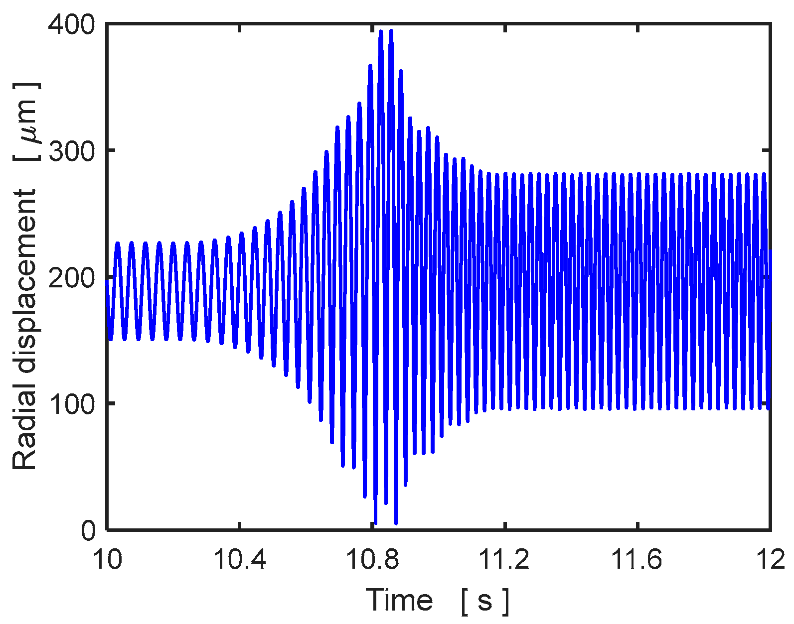
The same analysis was performed for the arbitrary chosen phase shift of 1/2 × π rad (90°). The rotor acceleration started at the point of time of 10.225 s, when the horizontal and vertical displacements of the disc center were equal to the reference values (−19.11 and −156.09 μm, respectively). The current decrease started at the point of time of 10.4875 s, when the angular speed of the rotor rotation reached the reference value of 170.2 rad/s and lasted for the reference period of 0.6375 s. The resulting time history of the radial displacement of the disc is depicted in
Figure 17. The maximum displacement is 394 μm, which corresponds very well to the maximum radial displacement of the operation regime with the phase shift of the excitation effect of 5/3 × π rad (300°).
It is evident from comparing
Figure 8 and
Figure 9 with
Figure 17 that the control of the damping effect in the rotor supports significantly reduces amplitude of the disc oscillation. Comparison of the simulation results with the phase shift of 5/3 × π rad (300°) and arbitrary chosen 1/2 × π rad (90°) shows that the maximum values of the time histories of the radial disc displacement are the same.


