Optimizing Induction Heating of WNiCo Billets Processed via Intensive Plastic Deformation
by
Lenka Kunčická
1,*, 
Adéla Macháčková
2,*,
Rudolf Petrmichl
2,*,
Zuzana Klečková
2 and
Martin Marek
3 1
Institute of Physics of Materials, CAS, 61662 Brno, Czech Republic
2
Faculty of Materials Science and Technology, VŠB—Technical University of Ostrava, 70833 Ostrava 8, Czech Republic
3
IT4innovations—National Supercomputing Centre, VŠB-TU Ostrava, Studentská 6231/1B, 70800 Ostrava-Poruba, Czech Republic
*
Authors to whom correspondence should be addressed.
Appl. Sci. 2020, 10(22), 8125; https://doi.org/10.3390/app10228125
Submission received: 26 October 2020
/
Revised: 10 November 2020
/
Accepted: 12 November 2020
/
Published: 17 November 2020
Abstract
:Featured Application
The study documents that, although being a challenging paramagnetic material, pre-sintered WNiCo pseudoalloys can be (industrially) processed into billets featuring high surface quality using an optimized combination of induction heating and consequent deformation processing, herein provided via the rotary swaging method.
Abstract
The aim of the work is to optimize the induction heating regime and propose a suitable deformation temperature for a pre-sintered powder-based tungsten heavy alloy workpiece subsequently processed via rotary swaging. The heating regime is designed with the help of numerical analyses and subsequent experiments. The first part of the study focuses on the theoretic background of the induction heating and comprises the development of a reliable induction heating model via performing electromagnetic simulations in two individual computational software packages (for verification). The second part of the study then involves the optimization of the heating regime using the designed numerical model. Last but not least, the predicted results are compared to the experimentally acquired results, and the optimized heating regime, applicable before experimental rotary swaging of the WNiCo workpiece, is proposed. The results of the microstructure analyses of the workpiece heated to the selected optimum deformation temperature of 900 °C showed that the designed induction heating procedure provided sufficient heating of the bulk of the workpiece (contrary to the lower swaging temperature), as the swaged microstructure featured well-deformed tungsten agglomerates. Furthermore, the analyses documented the high-quality oxidation-free surface of the particular workpiece (contrary to the higher swaging temperature).
1. Introduction
Within the last five decades, induction heating has become a favorable method for the heating of metallic workpieces throughout various industrial branches (e.g., transportation, aerospace, marine industry, etc.) [1]. It is mostly used to (pre)heat ferromagnetic materials, such as steel [2], since they intensify the magnetic field and thus induce the induction effect already at relatively low frequencies. However, the selection of the particular frequency depends on the geometry of the workpiece and its material properties, since both the electric conductivity and magnetic permeability can be (highly) temperature-dependent. Nevertheless, induction heating is also preferred for other applications, such as the melting of metals [3], the annealing and quenching of metallic components and surfaces [4], the preheating of workpieces intended for subsequent deformation processing [5], surface heating prior to specific surface treatments [6], and more. Under optimized conditions, induction heating can be precisely controlled to enable accurate gradual heating at relatively low costs. On the other hand, unsuitable settings of the heating process result in insufficient and/or inhomogeneous heating of the workpiece, and increase the possibility of the occurrence of microstructure inhomogeneities and defects within the material (e.g., local melting or overheating resulting in undesired abnormal grain growth), as well as the development of an unfavorable stress state, which can result in the occurrence of residual stress during subsequent processing [7,8,9].
The design of induction heating processes in the industry should be performed considering the technological, as well as metallurgical, viewpoints, especially for materials prepared via specific technological procedures, such as via powder metallurgy. Such specific materials should be processed with the highest care, since unnecessary increases in the heating time can non-negligibly affect their structures, as well as provoke surface oxidation [10]. The oxidation of workpieces during heating, which can hardly be avoided in industrial conditions, is an important issue in general. Increasing the heating time significantly affects not only the structures, but also the level of surface oxidation of the workpieces. While the level of surface oxidation can more or less be affected via the modification of furnace atmosphere or the usage of protective coatings during heating in conventional furnaces [11], possible structure changes are usually complex and their control is complicated (for example, the grains grow exponentially with increasing heating time [7]). The application of a rapid induction heating is thus very favorable, not only for challenging materials.
The optimization of the induction heating process can be advantageously performed with the help of numerical modeling. Others have presented numerous models applicable for induction heating in specific cases. For example, Bay et al. [12] developed numerical and mathematical models of induction heating for several specific inductor geometries, Liu et al. [13] proposed a numerical method to predict the temperature field of induction heating and investigated the distribution of temperature, and Riccio et al. [14] compared different numerical models and performed electromagnetic analyses of the bonding of reinforced polymer components with induction heating. Some authors even proposed the induction heating process as a supportive method to fabricate long tubular parts from tungsten heavy alloys (THAs) [15]. Nevertheless, studies focusing on the induction heating of THAs intended to be plastically deformed after heating are scarce, possibly primarily due to the paramagnetic behavior of these materials. Despite the fact that their pre-process heating via induction is a challenge, the usage of paramagnetic materials in the industrial and commercial spheres is on the rise.
THAs feature exceptional mechanical and physical properties, among which are, e.g., high density (17–19 g/cm3) and high strength (up to 1900 MPa after optimized deformation processing) [16,17]. They are typically used for radiation shielding, as therapeutic devices in oncology, or as kinetic energy penetrators [8,18]. THAs are usually fabricated via methods of powder metallurgy [19]. The mixed powders are isostatically pressed under a protective atmosphere (H2, Ar2, vacuum) and sintered within the temperature range from 1000 °C to 1550 °C [16,20]. The powder mixture typically consists of more than 90 wt. % of tungsten plus a mixture of other elements with lower melting temperatures (Ni, Co, Fe). Within the mixtures, the grain boundaries of the elements featuring lower melting temperatures locally melt during sintering, and consequently form a matrix binding the agglomerated tungsten particles together [18,21]. The alloying elements thus provide the plasticity of the final material, whereas tungsten primarily increases the ultimate tensile strength (UTS).
Based on the aforementioned, the optimum combination of strength/plasticity for THAs can be achieved by optimizing the chemical composition and sintering conditions. Nevertheless, the deformation processing performed after sintering can also non-negligibly affect the performance of the final product [16,22]. Intensive deformation processing contributing to the structure refinement and enhancement of the final properties can advantageously be performed via the severe plastic deformation (SPD) methods [23], such as equal channel angular pressing (ECAP) [24,25,26], twist channel (multi) angular pressing (TCAP, TCMAP) [27,28], ECAP with (partial) back pressure (ECAP-BP, ECAP-PBP) [29,30], high pressure torsion (HPT) [31,32], etc. These processes are discontinuous and can only be used to process samples of limited dimensions. On the other hand, continuous methods of intensive plastic deformation, such as ECAP-Conform [33], accumulative roll bonding (ARB) [34] or rotary swaging (RS) [35], can be used to process long axisymmetric workpieces and, moreover, are industrially applicable. RS is used to gradually reduce the cross-sections of workpieces and increase their lengths via the repeated action of the swaging dies [36]. It induces changes in the shapes and dimensions of the workpieces, and is thus favorable for the production of final products featuring the required shapes. RS can be performed under cold, warm, and hot conditions to process various materials, including challenging ones, such as powder-based alloys, laminated materials, biomaterials, or composites [37,38,39,40,41].
The aim of the study is to design an optimized induction process applicable in the process of the manufacturing of high-quality billets from pre-sintered WNiCo pseudoalloys consisting of a consequent combination of induction heating and rotary swaging. The first part of the study focuses on the characterization of the induction heating process, including a brief description of the electromagnetic parameters within the inductor and workpiece, and the design of the optimum induction heating model. For these purposes, numerical modeling using two individual 2D and 3D software packages was performed. The second part of the study then deals with the 3D numerical analysis performed with the aim of proposing suitable induction heating parameters and a deformation temperature for rotary swaging of the particular WNiCo alloy. Finally, the experimental realization of the induction heating and subsequent warm rotary swaging of the sintered workpieces is performed and the experimental results are discussed together with the predicted ones.
2. Induction Heating and Numerical Simulations
2.1. Induction Heating–Basic Principles
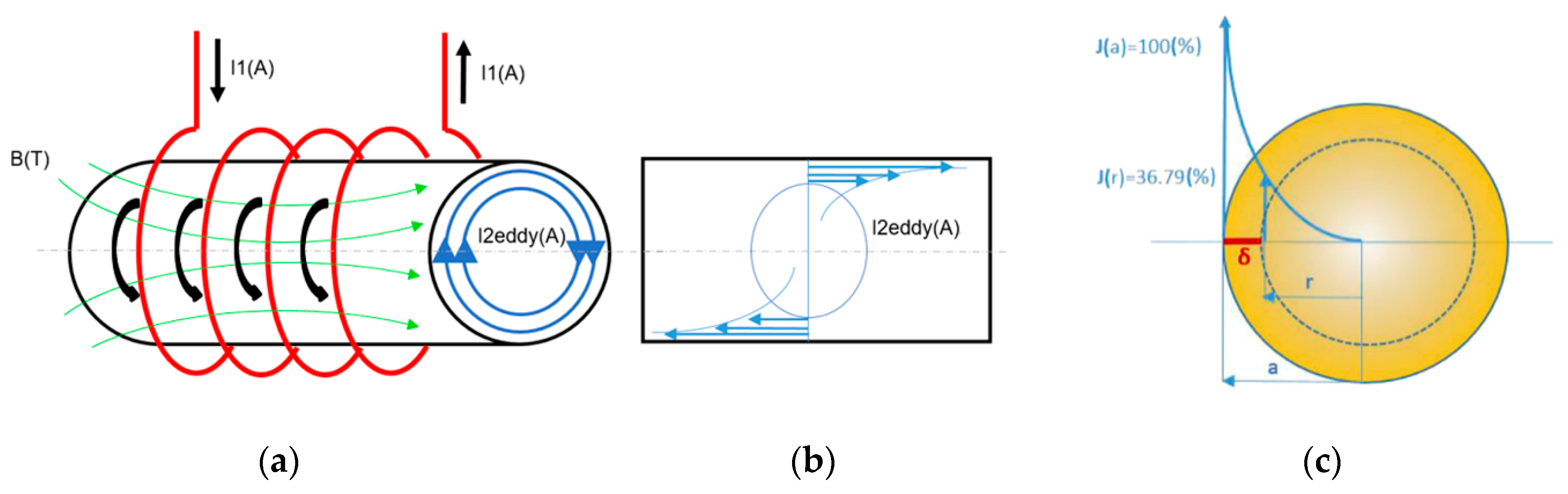
The basic principle of induction heating lies in affecting the heated workpiece by a rapidly alternating magnetic field, which is typically generated by an inductor coil (depicted in red color in Figure 1a) surrounding the heated workpiece. The alternating electric current I1 (typically generated by a frequency converter) of the required amplitude and frequency, depicted in the black color in Figure 1a, is supplied through the coil. The heating process is then realized by the induction principle: the rapidly alternating magnetic field in the workpiece generates the induced voltage within the workpiece [42,43]. In other words, an induction field, variable in time, induces a local electromagnetic force resulting in the generation of voltage. This induced voltage, enclosed by the workpiece cutting plane, generates a short circuit immediately generating eddy current I2. The eddy current is shown in Figure 1a,b, demonstrated as I2eddy (A) (the direction of which is depicted in blue color in Figure 1a), and eventually results in the heating of the workpiece via the Joule heating principle, i.e., the eddy currents are intensified by the developed short circuit.
Generally, the distribution of the induced eddy current is not uniform throughout the cross-section of the heated workpiece; its intensity is the highest in the surface region of the workpiece and decreases rapidly towards its axial region (see Figure 1b). This phenomenon is characterized as the skin effect, which is defined by the penetration depth δ (m) expressed via Equation (1),
where f is the working frequency of the electromagnetic field (Hz), σ is electric conductivity (Ω−1.m−1), and µ is magnetic permeability (H.m−1).
In other words, Equation (1) determines the current density beneath the workpiece surface, which is equal to 36.79% of the current density value on the surface. This value is the boundary value of the conductive layer’s thickness; below this boundary (i.e., further towards the workpiece axis) the effect of the current density decreases significantly. From Equation (1) it is also evident that the mutual relations of the individual affecting parameters are the primary factors influencing the induction heating process. The parameters that can be varied using Equation (1) are, for example, the penetration depth at a given frequency, or the particular temperature distribution throughout the workpiece cross-section.
2.2. Analytical Solution
For geometrically simple symmetrical inductors and workpieces, calculations of the distributions of magnetic field, eddy currents and heat sources can be performed analytically. However, prior to such an analytical solution, numerous simplifications have to be introduced. The equations applied to characterize the distributions of the investigated parameters are in this case calculated using the Bessel functions, the solution of which is rather complicated and can lead to results of insufficient reliability for complicated tasks [44]. For this reason, the characterization and numerical expression of the parameters affecting the workpiece and its vicinity during the induction heating process are based on the general equations for the characterization of the magnetic field—the Maxwell equations (see, e.g., [45]).
The Maxwell equations are then supplemented with equations characterizing the heated material (Equations (2)–(4)),
where B is magnetic induction (T), E is the electric field intensity (V·m−1), D is electric induction (C·m−2), ε is electric permittivity (F·m−1), H is magnetic field intensity (A·m−1), and J is current density (A·m−2).
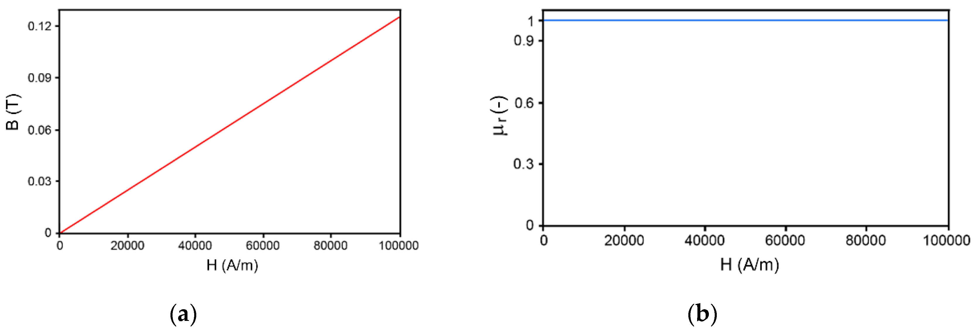
The fact that especially the σ and µ parameters influence the behavior of the heated metal in the outer alternating magnetic field needs to be pointed out. For the induction heating of ferromagnetic materials featuring high µr values (hundreds to thousands), the magnetization process is non-linear. Such materials intensify the magnetic field, and thus the induction effect generating the eddy currents is already substantial at low frequencies. The design and analyses of induction heating are typically based on amplitude magnetizing characteristics. Nevertheless, both these characteristics are strongly temperature-dependent up to the Curie temperature, at which ferromagnetism diminishes. Beyond this critical temperature, the material, including a ferromagnetic one, further behaves as paramagnetic. Crossing this critical temperature also results in the modification of the characteristic hysteresis loop. In other words, the non-linear dependence changes into linear and magnetic permeability are further expressed by a constant value approaching the limit of 1. However, this does not apply for paramagnetic materials [46]. Tungsten heavy alloys (THA), being paramagnetic, feature the permeability value of 1, i.e., their B/H characteristics are linear; see Figure 2a (to be able to thoroughly characterize the magnetic properties of THAs, the magnetic susceptibility, ~7.8 × 10⁻⁵ for THAs, would also have to be considered). Similarly, µr is also constant, expressed by the value of 1, for this material (see Figure 2b).
2.3. Numerical Solution
For the reliable modeling of the induction heating process, the finite element method (FEM) working with real geometrical models of inductors and workpieces can advantageously be applied. The computational algorithm and methodological procedure can significantly differ according to the used computational software. In the presented study, we used two different pieces of software, FORGE NxT and ANSYS-Maxwell, to design the induction heating procedure with the highest accuracy possible.
Forge NxT is a specialized computational software by Transvalor s.a. designed primarily to enable simulations of forming processes under cold, warm, and hot conditions. However, it is also suitable for the solving of issues related to thermomechanical processing and heat treatments. For this reason, an efficient electromagnetic module, which can favorably be applied for simulations of induction heating, is integrated within the software [46,47,48,49]. The numerical simulation of the electromagnetic induction process, including simulating the generated eddy currents, using the Forge NxT software is based on the method of finite elements, i.e., Nedelec elements. The software combines the Maxwell equations with the above-presented materials equations (Equations (2)–(4)), and implements further equations characterizing the conditions in boundary regions—Neumann and Dirichlet boundary conditions. The fact that the µ and σ parameters can be defined as temperature-dependent needs to be taken into account. Furthermore, magnetic permeability can be defined depending on magnetic field intensity. Finally, the numerical simulation of induction heating using the Forge NxT software processes in a loop comprising an electromagnetic simulation followed by a thermal simulation [50,51,52].
ANSYS-Maxwell is a specialized software package designed for calculating low-frequency electromagnetic fields in 2D and 3D spaces. The main advantage of this software is the possibility to use an automatic adaptive mesher for static and harmonic tasks. The principle of the software lies in implementing the Maxwell equations, together with FEM. The Maxwell equations are solved depending on the particular calculated issue—electrostatics, magnetostatics, eddy currents, or transient electromagnetic issues. For the presented study, we used the 2D axisymmetric model and eddy currents solver, which is suitable for solving steady-state types of issues, as well as alternating the sinusoidal magnetic field (AC) in the frequency zone. Materials with linear, as well as non-linear, magnetization characteristics can be calculated; this software package is thus advantageous for various geometric configurations of inductor coils and magnetic circuits, from electromagnets, through various types of engines, to induction heating [46].
2.4. Finite Element Modeling
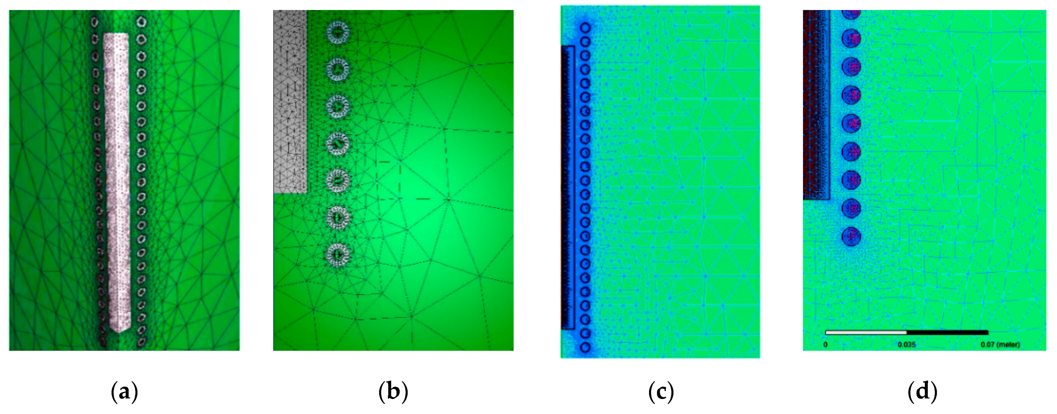
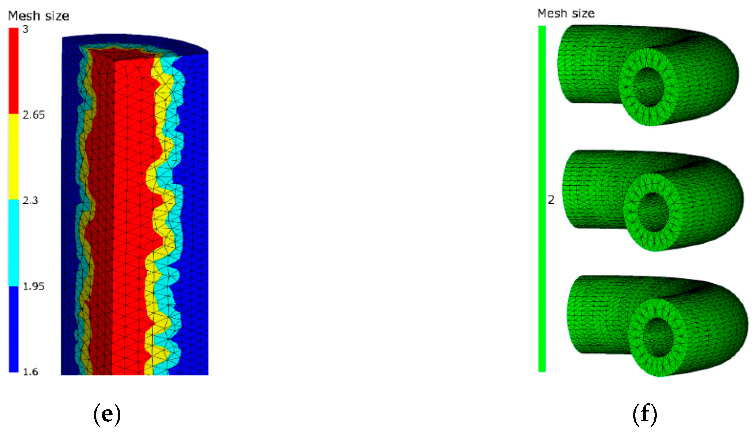
The numerically simulated induction heating involved an induction coil with 23 windings and a working frequency of 15 kHz, which was implemented in both the models. The relatively high number of windings was selected based on the relatively high workpiece length (approximately 330 mm). The geometrical dimensions and material parameters were identical for both the simulations, although the FEM computational methods differed. The input boundary conditions used for the simulation were the following: modulus of elasticity = 125.45 MPa; thermal conductivity = 174 KJ/ms °C; Poisson’s ratio = 0.337; density = 19.3 g/cm−3; specific heat = 0.75 KJ/t °C; and linear expansion coefficient = 1.88 K−1. To optimise the heating process, three individual target heating temperatures were investigated in three individual simulations. These final deformation temperatures were 700 °C, 900 °C and 1100 °C. The electric current defined in the three simulations was I = 70, 90, and 120 A, respectively. The heated WNiCo workpiece was defined by the following material parameters, acquired based on experimental stress–strain testing at an elevated temperature: ultimate tensile strength = 1067 MPa; elongation to failure = 21.7%. In both the 2D and 3D predictions, the geometry of the coil was determined by the number of windings. Meshing of the investigated area was performed in accordance with the required calculation accuracy. The meshes were optimized according to the Global mesh model (3D space for magnetic field computations) in both the simulations in order to maintain reasonable computational times. For this reason, we used anisotropic meshes featuring the finest elements within the workpiece and its closest vicinity (see Figure 3a,b for the generated mesh and the details, respectively, of the 3D model, Figure 3c,d for the generated mesh and the detail, respectively, of the 2D model, and Figure 3e,f for the details of the 3D models of the heated workpiece and inductor coil, respectively). In the 3D model, the inductor consisted of 29,878 elements in total, whereas the workpiece consisted of 39,351 elements in total. The total global mesh of the 1/24 symmetry part contained 273,975 elements in total. The electromagnetic characteristics and heat transfer parameters were investigated for a pre-sintered WNiCo workpiece with the diameter of 25 mm and length of 330 mm. The analyzed material exhibits a paramagnetic behavior, which means that the permeability in the calculations was set to the value of 1 (µr = 1).
2.5. Comparison of Electromagnetic Tasks in 2D and 3D
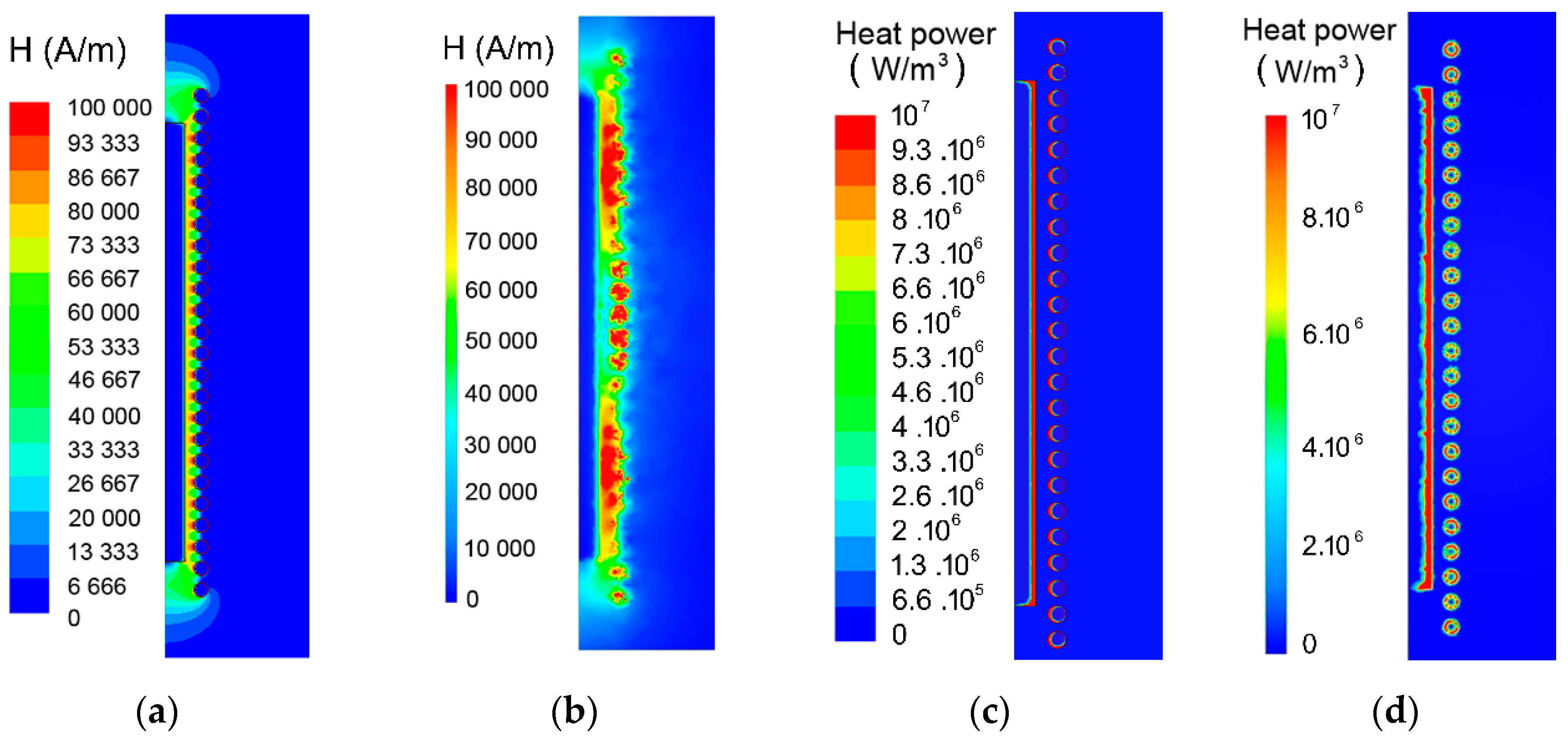
Before continuing with the thermal analyses of induction heating of the investigated WNiCo workpieces, the optimization of the designed 3D model was performed via mutual comparison of the results of 2D and 3D electromagnetic parameter calculations. The comparison of the predictions performed using both the pieces of numerical software showed sufficient correlation; despite the fact that the Forge NxT software computations were performed in 3D and the ANSYS-Maxwel computations were done in 2D, the results exhibited only minor deviations. Both the simulations of magnetic field intensity exhibited a homogeneous distribution of this parameter along the workpiece (see Figure 4a,b for magnetic field intensity distributions according to the 2D and 3D models (cutting plane), respectively). However, its distribution showed certain inhomogeneity and a greater occurrence of the maximum values in the 3D model (Figure 4b). The distribution of magnetic induction was comparable to the distribution of magnetic field intensity in both the models (not shown here). Both the magnetic parameters also non-negligibly affected the distribution of current density. The only visible difference revealed by the comparison of both the models was in the skin effect, which appeared to be approx. 30% greater in the 2D model. However, this difference can primarily be attributed to different mesh densities. The last investigated parameter was the Joule heat, i.e., heat power, the distribution of which exhibited a character similar to the distribution of current density in both the models (see Figure 4c,d for heat power distributions according to the 2D and 3D (cutting plane) models, respectively). In the 3D model (Figure 4d), however, the heat penetration depth was greater and its distribution along the workpiece was less homogeneous than in the 2D model (Figure 4c).
3. Material and Methods
The experimental processing of the induction heating/warm swaging procedure and the verification of its industrial applicability was a non-negligible part of this study. Schematics of the swaging process, including the initial workpiece, induction heating, swaging, and final swaged piece, are depicted in Figure 5a, whereas the assembly of the real experimental industrially applicable procedure of THAs formation, including the inductor coil, heated workpiece, and swaging head, is depicted in Figure 5b.
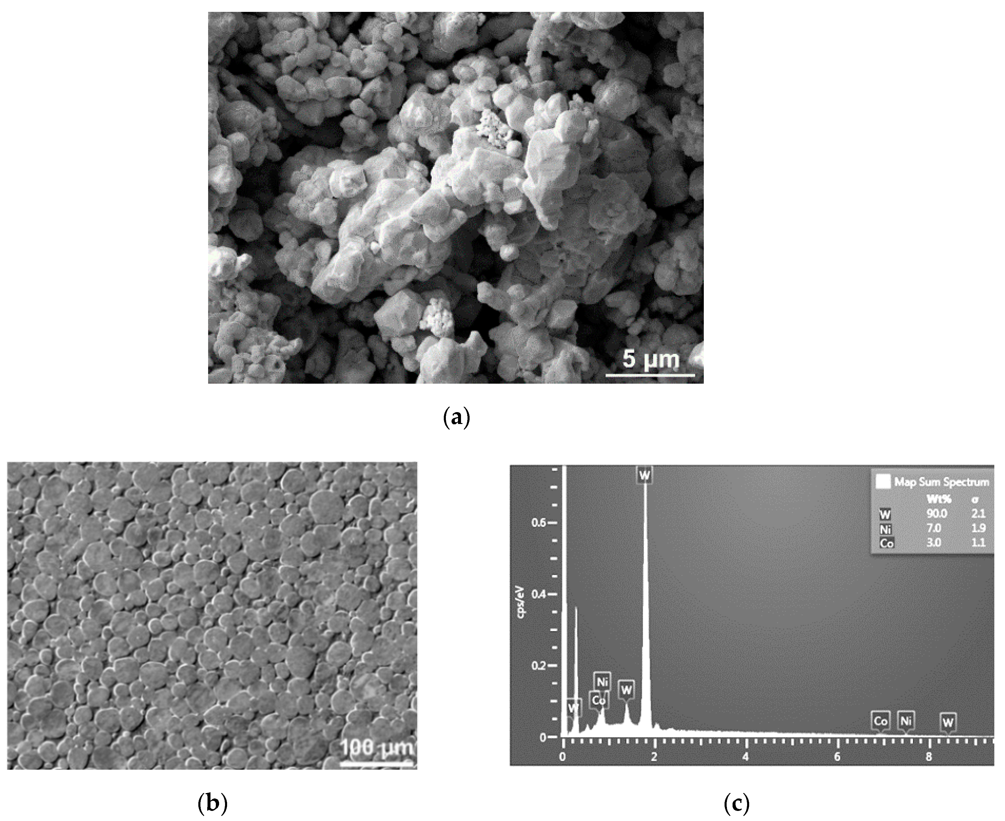
Experimental verifications of the predicted results were performed with 90W7Ni3Co workpieces prepared by the ÚJP Praha a.s. (Prague, Czech Republic) company from a homogeneous mixture of W, Ni, and Co elemental powders, with a minor portion of impurities < 13 ppm (Fe, Cr, Al, Mo, Ca), by mechanical alloying. The sizes of the powder particles within the final mixture varied between 2 and 4 µm, and the mean particle size was 2.78 μm (Figure 6a). Having mixed the powders, the mixture was consolidated into individual workpieces by CIP (cold isostatic pressing) at 400 MPa, sintered at the temperature of 1525 °C for 20 min under a protective atmosphere (hydrogen), and eventually cooled down naturally (in furnace). The chemical composition of the sintered pieces was analyzed using a map scan via the SEM-EDX method. In other words, the powder ratios calculated before mixing the powders were verified after sintering via the EDX analysis. The measured area and corresponding acquired spectrum are depicted in Figure 6b,c, respectively. The individual sintered pieces with the approximate length of 330 mm and diameter of 25 mm were subsequently heated to the selected deformation temperatures of 700 °C, 900 °C, and 1100 °C. The maximum heating time given by the industrial requirements was 140 s, whereas the particular deformation temperatures were selected based on our previous experimental studies dealing with the heating of THA workpieces in a conventional electric furnace (e.g., [16,18]). Temperature control during heating was performed by an optical pyrometer (surface temperature), and verified via implementing two individual K-type thermocouples—one at the surface, and another in the axial region of the workpiece (inserted in an opening pre-drilled via water jet). After pre-heating, the workpieces were swaged to the final diameters of 20 mm. The lengths of the final swaged pieces were approximately 400 mm.
The microstructure analyses were performed on cross-sectional cuts of the sintered and swaged pieces. The samples were mechanically ground, mechanically polished using the Eposil F substance (Metalco Testing, Prague, Czech Republic), and finally polished using a colloidal silica suspension (VibroMet 2 Vibratory Polisher, Buehler, Esslingen, Germany). Scanning electron microscopy (SEM) analyses (both SEM-EDX and SEM-EBSD) were performed using a Tescan Lyra 3 microscope (Tescan Brno s.r.o, Brno, Czech Republic). The surface quality of the swaged piece was investigated using the innovative 4K digital optical microscopy via the KEYENCE VHX7000 equipment (Keyence International, Mechelen, Belgium).
4. Results
4.1. Induction Heating, Prediction vs. Experiment
Having verified the Forge NxT 3D model by comparing the results of the electromagnetic computations with the result acquired from the ANSYS Maxwell 2D model, the induction heating was simulated in 3D space only. The transient tasks were defined in accordance with the above-characterized results of the electromagnetic analyses. The aim of the simulations was to identify the optimum inductor power output for the heating of the WNiCo workpieces before swaging. In order to minimize the processing time and reduce/eliminate the possible occurrence of microstructure/surface changes, the maximum heating time was limited to 140 s. The temperature development was observed in two individual locations within the workpiece with the required conditions to achieve the target temperature in all the measured locations within the given heating time.
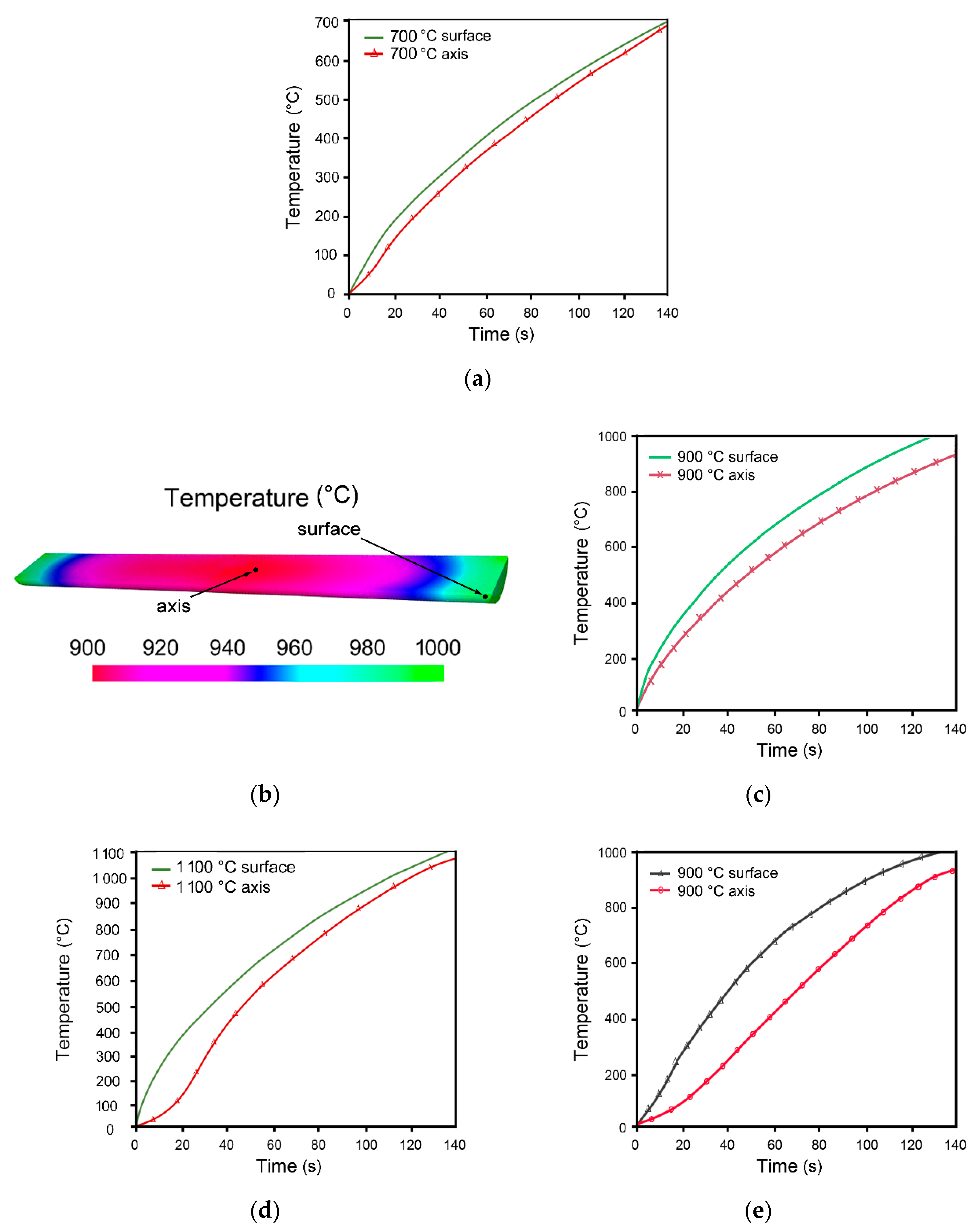
Figure 7a,c,d depict the developments of temperatures as dependent on heating time for two individual locations within the heated workpiece—on its surface and in the longitudinal axis (schematic depictions of the measured locations are depicted on the longitudinal cut through the workpiece in Figure 7b)—during heating, using the currents of I = 70, 90, and 120 A, to the target deformation temperatures of 700 °C, 900 °C, and 1100 °C, respectively. The mentioned figures show that the courses of the curves for the modeled variants differed significantly. The smallest temperature gradient between the surface and axial regions of the WNiCo workpiece was observed for the current of 70 A, i.e., the target temperature of 700 °C (Figure 7a). Increasing the target heating temperature then resulted in increasing the observed temperature gradient across the workpiece. On the other hand, despite the fact that the temperature of 700 °C was reached in both the monitored locations throughout the workpiece within the required heating time of 140 s, the heating regime selected for the target temperature of 700 °C did not introduce the required decrease in the flow stress, i.e., an increase in plasticity before subsequent swaging, as further demonstrated. The results of the prediction of the temperature distribution within the WNiCo workpiece heated to the target temperature of 900 °C (current of 90 A) document that the bulk of the workpiece exhibited the minimum required temperature of 900 °C already after 130 s of heating (Figure 7b,c). The maximum predicted gradient between the workpiece surface and axial temperatures during heating was lower than 100 °C. Figure 7d then depicts the development of temperatures within the workpiece during induction heating to the temperature of 1100 °C, i.e., with the current of 120 A. This heating regime imparted intriguing temperature behavior; at the beginning of heating, increases in temperature in the axial workpiece region were evidently delayed compared to the temperature in the surface region, which was relatively quick from the beginning and during the entire heating process. The figure also shows that the target heating temperature was achieved already before the maximum heating time of 140 s. Nevertheless, the predicted temperature gradient during heating is unfavorable, since, especially at the beginning of heating, temperature differences across the workpiece can result in the development of cracks and defects. Additionally, other phenomena, such as the quick oxidation of the surface, start to occur. For this reason, the temperature regime with the target temperature of 900 °C was selected as optimal from the viewpoint of heating time vs. achieved temperature, as well as from the viewpoint of predicted temperature gradient.
Last but not least, Figure 7e documents the temperatures in the axial and surface workpiece regions measured during the experimental induction heating to the deformation temperature of 900 °C. As evident from the experimental results, the temperature gradient between the axial and surface workpiece regions developed from the very beginning of heating (Figure 7e), and started to diminish at the heating time of ~120 s. Obviously, the increases in the experimentally measured temperatures in both the workpiece regions at the beginning of heating were not as steep as in the simulation. Nevertheless, at the time of ~60 s of heating, the experimental curve for the workpiece surface temperature (Figure 7d) increased above both the numerically predicted curves (Figure 7b). The temperature gradient between the axial and surface workpiece regions was up to 2.5 times higher in the experiment than in the simulation. Nevertheless, the workpiece final surface and axial temperatures predicted by the simulation and acquired experimentally corresponded sufficiently. At the heating time of 140 s, the experimentally observed temperatures (Figure 7d) corresponded well to the predicted final heating temperatures (Figure 7b).
4.2. Experimental Swaging
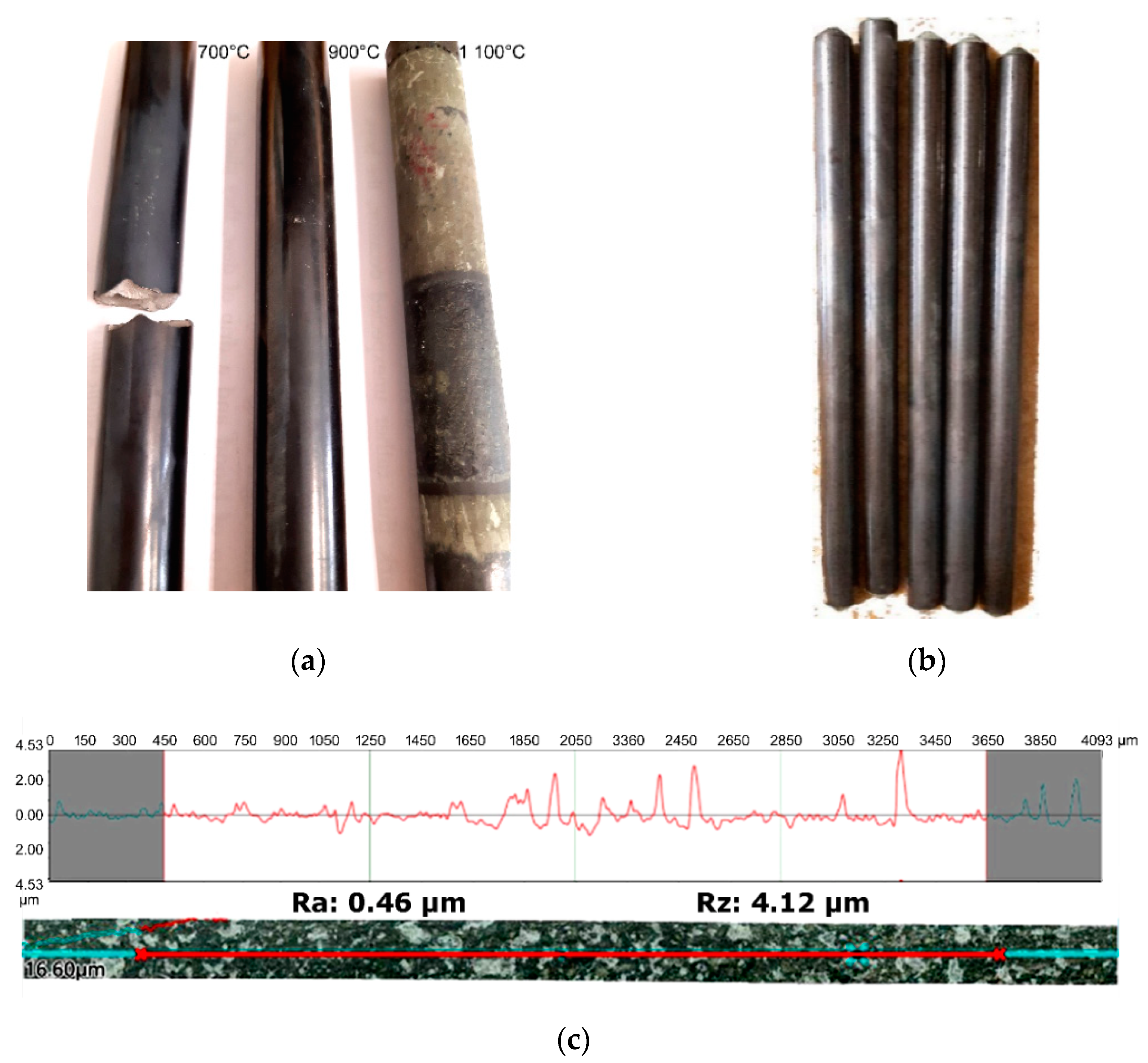
For all the three heating regimes, the workpieces were experimentally swaged immediately after the induction heating procedures. Figure 8a depicts the final billets swaged at 700 °C, 900 °C, and 1100 °C. The figure clearly shows that the temperature of 700 °C was not sufficient for the heating of the bulk of the WNiCo workpiece, as the billet exhibited brittle cracking during swaging (insufficient plasticity). On the other hand, the swaging temperature of 1100 °C provided sufficient plasticity during swaging, but resulted in the oxidation of the swaged piece’s surface. Swaging at 900 °C was the most favorable, as the final swaged piece exhibited a smooth and oxidation-free surface (Figure 8a).
In order to verify the (industrial) applicability of the most favorable induction heating procedure, five workpieces were subjected to heating to 900 °C and subsequent swaging—the final swaged billets can be seen in Figure 8b. The figure shows the high quality of the swaged surfaces free of possible cracks or voids, and also free of oxidic scales. Nevertheless, to document (i.e., quantitatively characterize) the high surface quality of the swaged billets, a swaged piece pre-heated to 900 °C was subjected to 4K digital optical microscopy investigations of the surface. Prior to processing, the average roughness of a sintered piece was determined by the OM to be Ra = 1.6. Figure 8c shows the surface scan and roughness profile of a 900 °C swaged billet. As can be seen in the scan, swaging at 900 °C substantially decreased the average roughness to Ra = 0.46.
4.3. Microstructure Analyses
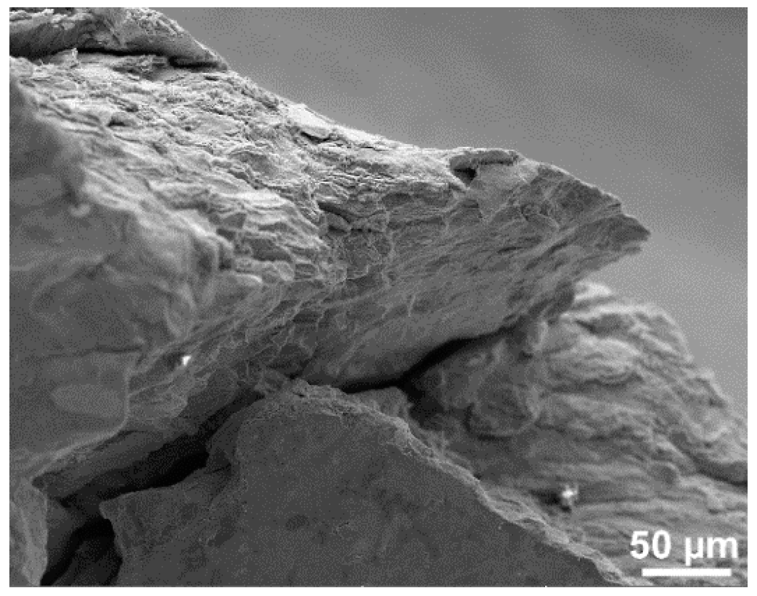
The microstructure of the sintered piece was depicted in Figure 6b. The mentioned figure acquired from a cross-sectional cut clearly shows the homogeneous void-free microstructure of the sintered state, consisting of equiaxed tungsten agglomerates embedded in the NiCo-based matrix. Figure 9 depicts a detail of the fracture of the broken swaged piece processed at 700 °C; further microstructure analyses were not worth performing for this piece. The SEM-SE images of the microstructures acquired from the subsurface (0.5 mm below the swaged surface) and axial regions of the cross-sectional cuts of the swaged pieces pre-heated via induction to 900 °C and 1100 °C are depicted in Figure 10a–d, respectively. As can be seen in Figure 10a,b, both the regions of the swaged piece deformed at 900 °C exhibited slightly elongated deformed tungsten agglomerates (when compared to the sintered state), which confirms the imposed shear strain required to positively affect the entire bulk of the swaged material. The figures also demonstrate that the inter-agglomerate spacing was smaller in the subsurface swaged piece region (Figure 10a), which confirms the effect of the shear strain to be more intense at the periphery of the workpiece (this finding corresponds to the nature of the rotary swaging process [52,53,54]). This phenomenon was even more pronounced for the swaged piece pre-heated to the temperature of 1100 °C; the subsurface region of this swaged bar exhibited a severely sheared inhomogeneous microstructure (Figure 10c), especially in the direction of the outermost surface of the swaged piece (right hand side of Figure 10c). Contrary to this finding, the axial region of the bar swaged at 1100 °C (Figure 10d) featured tungsten agglomerates of more or less homogeneous round shapes.
5. Discussion
The comparison of the numerical approaches revealed that both the software packages provide reliable results in spite of using different computational models. The observed differences between the results can primarily be attributed to the fact that the Forge NxT model calculates in 3D space, whereas the ANSYS-Maxwell model works in 2D space. Furthermore, both the models featured simplifications to maintain a reasonable computational time. Nevertheless, the investigated electromagnetic parameters were comparable in both the models, which verified their applicability.
Forge NxT was further used to perform three simulations of induction heating of WNiCo workpieces to the target deformation temperatures of 700, 900, and 1100 °C. Together with the simulations, experimental induction heating and subsequent swaging of WNiCo workpieces at the selected temperatures was performed. Experimental swaging at 900 °C turned out to be the most favorable solution, since the workpiece pre-heated to 700 °C exhibited brittle cracking during swaging, and the workpiece pre-heated to 1100 °C exhibited evident surface oxidation. Furthermore, an experimental measurement of temperatures in the axial and surface regions of the WNiCo workpiece pre-heated to 900 °C exhibited satisfactory correlations with the predicted results; the final temperatures in both the regions correlated despite the fact that their developments in prediction and experiment slightly differed.
As evident from the microstructure observations of the piece swaged at 900 °C (Figure 9b,c), both its axial and subsurface regions featured deformed tungsten agglomerates (compared to the equiaxed agglomerates within the sintered microstructure, Figure 6b), which points to the sufficient heating of the bulk of the workpiece before processing. The inter-agglomerate spacing was shorter in the subsurface workpiece region due to the direct effect of the swaging dies. The shear strain incrementally imposed upon the workpiece by the rotating swaging dies is the most intense in the workpiece subsurface region [53,54,55]. This phenomenon also affected the subsurface microstructure of the workpiece swaged at 1100 °C, however with a higher intensity due to the decreased flow stress of the matrix at the elevated temperature [56]. As depicted in Figure 9d, this region featured shear bands and microstructure inhomogeneity, which could introduce residual stress and cause a possible decrease in the lifetime of the final product (these phenomena are planned to be investigated in greater detail in a following study). A previously published study dealt with experimental and numerical investigations of the deformation behavior of a WNiCo workpiece pre-heated in an electric furnace during warm rotary swaging [18]. The reported results revealed the absolute effective strain after swaging to be the highest in the workpiece subsurface region, and its intensity then decreased towards the axial region. Furthermore, the initial temperature in the subsurface region was slightly higher than in the axial region, by the effect of which the flow stress of the NiCo matrix decreased and thus enabled higher deformation to proceed in the subsurface region (especially at higher temperatures). The comparison of the herein presented results of the microstructure analyses of the induction heated swaged piece with the previously published results of the analyses of the swaged piece pre-heated in a furnace thus exhibits a satisfactory correlation. This fact documents that the induction heating did not negatively affect the microstructure of the swaged billet despite the very short heating time. In other words, the substantially reduced heating time, i.e., intensified heating process, did not induce undesirable development of cracks or voids during the subsequent swaging (for optimized heating process). On the other hand, the rapid heating resulted in the elimination of surface oxidation (when optimized), as the analyses of the swaged piece surface showed a substantial reduction in surface roughness compared to the sintered state. The surface of the swaged piece pre-heated to 900 °C via induction did not exhibit any substantial oxidation when compared to the previously published study, the workpiece in which was pre-heated to 900 °C in a furnace before swaging [18]; the mentioned study documented the surface quality of the induction heated swaged piece to be higher than the surface quality of the swaged piece heated in an electric furnace.
6. Conclusions
The presented study focused on the optimization of the induction heating regime and proposed a suitable deformation (swaging) temperature for pre-sintered powder-based WNiCo tungsten heavy alloy workpieces. The numerical predictions and experimental investigations revealed that the optimum swaging regime consists of an induction heating time of 140 s and a deformation temperature of 900 °C. The lower heating temperature (700 °C) resulted in cracking during swaging, while the higher temperature (1100 °C) introduced surface oxidation and microstructure inhomogeneity. Swaging at 900 °C provided the workpieces with homogeneous circular shapes and oxidation-free surfaces. The rapid heating thus did not negatively affect the microstructure, while, on the other hand, it affected positively the surface quality of the swaged billets. The microstructures in the axial and subsurface regions of the piece swaged at 900 °C exhibited deformed tungsten agglomerates, which points to the effect of the shear strain involving the bulk of the swaged piece. Considering the fact that rotary swaging is an industrially applied technology following which no additional surface treatment in order to increase the surface quality is needed, the experiment proved the practical (industrial) applicability of the designed procedure.
Author Contributions
The contributions of the individual authors were the following: methodology, L.K., A.M. and Z.K.; numerical investigations, R.P., and M.M.; experimental validation, L.K., A.M. and Z.K.; microscopy investigation and evaluation, L.K.; writing—original draft preparation, L.K., A.M. and Z.K.; writing—review and editing, L.K., A.M., and Z.K.; project administration, A.M.; funding acquisition, A.M. and R.P. All authors have read and agreed to the published version of the manuscript.
Funding
The authors acknowledge the financial support of the SP2020/34 project of specific research of VSB—Technical University of Ostrava, FV40286 TRIO programme by Ministry of Industry and Trade, as well as the project no. CZ.1.05/2.1.00/19.0387 “Development of research and development basis of RMSTC” within the frame of the operation program Research and Development for Innovations financed by the Structural Funds EU and from the state budget of the Czech Republic.
Conflicts of Interest
The authors declare no conflict of interest. The funders had no role in the design of the study; in the collection, analyses, or interpretation of data; in the writing of the manuscript, or in the decision to publish the results.
References
- Dong, H.; Zhao, Y.; Yuan, H.; Hu, X.; Yang, Z. A Simplified Calculation Method of Heat Source Model for Induction Heating. Materials 2019, 12, 2938. [Google Scholar] [CrossRef] [PubMed] [Green Version]
- Di Luozzo, N.; Fontana, M.; Arcondo, B. Modelling of induction heating of carbon steel tubes: Mathematical analysis, numerical simulation and validation. J. Alloys Compd. 2012, 536, S564–S568. [Google Scholar] [CrossRef]
- Mühlbauer, A. History of Induction Heating and Melting, 1st ed.; Vulkan-Verlag GmbH: Essen, Germany, 2008; p. 202. [Google Scholar]
- Baake, E. Induction Heating: Heating|Hardening|Annealing|Brazing|Welding, 1st ed.; Vulkan-Verlag GmbH: Essen, Germany, 2016; p. 56. [Google Scholar]
- Zhao, Y.-Q.; Han, Y.; Xiao, Y. An asynchronous dual-frequency induction heating process for bevel gears. Appl. Therm. Eng. 2020, 169, 114981. [Google Scholar] [CrossRef]
- Bao, L.; Wang, B.; You, X.; Li, H.; Gu, Y.; Liu, W. Numerical and experimental research on localized induction heating process for hot stamping steel sheets. Int. J. Heat Mass Transf. 2020, 151, 119422. [Google Scholar] [CrossRef]
- Verlinden, B.; Driver, J.; Samajdar, I.; Doherty, R.D. Thermo-Mechanical Processing of Metallic Materials; Elsevier: Amsterdam, The Netherlands, 2007; p. 96. [Google Scholar]
- Kunčická, L.; Kocich, R.; Hervoches, C.; Macháčková, A. Study of structure and residual stresses in cold rotary swaged tungsten heavy alloy. Mater. Sci. Eng. A 2017, 704, 25–31. [Google Scholar] [CrossRef]
- Thomasová, M.; Seiner, H.; Sedlak, P.; Frost, M.; Ševčík, M.; Szurman, I.; Kocich, R.; Drahokoupil, J.; Sittner, P.; Landa, M. Evolution of macroscopic elastic moduli of martensitic polycrystalline NiTi and NiTiCu shape memory alloys with pseudoplastic straining. Acta Mater. 2017, 123, 146–156. [Google Scholar] [CrossRef]
- Montufar, E.B.; Horynová, M.; Casas-Luna, M.; Diaz-de-la-Torre, S.; Celko, L.; Klakurková, L.; Spotz, Z.; Diéguez-Trejo, G.; Fohlerová, Z.; Dvorak, K.; et al. Spark Plasma Sintering of Load-Bearing Iron–Carbon Nanotube-Tricalcium Phosphate CerMets for Orthopaedic Applications. JOM 2016, 68, 1134–1142. [Google Scholar] [CrossRef]
- Ročňáková, I.; Slámečka, K.; Montufar, E.B.; Remešová, M.; Dyčková, L.; Břínek, A.; Jech, D.; Dvořák, K.; Čelko, L.; Kaiser, J. Deposition of hydroxyapatite and tricalcium phosphate coatings by suspension plasma spraying: Effects of torch speed. J. Eur. Ceram. Soc. 2018, 38, 5489–5496. [Google Scholar] [CrossRef]
- Bay, F.; Labbe, V.; Favennec, Y.; Chenot, J.L. A numerical model for induction heating processes coupling electromagnetism and thermomechanics. Int. J. Numer. Methods Eng. 2003, 58, 839–867. [Google Scholar] [CrossRef]
- Liu, F.; Shi, Y.; Lei, X. Numerical investigation of the temperature field of a metal plate during high-frequency induction heat forming. Proc. Inst. Mech. Eng. Part C J. Mech. Eng. Sci. 2009, 223, 979–986. [Google Scholar] [CrossRef]
- Riccio, A.; Russo, A.; Raimondo, A.; Cirillo, P.; Caraviello, A. A numerical/experimental study on the induction heating of adhesives for composite materials bonding. Mater. Today Commun. 2018, 15, 203–213. [Google Scholar] [CrossRef]
- Park, Z.S.; Lee, S.-J.; Lee, T.; Kim, J.H.; Moon, Y.H. Fabrication of long tubular parts made of tungsten-heavy alloys by inductive bonding of multiple tubes. Int. J. Refract. Met. Hard Mater. 2019, 85, 105058. [Google Scholar] [CrossRef]
- Kocich, R.; Kunčická, L.; Dohnalík, D.; Macháčková, A.; Šofer, M. Cold rotary swaging of a tungsten heavy alloy: Numerical and experimental investigations. Int. J. Refract. Met. Hard Mater. 2016, 61, 264–272. [Google Scholar] [CrossRef]
- Hu, K.; Wang, G.; Li, X.; Qu, S. Microstructure and formation mechanism in a surface carburized tungsten heavy alloy. J. Alloys Compd. 2019, 787, 560–569. [Google Scholar] [CrossRef]
- Kunčická, L.; Macháčková, A.; Lavery, N.P.; Kocich, R.; Cullen, J.C.T.; Hlaváč, L.M. Effect of thermomechanical processing via rotary swaging on properties and residual stress within tungsten heavy alloy. Int. J. Refract. Met. Hard Mater. 2020, 87, 105120. [Google Scholar] [CrossRef]
- Dvorak, K.; Dolak, D.; Vsiansky, D.; Dobrovolny, P. Evaluation of the grindability of recycled glass in the production of blended cements. Mater. Technol. 2016, 50, 729–734. [Google Scholar] [CrossRef]
- Hafızoğlu, H.; Durlu, N. Effect of sintering temperature on the high strain rate-deformation of tungsten heavy alloys. Int. J. Impact Eng. 2018, 121, 44–54. [Google Scholar] [CrossRef]
- Kumari, A.; Prabhu, G.; Sankaranarayana, M.; Nandy, T.K. Effect of solution treatment temperature and cooling rate on the mechanical properties of tungsten heavy alloy. Mater. Sci. Eng. A 2017, 688, 225–236. [Google Scholar] [CrossRef]
- Das, J.; Rao, G.A.; Pabi, S.K.; Sankaranarayana, M.; Nandy, T.K. Thermo-mechanical processing, microstructure and tensile properties of a tungsten heavy alloy. Mater. Sci. Eng. A 2014, 613, 48–59. [Google Scholar] [CrossRef]
- Segal, V. Review: Modes and processes of severe plastic deformation (SPD). Materials 2018, 11, 1175. [Google Scholar] [CrossRef] [Green Version]
- Hlaváč, L.M.; Kocich, R.; Gembalová, L.; Jonšta, P.; Hlaváčová, I.M. AWJ cutting of copper processed by ECAP. Int. J. Adv. Manuf. Technol. 2016, 86, 885–894. [Google Scholar] [CrossRef]
- Furukawa, M.; Horita, Z.; Nemoto, M.; Langdon, T.G. Review: Processing of metals by equal-channel angular pressing. J. Mater. Sci. 2001, 36, 2835–2843. [Google Scholar] [CrossRef]
- Kocich, R.; Szurman, I.; Kursa, M.; Fiala, J. Investigation of influence of preparation and heat treatment on deformation behaviour of the alloy NiTi after ECAE. Mater. Sci. Eng. A 2009, 512, 100–104. [Google Scholar] [CrossRef]
- Kocich, R.; Kunčická, L.; Macháčková, A. Twist Channel Multi-Angular Pressing ( TCMAP ) as a method for increasing the efficiency of SPD. IOP Conf. Ser. Mater. Sci. Eng. 2014, 63, 012006. [Google Scholar] [CrossRef]
- Kunčická, L.; Kocich, R.; Král, P.; Pohludka, M.; Marek, M. Effect of strain path on severely deformed aluminium. Mater. Lett. 2016, 180, 280–283. [Google Scholar] [CrossRef]
- Kunčická, L.; Kocich, R.; Drápala, J.; Andreyachshenko, V.A. FEM simulations and comparison of the ecap and ECAP-PBP influence on Ti6Al4V alloy’s deformation behaviour. In Proceedings of the 22nd International Conference on Metallurgy and Materials, Bron, Czech Republic, 15–17 May 2013; pp. 391–396. [Google Scholar]
- Xia, K.; Wu, X. Back pressure equal channel angular consolidation of pure Al particles. Scr. Mater. 2005, 53, 1225–1229. [Google Scholar] [CrossRef]
- Edalati, K.; Horita, Z. A review on high-pressure torsion (HPT) from 1935 to 1988. Mater. Sci. Eng. A 2016, 652, 325–352. [Google Scholar] [CrossRef]
- Kunčická, L.; Lowe, T.C.; Davis, C.F.; Kocich, R.; Pohludka, M. Synthesis of an Al/Al2O3 composite by severe plastic deformation. Mater. Sci. Eng. A 2015, 646, 234–241. [Google Scholar] [CrossRef]
- Derakhshan, J.F.; Parsa, M.H.; Jafarian, H.R. Microstructure and mechanical properties variations of pure aluminum subjected to one pass of ECAP-Conform process. Mater. Sci. Eng. A 2019, 747, 120–129. [Google Scholar] [CrossRef]
- Kocich, R.; Macháčková, A.; Fojtík, F. Comparison of strain and stress conditions in conventional and ARB rolling processes. Int. J. Mech. Sci. 2012, 64, 54–61. [Google Scholar] [CrossRef]
- Kocich, R.; Kunčická, L.; Král, P.; Strunz, P. Characterization of innovative rotary swaged Cu-Al clad composite wire conductors. Mater. Des. 2018, 160, 828–835. [Google Scholar] [CrossRef]
- Kunčická, L.; Kocich, R.; Strunz, P.; Macháčková, A. Texture and residual stress within rotary swaged Cu/Al clad composites. Mater. Lett. 2018, 230, 88–91. [Google Scholar] [CrossRef]
- Kunčická, L.; Král, P.; Dvořák, J.; Kocich, R. Texture evolution in biocompatible mg-y-re alloy after friction stir processing. Metals 2019, 9, 1181. [Google Scholar] [CrossRef] [Green Version]
- Zhang, Q.; Jin, K.; Mu, D. Tube/tube joining technology by using rotary swaging forming method. J. Mater. Process. Technol. 2014, 214, 2085–2094. [Google Scholar] [CrossRef]
- Kunčická, L.; Kocich, R.; Lowe, T.C. Advances in metals and alloys for joint replacement. Prog. Mater. Sci. 2017, 88, 232–280. [Google Scholar] [CrossRef]
- Gan, W.M.M.; Huang, Y.D.D.; Wang, R.; Zhong, Z.Y.Y.; Hort, N.; Kainer, K.U.U.; Schell, N.; Brokmeier, H.-G.G.; Schreyer, A. Bulk and local textures of pure magnesium processed by rotary swaging. J. Magnes. Alloys 2013, 1, 341–345. [Google Scholar] [CrossRef] [Green Version]
- Kunčická, L.; Kocich, R. Deformation behaviour of Cu-Al clad composites produced by rotary swaging. IOP Conf. Ser. Mater. Sci. Eng. 2018, 369, 012029. [Google Scholar] [CrossRef]
- Simpson, P.G. Induction Heating—Coil and System Design, 1st ed.; McGraw-Hill: New York, NY, USA, 1960; p. 147. [Google Scholar]
- Rudnev, V.; Loveless, D.; Cook, R.L. Handbook of Induction Heating, 2nd ed.; Taylor & Francis Ltd.: London, UK, 2017; p. 230. [Google Scholar]
- Rudnev, V. Handbook of Induction Heating, 2nd ed.; Marcel Dekker: New York, NY, USA, 2003; p. 128. [Google Scholar]
- Huray, P.G. Maxwell’s Equations; John Wiley & Sons, Inc.: Hoboken, NJ, USA, 2010; p. 214. [Google Scholar]
- Bastos, J.P.A.; Sadowski, N. Electromagnetic Modeling by Finite Element Methods; Marcel Dekker: New York, NY, USA, 2003; p. 27. [Google Scholar]
- Meunier, G. The Finite Element Method for Electromagnetic Modeling; ISTE Ltd.: London, UK, 2008; Available online: https://epdf.pub/the-finite-element-method-for-electromagnetic-modeling.html (accessed on 13 May 2020).
- Marek, M. Numerical Computation of Magnetic Field and Inductivity of Power Reactor with Respect of Real Magnetic Properties of Iron Core; Springer: Berlin/Heidelberg, Germany, 2006; pp. 233–239. [Google Scholar] [CrossRef]
- Zinn, S.; Semiatin, S.L.; Electric Power Research Institute; Battelle Memorial Institute; Columbus Laboratories. Elements of Induction Heating: Design, Control, and Applications; ASM International: Amsterdam, The Netherlands, 1988. [Google Scholar]
- Klonk, S.; Bay, F. Numerical analysis of computational models for induction heat treatment of complex geometrical parts. Int. J. Microstruct. Mater. Prop. 2016, 11, 48. [Google Scholar] [CrossRef]
- Biro, O.; Preis, K. On the use of the magnetic vector potential in the finite-element analysis of three-dimensional eddy currents. IEEE Trans. Magn. 1989, 25, 3145–3159. [Google Scholar] [CrossRef]
- Zapata, J.R.A.; Bay, F. Modeling and Analysis of Electromagnetism in Magnetic Forming Processes. IEEE Trans. Magn. 2016, 52, 7004011. [Google Scholar] [CrossRef]
- Kunčická, L.; Kocich, R.; Dvořák, K.; Macháčková, A. Rotary swaged laminated Cu-Al composites, Effect of structure on residualstress and mechanical and electric properties. Mater. Sci. Eng. A 2019, 742, 743–750. [Google Scholar] [CrossRef]
- Kunčická, L.; Macháčková, A.; Krátká, L.; Kocich, R. Analysis of deformation behaviour and residual stress in rotary swaged Cu/Al clad composite wires. Materials 2019, 12, 3462. [Google Scholar] [CrossRef] [PubMed] [Green Version]
- Kocich, R.; Kunčická, L.; Davis, C.F.; Lowe, T.C.; Szurman, I.; Macháčková, A. Deformation behavior of multilayered Al-Cu clad composite during cold-swaging. Mater. Des. 2016, 90, 379–388. [Google Scholar] [CrossRef]
- Russell, A.; Lee, K.L. Structure-Property Relations in Nonferrous Metals, 1st ed.; John Wiley & Sons, Inc.: Hoboken, NJ, USA, 2005; p. 114. [Google Scholar]
Figure 1.
General principle of induction heating: schematic depiction of coil and heated workpiece (a); detailed depiction of eddy currents (b); graphical depiction of skin effect (c).
Figure 1.
General principle of induction heating: schematic depiction of coil and heated workpiece (a); detailed depiction of eddy currents (b); graphical depiction of skin effect (c).

Figure 2.
Typical B/H characteristics for paramagnetic material (i.e., tungsten) (a); permeability characteristics for paramagnetic material (i.e., tungsten) (b).
Figure 2.
Typical B/H characteristics for paramagnetic material (i.e., tungsten) (a); permeability characteristics for paramagnetic material (i.e., tungsten) (b).

Figure 3.
Initial set-up of induction heating: 3D model (Forge NxT) (a); detail of mesh of 3D model (b); 2D model (Ansys-Maxwell) (c); detail of mesh of 2D model (d). Closer details of the 3D models of heated workpiece (e) and the inductor coil (f).
Figure 3.
Initial set-up of induction heating: 3D model (Forge NxT) (a); detail of mesh of 3D model (b); 2D model (Ansys-Maxwell) (c); detail of mesh of 2D model (d). Closer details of the 3D models of heated workpiece (e) and the inductor coil (f).


Figure 4.
Magnetic field intensity distribution in the 2D model (a) and the 3D model (b); heat power (Joule heat) distribution in the 2D model (c) and the 3D model (d).
Figure 4.
Magnetic field intensity distribution in the 2D model (a) and the 3D model (b); heat power (Joule heat) distribution in the 2D model (c) and the 3D model (d).

Figure 5.
Schematics of induction heating and swaging process (a); photography of semi-automated laboratory manufacturing line with description of the main features (b).
Figure 5.
Schematics of induction heating and swaging process (a); photography of semi-automated laboratory manufacturing line with description of the main features (b).

Figure 6.
SEM-SE image of initial powder mixture (a); SEM-SE scan of the area’s chemical composition from which was analyzed (b) the element spectrum corresponding to area presented in Figure 6b (c).
Figure 6.
SEM-SE image of initial powder mixture (a); SEM-SE scan of the area’s chemical composition from which was analyzed (b) the element spectrum corresponding to area presented in Figure 6b (c).

Figure 7.
Heating time- and temperature-dependences of the axial and surface workpiece regions during: simulated heating to 700 °C (a); simulated heating to 900 °C (c); simulated heating to 1100 °C (d); experimental heating to 900 °C (e). Temperature distribution throughout billet heated to 900 °C (b).

Figure 8.
Experimental WNiCo billets swaged at 700 °C, 900 °C, and 1100 °C (a); five WNiCo billets swaged at 900 °C (b); surface scan of billet swaged at 900 °C (acquired by KEYENCE VHX7000) (c).
Figure 8.
Experimental WNiCo billets swaged at 700 °C, 900 °C, and 1100 °C (a); five WNiCo billets swaged at 900 °C (b); surface scan of billet swaged at 900 °C (acquired by KEYENCE VHX7000) (c).

Figure 9.
SEM-SE image of detail of cracked swaged piece processed at 700 °C.

Figure 10.
SEM-SE images of 900 °C swaged piece subsurface region (a), 900 °C swaged piece axial region (b), 1100 °C swaged piece subsurface region (c), 1100 °C swaged piece axial region (d).
Figure 10.
SEM-SE images of 900 °C swaged piece subsurface region (a), 900 °C swaged piece axial region (b), 1100 °C swaged piece subsurface region (c), 1100 °C swaged piece axial region (d).

Publisher’s Note: MDPI stays neutral with regard to jurisdictional claims in published maps and institutional affiliations. |
© 2020 by the authors. Licensee MDPI, Basel, Switzerland. This article is an open access article distributed under the terms and conditions of the Creative Commons Attribution (CC BY) license (http://creativecommons.org/licenses/by/4.0/).
Share and Cite
MDPI and ACS Style
Kunčická, L.; Macháčková, A.; Petrmichl, R.; Klečková, Z.; Marek, M. Optimizing Induction Heating of WNiCo Billets Processed via Intensive Plastic Deformation. Appl. Sci. 2020, 10, 8125. https://doi.org/10.3390/app10228125
AMA Style
Kunčická L, Macháčková A, Petrmichl R, Klečková Z, Marek M. Optimizing Induction Heating of WNiCo Billets Processed via Intensive Plastic Deformation. Applied Sciences. 2020; 10(22):8125. https://doi.org/10.3390/app10228125
Chicago/Turabian StyleKunčická, Lenka, Adéla Macháčková, Rudolf Petrmichl, Zuzana Klečková, and Martin Marek. 2020. "Optimizing Induction Heating of WNiCo Billets Processed via Intensive Plastic Deformation" Applied Sciences 10, no. 22: 8125. https://doi.org/10.3390/app10228125
Note that from the first issue of 2016, this journal uses article numbers instead of page numbers. See further details here.