Article

On the Structural and Chemical Homogeneity of Spark Plasma Sintered Tungsten

1
Institute of Plasma Physics, Za Slovankou 3, 18200 Prague, Czech Republic
2
Faculty of Nuclear Sciences and Physical Engineering, Czech Technical University in Prague, Břehová 7, 11519 Prague, Czech Republic
3
Department of Metals and Corrosion Engineering, University of Chemistry and Technology, Prague, Technická 5, 166 28 Prague, Czech Republic
4
Faculty of Mathematics and Physics, Charles University, Ke Karlovu 3, 12116 Prague, Czech Republic
5
Institute of Physics of the Czech Academy of Sciences, Na Slovance 2, 182 21 Prague, Czech Republic
*
Author to whom correspondence should be addressed.
former affiliation: Leco Instrumente Plzeň, spol. s r.o., Plzeň, Czechia.
Metals 2019, 9(8), 879; https://doi.org/10.3390/met9080879
Submission received: 27 June 2019 / Revised: 1 August 2019 / Accepted: 6 August 2019 / Published: 10 August 2019
(This article belongs to the Special Issue Advanced Tungsten Materials)

Abstract

:
Tungsten-based materials are the prime candidate plasma-facing materials for future fusion reactors, such as DEMO. Spark plasma sintering is a prospective fabrication technology with several advantageous features. The concurrent application of electric current, temperature and pressure enhances the sintering process, allowing for lower temperatures and shorter sintering times than traditional powder metallurgy processes. This in turn helps to avoid excessive grain growth and phase segregation in W-alloys. This study is focused on several factors that may influence the homogeneity of the sintered compacts—namely the diffusion of carbon from the graphite die, purity of the powder and sintering conditions. The following characteristics of spark plasma-sintered tungsten compacts were studied: composition (especially carbon and oxygen content), porosity, mechanical properties (hardness and fracture strength), and thermal diffusivity. The effects of the abovementioned processing factors were quantified, and local variations of selected properties were assessed.

1. Introduction

Tungsten is a well-known refractory material with superior qualities among metals. It possesses the highest melting point, high density and modulus, high strength at elevated temperatures, and high erosion resistance. Together with good thermal conductivity, low physical sputtering yield and low reactivity with hydrogen, these make tungsten a favorable material in nuclear fusion applications [1,2]. Therefore, tungsten (or its modifications) are planned as a plasma-facing material for highly-loaded plasma facing components, such as the divertor. However, due to high atomic number (Z), radiation losses of tungsten are significant and therefore tungsten presence in fusion plasma is highly undesired and is to be kept on as low a level as possible. Furthermore, tungsten also exhibits certain intrinsic brittleness at low temperatures and reduction of mechanical properties due to recrystallization at high temperatures, which may lead to poor thermal shock resistance during thermal cycling [1]. From this point of view, small grain size, high purity, and good strength of the grain boundaries are generally beneficial [3]. Fine grains are also helpful for irradiation resistance, as the grain boundaries act as sinks to irradiation-induced defects [4]. These and other properties of tungsten can be to a large extent influenced by processing conditions.
Spark plasma sintering (SPS, also called Field Assisted Sintering Technology, FAST) is a progressive technique to consolidate various materials, metals as well as ceramics, glass etc. Relatively low temperatures, high heating rates and short processing times—compared to traditional sintering techniques—are generally favorable for the retention of fine grains. In SPS, the sintered material in the form of powder is introduced into a die and, subsequently, high-intensity (pulsed or steady) electric currents up to several thousand A and uniaxial pressure up to hundreds MPa are applied. The die and the powder are heated by Joule heating. Graphite foil is usually inserted between the powder and the die in order to eliminate undesirable bonding of sintered material to the die. Depending on the parameters and the sintered material, temperature can reach up to ~2400 °C and with suitable parameters, fully dense samples can be obtained [5,6,7]. Sintering parameters have a considerable effect on the resulting microstructure, homogeneity and other properties of the samples. Basic variables characterizing the sintering process are: (i) sintering temperature, (ii) applied pressure, and (iii) duration of the holding time at the sintering temperature. The results are also sensitive to the heating rate, manner of pressure application, die dimensions, sintering atmosphere etc.
The effects of these and other parameters on SPS samples of conductive as well as insulating materials were investigated in numerous studies [6,7,8,9,10,11]. Generally, by increasing the sintering temperature, higher relative density was obtained. Fully dense alumina samples can be obtained at 1300 °C, almost fully densified tungsten samples at 1600–1800 °C, depending on the applied pressure, holding time and initial powder grain size. The increase of the pressure and the holding time can further increase the density, i.e., decrease the temperature required for full densification. Significant grain growth can also occur; grain sizes up to 30 times the original powder size can be obtained [6,8,10]. Not only the temperature, but also the heating rate influenced the resulting microstructure—when alumina was SPS-ed in Ref. [6], with increasing heating rate, a finer microstructure with smaller grains was obtained; however, when exceeding 350 °C/min, porous structures were formed. Experiments with different sizes of the alumina powder (40 nm, 20 µm) confirmed that samples prepared from finer powder exhibit higher relative density and nearly fully dense samples can be obtained at temperatures lower by 200–300 °C compared to the coarser powder [11]. Parameters of the sintering environment (e.g., dimensions of the graphite die, additives or sintering atmosphere) were examined as well. Experiments on SPS nickel showed that samples prepared using graphite die with the same inner diameter but larger outer diameter exhibited a finer microstructure and smaller grains, although the effect on density was negligible [7].
In Ref. [8], tungsten samples with WC additive up to 10 vol% were prepared. By increasing the WC percentage, higher relative density and hardness were obtained, compared to pure tungsten samples, while the grain size was smaller. The grain size did not change with increasing WC percentage. In the same work, attention was also paid to oxygen impurities in the W powder. Powder pre-treatment by a reducing atmosphere (H2) within the SPS was applied. No effect on the density of the compacts was observed, but significantly reduced oxygen content compared to the starting powder. Similar reduction treatment on compacted powders prior to sintering was applied in Ref. [9]. It was found to significantly improve the density of the sintered material, showing also a dependence on the reduction temperature. The effect of the sintering atmosphere was also examined. Samples sintered in Ar reached higher relative density and finer grain size than samples sintered in H2. The densification in Ar was faster and increased more slowly with the sintering temperature. Huang et al. [12] and Šestan et al. [13] detected tungsten oxide in the form of WO2 as a secondary phase in sintered W; this was attributed to residual oxygen in the sintering chamber and/or impurity of the powder. While the oxidic particles effectively inhibited grain growth by pinning the grain boundaries [12], they were also shown to have potentially detrimental effects on thermal stability [13]. In Ref. [14], optimization of W sintering was performed by introducing a holding step at intermediate temperature (1200 °C) before sintering at 1500–1800 °C. This resulted in particle rearrangement, suppression of pore boundary separation and finer grains of the sintered products. Similar two-step sintering was applied by Choi et al. [15], and together with reducing powder treatment in H2 atmosphere, enabled the fabrication of extremely dense compacts (99.9% claimed).
During the sintering, a certain degree of inhomogeneity can occur, either due to spatial variation of the temperature and pressure within the volume of the powder [16,17], or due to interdiffusion of species between the powder and the surrounding materials. In Ref. [11], inhomogeneity in grain size and microhardness were observed after the sintering of alumina micro- (~20 µm) and nano-powders (40 nm). Grain size was decreasing from the sample centre to the edges, axially as well as radially. Microhardness exhibited inhomogeneity as well; the central values were lower than the values close to the surface in most measurements. The differences were more significant for the micropowder, while nanopowder samples were considerably more homogenous. These inhomogeneities were assigned to the pressure gradient—near the sample edges, the applied pressure could be lower than at the centre [11]. Calculations in Ref. [17] indicated differences around 2% in temperature and up to 40% in pressure, however, the latter applies to fully dense sample, while in powder, the pressure difference is expected to be considerably smaller.
Several studies have also been devoted to the interaction of the sintered materials with different foils in SPS. In Ref. [18], B6O was sintered in graphite foil, with or without the addition of BN coating and Ta foil. In both the latter cases, inward C diffusion was effectively suppressed, leading to a minor improvement of density and hardness but a reduction in fracture toughness. When C foil was replaced with Mo foil for SPS of CaF2 transparent ceramics, carbon concentration in the compact was reduced from 4.1 to 0.9 at%, resulting in higher transmittance and significantly larger grains [19]. Similarly, the use of Pt foil instead of C foil in SPS preparation of MgAl2O4 transparent ceramics resulted in the suppression of carbon contamination, absence of discoloration and slightly increased density [20]. In Ref. [21], spatial variation in grain size and density was studied for tungsten-heavy alloys sintered at different conditions and dimensions; C foil was used to improve the temperature homogeneity during the sintering. In Ref. [22], the effect of carbon on the reduction of intentionally oxidized Ni powders in SPS was studied in different configurations of C and Cu foils. It was shown that a direct contact with a source of carbon is critical for the elimination of the oxide, while the regions with reduced oxide films showed more pronounced inter-particle necking. In those cases, the oxygen content was even lower that in the non-oxidized starting powder. In Ref. [23], it was shown that carbon uptake can occur not only by diffusion, but also by carbon evaporation at high heating rates and penetration into the sample by open pores. Vilémová et al. [24] studied the effect of carbon diffusion on SPS-ed W-Cr alloy, using C or W foil. In the former case, inward C diffusion led to the formation of (W,Cr)2C, a decrease of the melting point compared to W2C, formation of the liquid phase and its penetration through the sintered material, associated with Cr depletion from the W+Cr solid solution. These effects were absent when W foil was used. The formation of a WC surface layer on SPS-ed W due to carbon diffusion from the graphite foil and die was observed in Ref. [13] and Ref. [10]. In the latter, additional application of BN spray did not block the carbon uptake significantly, but slowed down its diffusion.
In Ref. [25], the effect on impurities at grain boundaries on the fracture behavior of polycrystalline tungsten was studied. It was concluded that they do not have a significant influence on the fracture resistance of the boundaries. Other factors, such as the grain shape, grain size distribution, texture, dislocation density and temperature were found to have stronger effect.
In the present study, tungsten samples were prepared by SPS under various conditions. The influence of the used foil (C or W); powder state (uncleaned or cleaned by annealing in reducing atmosphere); and sintering conditions on the microstructure, porosity, mechanical and thermal properties was studied. Spatial variation of the composition as well as some of the abovementioned characteristics was also investigated.

2. Materials and Methods

The samples were prepared from tungsten powders (Global Tungsten & Powders, Bruntál, Czechia; Figure 1) via spark plasma sintering, using an SPS 10-4 (Thermal Technology, Santa Rosa, CA, USA) equipment and a 20-mm inner diameter graphite die. A variety of preparation conditions were used; these are summarized in Table 1. The parameters that were varied included the following:
-
sintering environment (graphite or tungsten foil)
-
sintering temperature (1700 or 2000 °C)
-
sintering time (2 or 15 or 60 min)
-
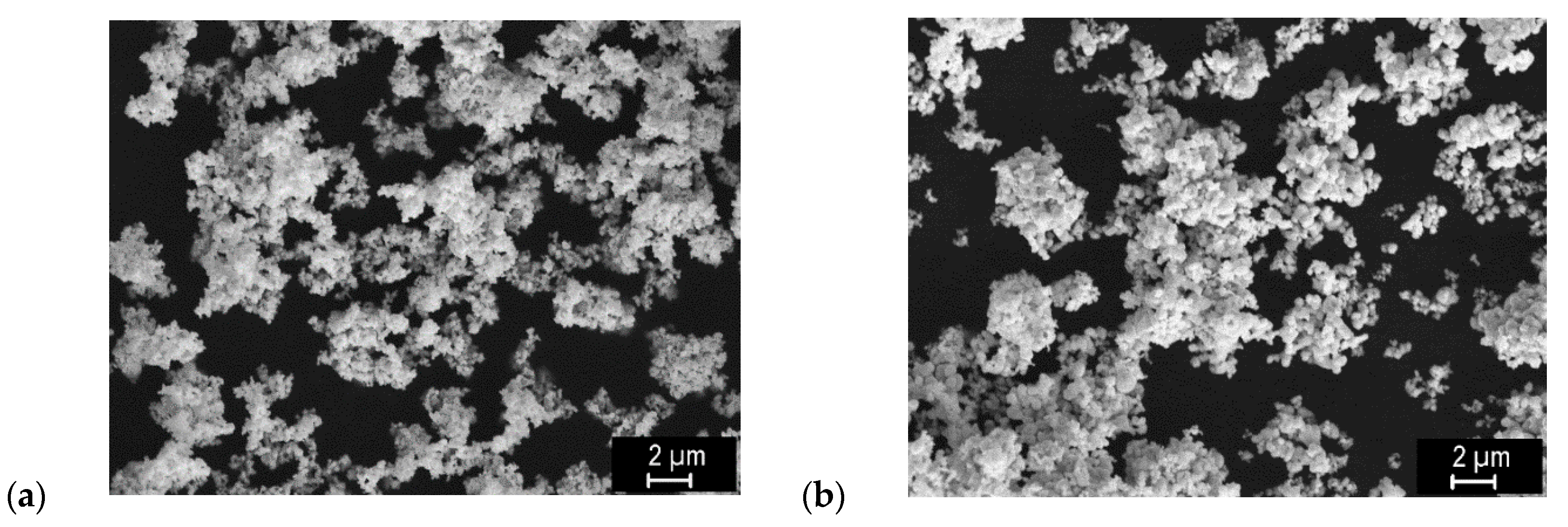
powder size (nominally 0.5 and 0.7 microns)
-
powder state (uncleaned or cleaned)
As graphite foil is conventionally used during SPS, this often results in carbon diffusion into the sample. Therefore, tungsten foil was also used with the prospect of limiting the carbon intake. Different sintering temperatures and times were applied to see the effect on carbon diffusion. While a short sintering time (typically 2–3 min) is usually needed during SPS, longer times were used on purpose in some cases to boost the carbon diffusion. The temperature was measured by a pyrometer in a hole going through the die up to 5 mm from the sample; the actual temperature in the sintered material was likely somewhat higher. The sintering took place under He atmosphere at 60 Pa, to suppress potential oxidation by the air remnants. Two powder states were also used to evaluate the effect of oxygen contamination, as minor oxidation of tungsten powders takes place during storage even at room temperature. The powder labeled as ‘cleaned’ was annealed in an Ar+7%H2 mixture at 900 °C for 1 h to remove the oxide. Prior to characterization, remnants of the foils were removed from the sintered compacts by grinding.
The samples were subject to comprehensive characterization, as described below. However, not all techniques were applied on all samples.
Microstructures of the sintered compacts—both on polished cross sections and fracture surfaces—were observed by scanning electron microscopy (SEM), using EVO MA 15 (Carl Zeiss SMT, Oberkochen, Germany) microscope. On the SEM images, porosity and grain size were determined by image analysis using ImageJ software (National Institute of Health, Bethesda, MD, USA). Five images in each region of interest were analyzed.
For determining the composition, several techniques were used. On a macroscopic scale, inert gas fusion technique was applied to determine the oxygen and carbon content in powders and pieces of the compacts, using LECO ONH836 and LECO CS844 instruments (LECO Corporation, St. Joseph, MI, USA), respectively [26]. On a microscopic scale, energy-dispersive spectrometry (EDS; XFlash 5010, Bruker, Berlin, Germany) in the SEM was used to obtain qualitative elemental maps of W, C and O on polished cross-sections and fracture surfaces. On a semi-local scale, oxygen and carbon contents were determined by glow discharge spectrometry (GDS, GD Profiler II, Horiba Jobin Yvon, Palaiseau, France) [27]. To obtain through-thickness profiles, measurements were repeated after successive grinding of layers of varying thickness (see Figure 2); at each point, GDS measurement was performed for about 30 s, during which about 7 μm of material were sputtered away in a circular area of 4 mm diameter. To enable quantitative analysis, calibration of the GDS intensities was performed using a pure W sample (Plansee, ITER-qualified grade, 99.97% purity, C < 30 ppm, O < 20 ppm) and W+WC and W+WO3 samples of known compositions prepared in-house by SPS. For these, W was mixed with WC and WO3 powders in a ball mill at two compositions each, resulting in mixtures having 1 and 1.5 wt% C and 0.8 and 1.7 wt% O. These were subsequently sintered at 2000 °C (W+WC) or 1400 °C (W+WO3) at 60 MPa for 3 min. Six-millimetre-thick pellets were cut in half along the planar surface and the innermost surface was used for the GDS measurement, to minimize the sintering environment effects. Additionally, x-ray diffraction (XRD) measurements were performed on the fracture surfaces using D8 Discover diffractometer (Bruker, Karlsruhe, Germany). Phase analysis with full profile Rietveld refinement was performed to provide a semi-quantitative comparison of tungsten oxide content.
Thermal diffusivity was determined by laser flash technique at several temperatures between 20 and 400 °C, using an LFA 1000 (Linseis, Selb, Germany) instrument. For this measurement, samples of ~2 × 10 × 10 mm dimensions were used.
Flexural strength was determined by 3-point bending using an Instron 1362 universal testing machine with a 8800 control unit (Instron, High Wycombe, UK). Supports with 5 mm diameter, support span of 14.55 mm and loading rate of 0.5 mm/min were used. Two-dimensional variation of microhardness was determined on polished cross sections of the compacts, using Qness Q10 universal micro-hardness tester (Qness, Golling an der Salzach, Austria), with Vickers indenter, 500 g load and a matrix of 19 × 11 indents.

3. Results

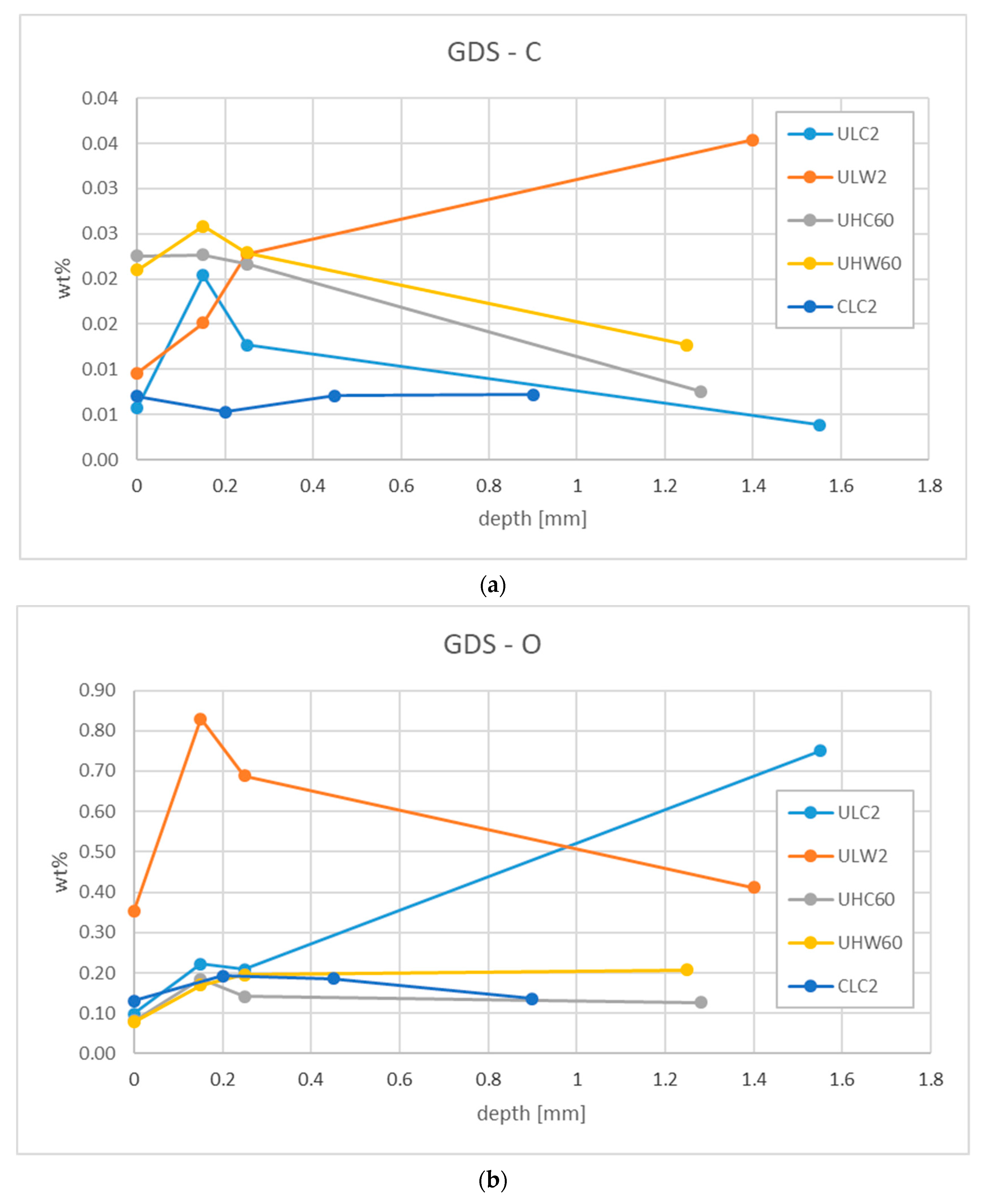
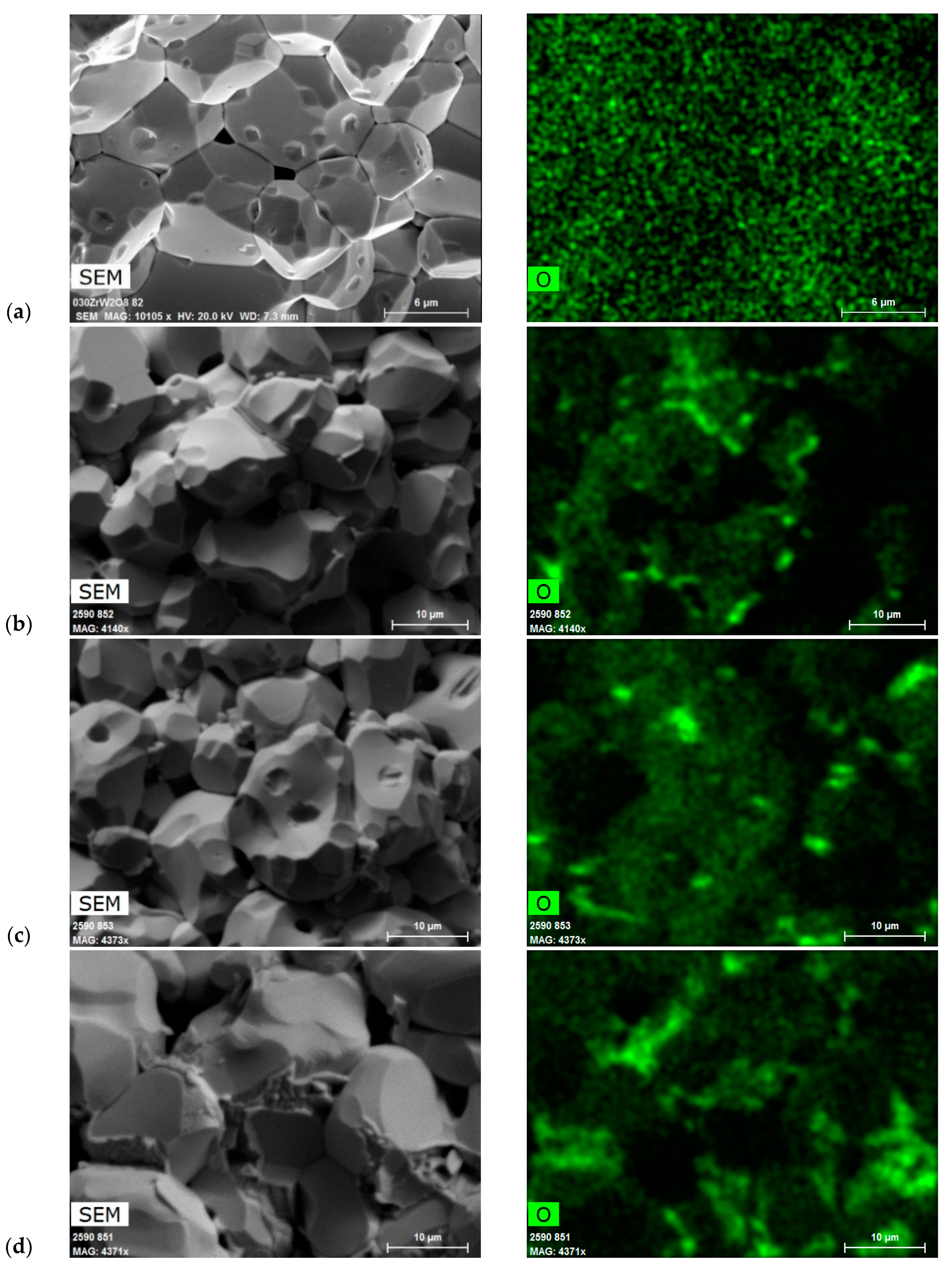
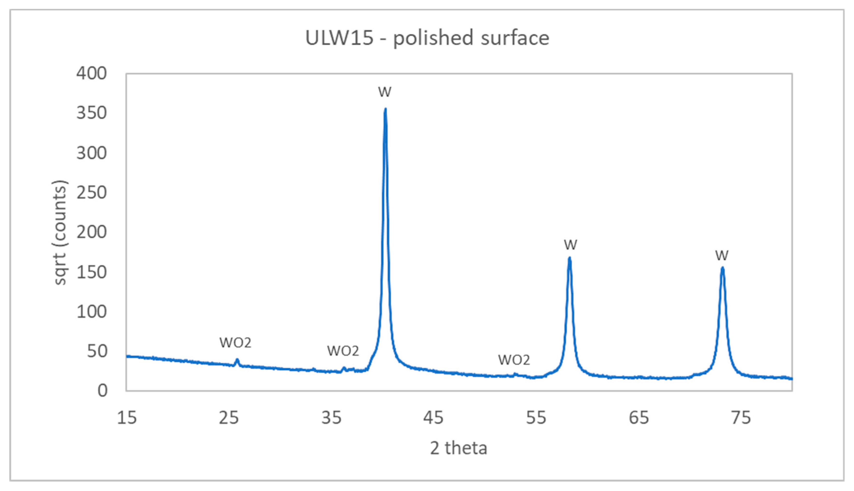
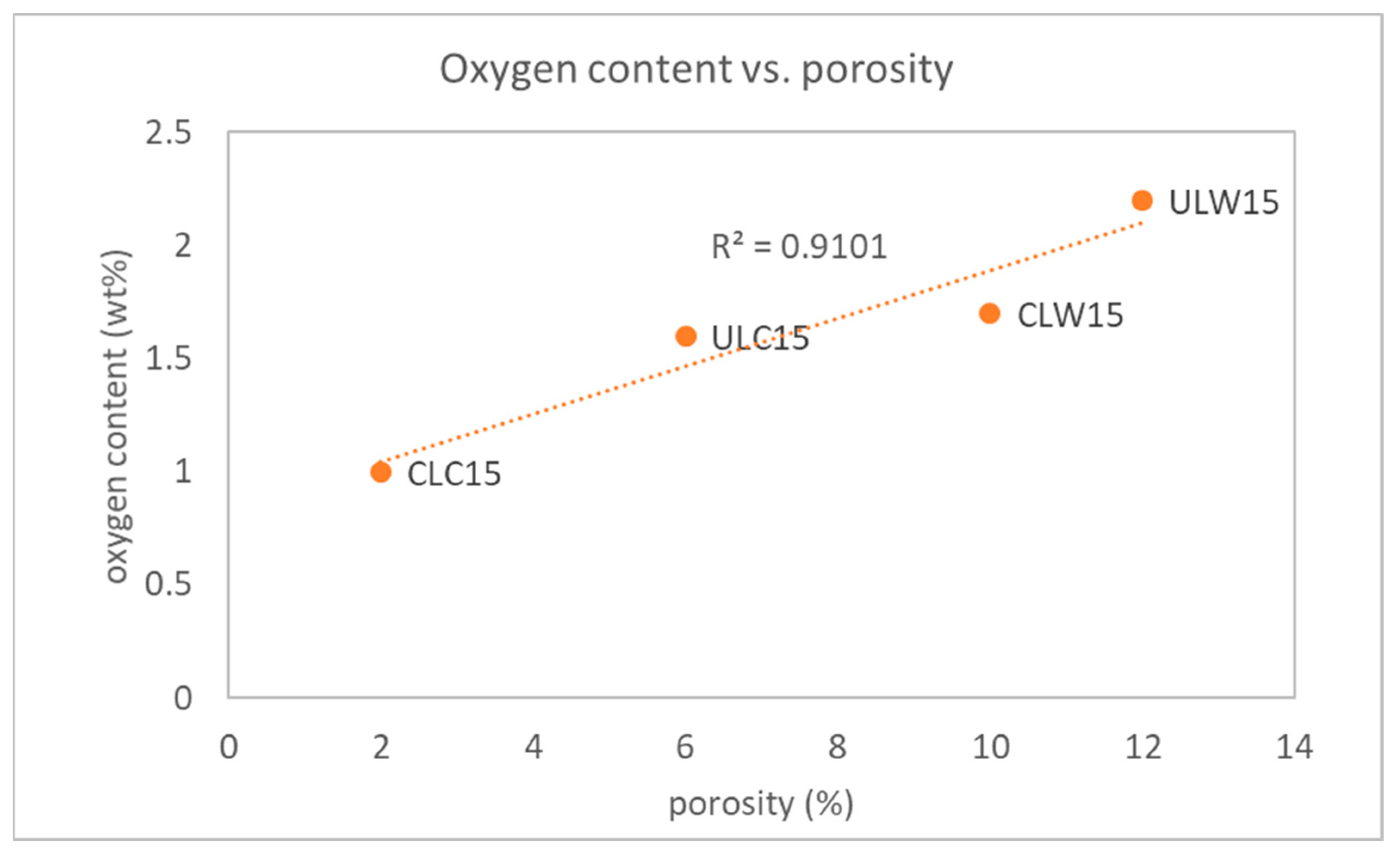
3.1. Chemical (In)homogeneity

Elements other than tungsten come from two principal sources—oxygen as an impurity in the powder, and carbon via diffusion from the graphite die and foil used during the sintering.
Initial IGF measurements on a 2 µm W powder after extended period of storage indicated 0.099 ± 0.002 wt% of oxygen, while after annealing in Ar+H2 atmosphere, this was reduced to 0.052 ± 0.001 wt%. The oxidation process is affected by the specific surface, depending on the characteristic powder size. Nominal oxygen content, as stated by the powder manufacturer, was <0.1% for the 2 µm W powder, <0.2% for the 0.7 µm W powder and <0.3% for the 0.5 µm W powder.
IGF measurements on pieces of W compacts equivalent to the ULC2 and UHC60 samples from Table 1 showed oxygen content in the 0.002 to 0.005 wt% range, i.e., smaller than found in the powder, without a clear trend with respect to the processing conditions. Carbon content was found in the 0.002 to 0.186 wt% range. While the results from different pieces of the ULC2-type samples were rather uniform, results from pieces of the UHC60-type sample were quite scattered, indicating an inhomogeneous carbon distribution in the sample. This could be expected in light of the higher sintering temperature and longer time, favoring inward C diffusion.
As the abovementioned initial results were only indicative, a more systematic study was carried out on the samples listed in Table 1.
Figure 2 shows the content of carbon and oxygen, determined by GDS at various depths from the surface to the center of the ULC2, ULW2, UHC60, UHW60 and CLC2 specimens. Concerning the carbon content, a general trend of higher values at higher sintering temperatures can be observed. Also, in most cases a slight gradient from the surface (close to the graphite foil and die) to the center can be seen. The high value found at the innermost point of the ULW2 sample is rather unexpected; we do not have any explanation for such a trend and tend to consider it an outlier (possibly caused by a local impurity or an erroneous measurement). Still, it falls within the same range as the other data points. The carbon content in the CLC2 sample is the lowest, without a distinct gradient. Overall, the carbon content is very low (~0.02 wt%). Despite this, it can have pronounced effects on the microstructure and properties, as will be shown in the following sections. Concerning the oxygen, the highest content was found in the lower-temperature samples (ULW2 and ULC2), while for the UHW60, UHC60 and CLC2 it was consistently lower and similar in all three cases. The overall trend of lower oxygen content with higher sintering temperature, as well as opposite trends of carbon and oxygen in the ULW2 and ULC2 samples (which show a through-thickness gradient), indicate that the diffusing carbon has a reducing effect. Such an effect was also reported for other materials in Refs. [28,29]. In the CLC2 sample, the lower oxygen content in the starting powder (cleaned) likely contributed to the lower final values. It should be noted that the profiles shown in Figure 2 do not necessarily reflect purely diffusion phenomena, but may also encompass carbon–oxygen reaction and their transport in the gaseous phase.
Figure 3 shows details of the fracture surfaces of the CLW15, ULW15, CLC15 and ULC15 samples and corresponding oxygen maps. As can be seen from the maps and corresponding SEM images with distinct morphologies, the oxygen impurity tends to concentrate at grain boundary junctions. This is considered to result from oxygen segregation during grain growth. This phenomenon is most pronounced for the ULW15 sample (uncleaned powder, W foil), while most homogeneous oxygen distribution was observed for the CLC15 sample (cleaned, C foil), which further supports the conclusion about the reducing effect of carbon. EDS results, despite being only semi-quantitative, also confirm this trend, see Table 2. Higher oxygen content is found for the uncleaned powder than for the cleaned powder, and for the samples sintered in W foil than for those sintered in the C foil. The same trend is also shown by the XRD results. These numbers are higher than those from the GDS, as the oxides concentrate on the grain boundaries and get exposed during the fracture (polished surface of the ULW15 sample showed 0.56 wt% WO2; Figure 4). The WO2 phase was also identified by electron diffraction in SPS W in Refs. [12,13]. It may have formed as a result of incomplete reduction of the more naturally occurring WO3 [30,31,32] or through segregation of oxygen dissolved in the W matrix or adsorbed on the W powder grains [12,33]. Contrary to oxygen impurities, present in the form of tungsten oxide, no tungsten carbide was detected in any of the XRD patterns.
Overall, the content of oxygen and carbon in the samples was very small and close to the detection limits of the applied analytical methods. Therefore, no conclusions are made from the absolute numbers, but rather the trends within and between the samples.

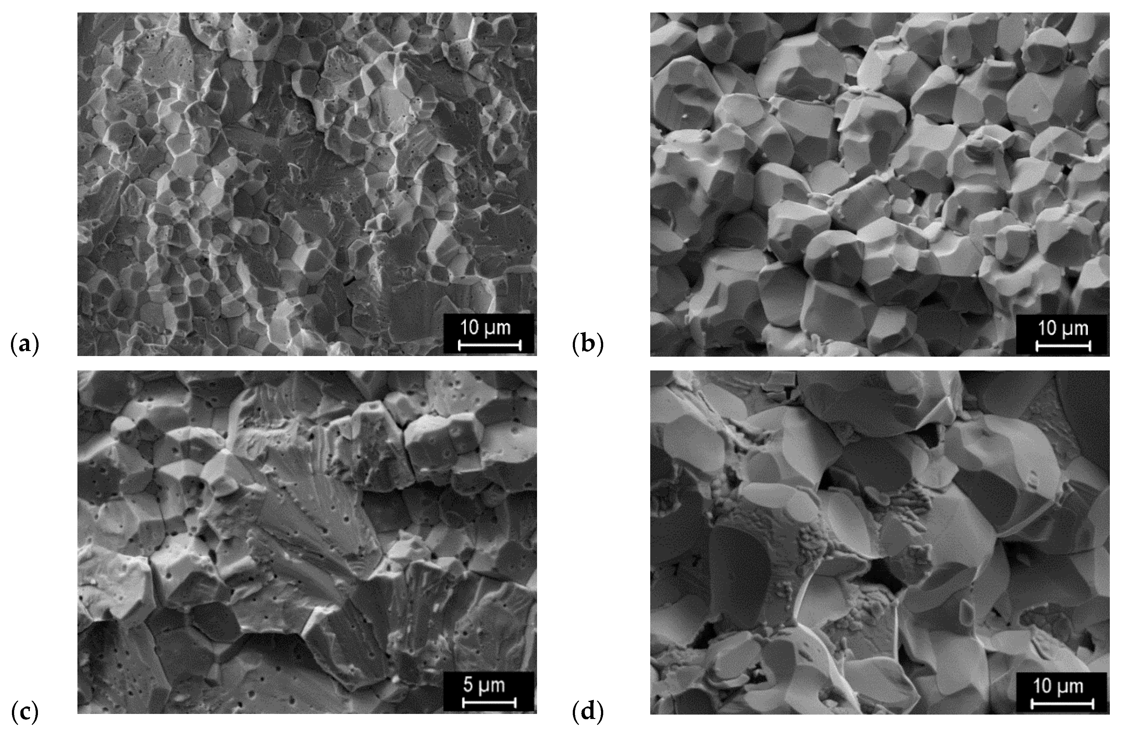
3.2. Microstructural Features

As the compositional analysis indicated a gradient from the surface towards the center of the samples, microstructural features were also analyzed in different regions within the sample. A schematic is shown in Figure 5, which represents a vertical section through half of the cylindrical SPS sample.
Representative microstructures (polished cross sections) for the top and middle regions of the CLC15, CLW15, ULC15 and ULW15 samples are shown in Figure 6. A slight variation in structure is observed near the top surface of the ULC15 and ULW15 samples, while for the CLC15 and CLW15, the structures are more uniform. Remarkable differences can be seen between the samples sintered in C and W foil and between those from standard and cleaned powder. Samples sintered in C foil generally feature lower porosity and smaller pores. Lower porosity is also observed in the samples from cleaned powder. Therefore, both C foil and powder cleaning in reducing atmosphere have a beneficial effect on decreasing the porosity. This could be attributed to enhanced surface diffusion, an important sintering mechanism, which is otherwise hindered by the surface oxidation [34,35].
Figure 7 shows representative pore size distributions for the CLC15 and CLW15 samples, obtained in the two most distant regions (cf. Figure 5), 2m (middle/center) and 2t (top/edge). In general, there were only small differences in pore size distribution between the central and near-surface region of the samples (with the exception of the ULC15 sample). A significant difference in pore size due to the foil material can be seen—larger pores result from sintering in W foil, as already indicated in Figure 6. The samples made from the uncleaned powder (not shown here) had only slightly larger pores than those from the cleaned powder. Figure 8 summarizes the trends in porosity and grain size, determined by image analysis. Overall, only a small variation in grain size was observed. The samples sintered in C foil had generally lower porosity than those sintered in W foil. The lowest porosity was obtained in samples sintered in C foil from the cleaned powder and was highest in samples sintered in W foil from the uncleaned powder. The differences between top and middle regions were again relatively small, without a distinct trend that would apply to all samples.

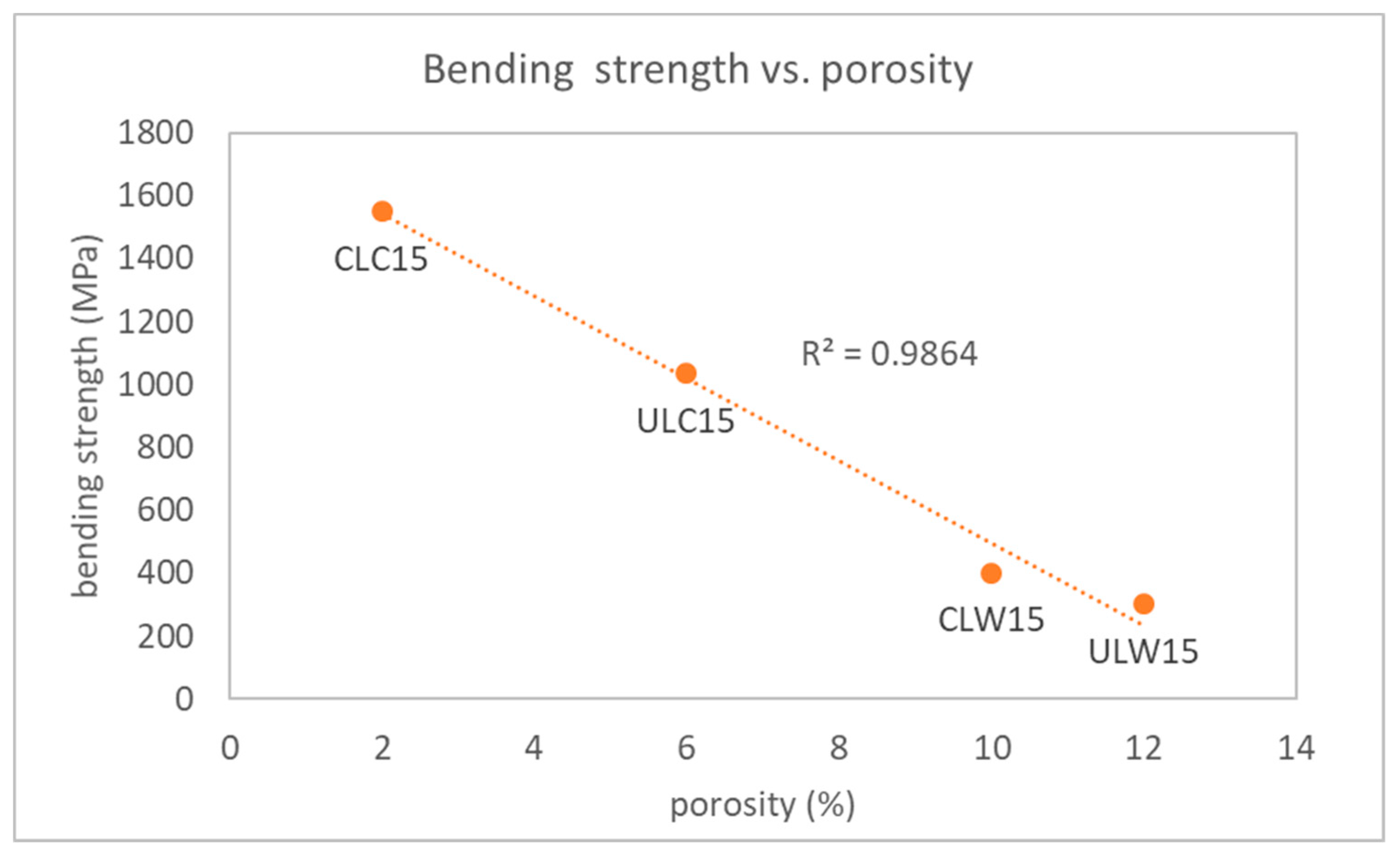
3.3. Mechanical Properties

As the chemical and structural analyses indicated a certain degree of spatial distribution of these characteristics, spatial variation of mechanical properties was investigated as well. Figure 9 shows 2D maps of microhardness of the CLC15, CLW15, ULC15 and ULW15 samples. By comparing the four graphs, several features can be identified. The CLW15 sample is the most homogeneous, followed by the ULW15 and CLC15 samples, while the ULC15 one shows the highest variation in microhardness. Both the starting powder state and the used foil have a distinct influence on the microhardness and its distribution. The samples sintered from the cleaned powder show higher uniformity, for both C and W foil. The samples sintered in C foil show a) stronger variation (higher values near the surfaces) and b) overall much higher microhardness values than those sintered in W foil. This shows that the C diffusion affects the entire sample volume, not just the near-surface region with higher C concentration. It should be noted that XRD did not indicate any presence of tungsten carbides in these samples. Typical hardness values of tungsten are around 300 HV [36]; those of reference ITER-qualified tungsten are around 400 HV [37,38]. The hardness determined in our samples sintered in the C foil is close to these values, while those sintered in the W foil show considerably lower hardness. The impurities in these samples are thought to be responsible for weaker interparticle bonding and increased porosity [9], which decreases the hardness.
Results of the three-point bending tests are summarized in Table 3. Remarkably higher bending strength is found for the samples sintered in C foil. Corresponding fracture surfaces that may explain this behavior are shown in Figure 10. The character of the fracture in W-foil samples indicates weaker bonding between the particles, as the fracture proceeded mostly along grain boundaries. Additionally, tungsten oxide particles were identified at the grain junctions (cf. Figure 3). On the other hand, fracture of the C-foil samples shows a higher share of transgranular fracture, witnessing a stronger bonding of the particles, which results in higher bending strength. Second-phase particles are generally absent on the fracture surfaces. A characteristic feature is the presence of spheroidal micropores (bubbles). These are possibly a consequence of tungsten oxide reduction by carbon, resulting in carbon oxide formation. Such a reaction should be accompanied by tungsten carbide formation [32], but its amount could be below the XRD detection limit. The C-foil samples have generally lower grain size than the W-foil ones. In both cases, the reducing powder treatment improved the strength by lowering the amount of tungsten oxide.
As samples sintered in C foil had generally lower porosity than those sintered in W foil, this has likely contributed to their higher hardness and bending strength. Quite a strong correlation between porosity and bending strength can be seen in Figure 11.

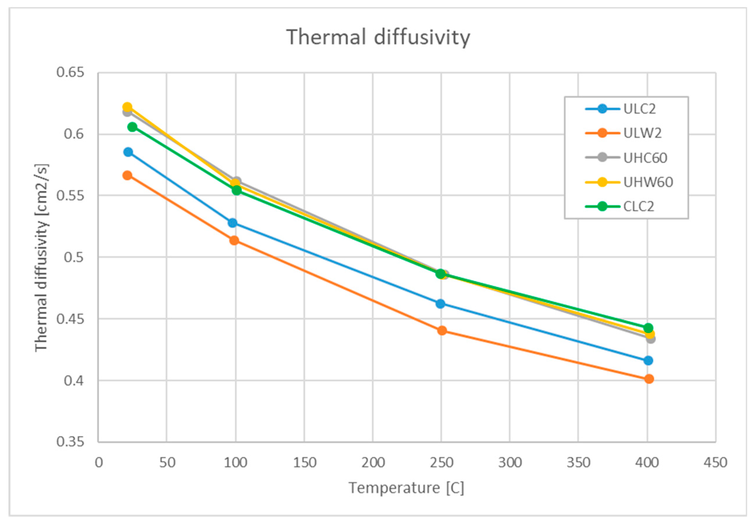
3.4. Thermal Properties

Thermal diffusivity values in the 20–400 °C range are shown in Figure 12 for the ULC2, ULW2, UHC60, UHW60 and CLC2 samples (these samples represent a subset listed in the upper half of Table 1, whose compositional analysis was shown in Figure 2, while the results from the subset listed in the lower half of Table 2 are shown in Figure 3, Figure 4, Figure 6, Figure 7, Figure 8, Figure 9, Figure 10 and Figure 11). Here, the effects of the various processing factors are not as dramatic as observed for the fracture strength. Higher diffusivity is achieved at higher sintering temperatures and longer times (UHC60 and UHW60 vs. ULC2 and ULW2), as could be expected from better bonding of the particles and reduced porosity. Although the porosity was not directly measured on these samples, such a linkage was demonstrated in Refs. [39,40]. A similar positive effect is achieved by powder treatment in the reducing atmosphere (CLC2 vs. ULC2). A rather small effect of the sintering foil is observed—UHC60 and UHW60 are practically identical, while ULC2 has only slightly higher diffusivity than ULW2. A gradual decrease of diffusivity with temperature, typical for tungsten, is seen for all samples. The highest values in this set represent ~93% (at RT) or ~88% (at 400 °C) of the values of ITER-qualified tungsten manufactured by Plansee [41].

4. Discussion

In this section, some more remarks are presented in a summarizing fashion. This study was focused on the issues of structural and chemical homogeneity and the role of oxygen and carbon impurities. Despite their small content, they were demonstrated to influence the structure and properties significantly. The presence of oxygen is attributed primarily to the surface oxidation of the fine-grained powder, which can occur even at room temperature. Additionally, it may come from air remnants adsorbed on the powder particles, which may not be completely removed during the sintering chamber evacuation. Upon sintering, the oxygen impurities tend to form tungsten oxide particles, which are found primarily at the grain boundaries and their junctions. While they may act as grain-growth inhibitors through grain-boundary pinning (similarly to other dispersion particles introduced intentionally) [12], they may also reduce the material’s ductility [33] and/or undermine high-temperature stability due to a lower melting point (~1700 °C [42]) [13]. Oxygen impurities also affect the sintering efficiency, as indicated in Refs. [9,43] and in our results, showing higher porosity in samples sintered in the W foil (Figure 13). Their amount can be effectively suppressed, although not completely eliminated, by powder pre-treatment in a reducing atmosphere. Furthermore, the interaction of oxygen impurities with carbon was observed. Based on our results and other works presented in the introduction, a possible interaction mechanism can be proposed as follows. Carbon diffuses from the graphite die and graphite foil and reduces the oxides (this is supported by the opposite trends in oxygen and carbon content in the samples showing significant gradients, and by higher carbon and lower oxygen content in samples sintered at higher temperatures, where diffusion was promoted; in Figure 2). The presence of microbubbles in the samples sintered in C foil (Figure 3a,c, Figure 10a,c) suggests the possible formation of carbon oxide (although they may have formed by entrapped air remnants). Carbon intake from the graphite foil (and/or the die) can result in the formation of a thin surface layer of tungsten carbide on the compacts at higher sintering temperatures, which could be easily removed by grinding; however, carbon effects were found throughout the entire volume of the samples (see e.g., Figure 9). Although carbon is often considered a contaminant, our results show its effects can be beneficial as well—lower porosity (Figure 8), higher strength (Table 3) and hardness (Figure 9). On the other hand, samples sintered in the C foil featured a higher degree of spatial variation (Figure 6 and Figure 9). The replacement of the C foil with a W one suppresses the inward C diffusion to some extent, resulting in samples that are more spatially homogeneous, but with higher porosity and lower strength. While the effects of the powder pre-treatment are clearly positive, those of the sintering foil are more ambiguous. Clearly, more work on the sintering optimization is desirable.

5. Conclusions

In this study, the influence of sintering conditions (such as temperature and duration), sintering environment (C or W foil) and purity of the powder on the structural and chemical homogeneity of W materials prepared by SPS was analyzed. Porosity, hardness and fracture strength are significantly affected, while thermal diffusivity rather moderately, and grain size only a little. During sintering in carbon environment, the carbon diffusion (from the graphite foil and/or die) is a significant factor. Despite spatial gradients from the surface to the inside, it affects the entire volume of the compacts. While the usage of W foil instead of C foil suppresses the inward diffusion of carbon to some extent, its effects are not beneficial in all aspects. The samples sintered in C foil show more variation of structure and properties near the surfaces; those sintered in W foil are very homogeneous. The combination of powder cleaning (annealing in a reducing atmosphere) and C foil leads to the lowest porosity, highest fracture strength and highest thermal diffusivity, which are all beneficial for the application as plasma-facing material.
The information on the spatial variation of the material characteristics (structure, composition, properties) is important for the selection of samples from the sintered compacts for specific analyses. The information on the effects of specific processing factors is useful in further optimization of the process.

Author Contributions

All authors have contributed to the research by conducting the experiments and by finalization of the manuscript. Individual contributions: J.M.: conceptualization, experiment planning, thermal diffusivity measurements, EDS, writing, M.V.: SEM, EDS, fracture strength measurements, experiment planning, J.V.: SEM, image analysis, literature survey, indentation evaluation, F.L.: XRD, J.K., P.N.: GDS, D.P., J.S.: indentation, Z.W.: IGF.

Funding

Financial support from the Czech Science Foundation though grant no. GA17-23154S is acknowledged. Part of this work was carried out within the framework of the EUROfusion Consortium and has received funding from the Euratom research and training programme 2014–2018 under grant agreement No 633053. The views and opinions expressed herein do not necessarily reflect those of the European Commission.

Conflicts of Interest

The authors declare no conflict of interest.

References

  1. Pintsuk, G. Tungsten as a Plasma-Facing Material. In Comprehensive Nuclear Materials; Konings, R.J.M., Ed.; Elsevier: Amsterdam, The Netherlands, 2012; pp. 551–581. [Google Scholar]
  2. Rieth, M.; Dudarev, S.L.; Gonzalez De Vicente, S.M.; Aktaa, J.; Ahlgren, T.; Antusch, S.; Armstrong, D.E.J.; Balden, M.; Baluc, N.; Barthe, M.F.; et al. Recent Progress in Research on Tungsten Materials for Nuclear Fusion Applications in Europe. J. Nucl. Mater. 2013, 432, 482–500. [Google Scholar] [CrossRef]
  3. Wu, Y. Manufacturing of tungsten and tungsten composites for fusion application via different routes. Tungsten 2019, 1, 80–90. [Google Scholar] [CrossRef] [Green Version]
  4. El-Atwani, O.; Hinks, J.A.; Greaves, G.; Gonderman, S.; Qiu, T.; Efe, M.; Allain, J.P. In-Situ TEM Observation of the Response of Ultrafine- and Nanocrystalline-Grained Tungsten to Extreme Irradiation Environments. Sci. Rep. 2014, 4, 4716. [Google Scholar] [CrossRef] [PubMed]
  5. Guillon, O.; Gonzalez-Julian, J.; Dargatz, B.; Kessel, T.; Schierning, G.; Räthel, J.; Herrmann, M. Field-Assisted Sintering Technology/Spark Plasma Sintering: Mechanisms, Materials, and Technology Developments. Adv. Eng. Mater. 2014, 16, 830–849. [Google Scholar] [CrossRef]
  6. Shen, Z.J.; Johnsson, M.; Zhao, Z.; Nygren, M. Spark Plasma Sintering of Alumina. J. Am. Ceram. Soc. 2002, 85, 1921–1927. [Google Scholar] [CrossRef]
  7. Minier, L.; Le Gallet, S.; Grin, Y.; Bernard, F. A Comparative Study of Nickel and Alumina Sintering Using Spark Plasma Sintering (SPS). Mater. Chem. Phys. 2012, 134, 243–253. [Google Scholar] [CrossRef]
  8. Chanthapan, S.; Kulkarni, A.; Singh, J.; Haines, C.; Kapoor, D. Sintering of Tungsten Powder with and Without Tungsten Carbide Additive by Field Assisted Sintering Technology. Int. J. Refract. Met. Hard Mater. 2012, 31, 114–120. [Google Scholar] [CrossRef]
  9. Ren, C.; Fang, Z.Z.; Zhang, H.; Koopman, M. The Study on Low Temperature Sintering of Nano-Tungsten Powders. Int. J. Refract. Met. Hard Mater. 2016, 61, 273–278. [Google Scholar] [CrossRef]
  10. Lee, G.; McKittrick, J.; Ivanov, E.; Olevsky, E.A. Densification Mechanism and Mechanical Properties of Tungsten Powder Consolidated by Spark Plasma Sintering. Int. J. Refract. Met. Hard Mater. 2016, 61, 22–29. [Google Scholar] [CrossRef]
  11. Školařová, D. Characterization of Microstructure and Mechanical Properties of Alumina Prepared by SPS Technology (in Czech). Bachelor’s Thesis, Czech Technical University, Prague, Czechia, 2014. [Google Scholar]
  12. Huang, L.; Jiang, L.; Topping, T.D.; Dai, C.; Wang, X.; Carpenter, R.; Haines, C.; Schoenung, J.M. In Situ Oxide Dispersion Strengthened Tungsten Alloys with High Compressive Strength and High Strain-to-Failure. Acta Mater. 2017, 122, 19–31. [Google Scholar] [CrossRef]
  13. Sestan, A.; Jenus, P.; Novak Krmpotic, S.; Zavasnik, J.; Ceh, M. The Role of Tungsten Phases Formation During Tungsten Metal Powder Consolidation by Fast: Implications for High-Temperature Applications. Mater. Charact. 2018, 138, 308–314. [Google Scholar] [CrossRef]
  14. Ma, J.; Zhang, J.; Liu, W.E.I.; Shen, Z. Suppressing Pore-Boundary Separation During Spark Plasma Sintering of Tungsten. J. Nucl. Mater. 2013, 438, 199–203. [Google Scholar] [CrossRef]
  15. Choi, J.; Sung, H.M.; Roh, K.B.; Hong, S.H.; Kim, G.H.; Han, H.N. Fabrication of Sintered Tungsten by Spark Plasma Sintering and Investigation of Thermal Stability. Int. J. Refract. Met. Hard Mater. 2017, 69, 164–169. [Google Scholar] [CrossRef]
  16. Vanmeensel, K.; Laptev, A.; Hennicke, J.; Vleugels, J.; Van Der Biest, O. Modelling of the Temperature Distribution During Field Assisted Sintering. Acta Mater. 2005, 53, 4379–4388. [Google Scholar] [CrossRef]
  17. Munoz, S.; Anselmi-Tamburini, U. Temperature and Stress Fields Evolution During Spark Plasma Sintering Processes. J. Mater. Sci. 2010, 45, 6528–6539. [Google Scholar] [CrossRef]
  18. Solodkyi, I.; Xie, S.S.; Zhao, T.; Borodianska, H.; Sakka, Y.; Vasylkiv, O. Synthesis of B6O Powder and Spark Plasma Sintering of B6O and B6O-B4C Ceramics. J. Ceram. Soc. Jpn. 2013, 121, 950–955. [Google Scholar] [CrossRef]
  19. Wang, P.; Yang, M.J.; Zhang, S.; Tu, R.; Goto, T.; Zhang, L.M. Suppression of Carbon Contamination in SPSed CaF2 Transparent Ceramics by Mo Foil. J. Eur. Ceram. Soc. 2017, 37, 4103–4107. [Google Scholar] [CrossRef]
  20. Biswas, P.; Chakravarty, D.; Suresh, M.B.; Johnson, R.; Mohan, M.K. Fabrication of Graphite Contamination Free Polycrystalline Transparent MgAl2O4 Spinel by Spark Plasma Sintering Using Platinum Foil. Ceram. Int. 2016, 42, 17920–17923. [Google Scholar] [CrossRef]
  21. Shongwe, M.B.; Diouf, S.; Durowoju, M.O.; Olubambi, P.A.; Ramakokovhu, M.M.; Obadele, B.A. A Comparative Study of Spark Plasma Sintering and Hybrid Spark Plasma Sintering of 93W-4.9Ni-2.1Fe Heavy Alloy. Int. J. Refract. Met. Hard Mater. 2016, 55, 16–23. [Google Scholar] [CrossRef]
  22. Dudina, D.V.; Bokhonov, B.B. Elimination of Oxide Films During Spark Plasma Sintering of Metallic Powders: A Case Study Using Partially Oxidized Nickel. Adv. Powder Technol. 2017, 28, 641–647. [Google Scholar] [CrossRef]
  23. Morita, K.; Kim, B.N.; Yoshida, H.; Hiraga, K.; Sakka, Y. Assessment of Carbon Contamination in MgAl2O4 Spinel During Spark-Plasma-Sintering (SPS) Processing. J. Ceram. Soc. Jpn. 2015, 123, 983–988. [Google Scholar] [CrossRef]
  24. Vilémová, M.; Lukáč, F.; Veverka, J.; Illková, K.; Matějíček, J. Controlling the Carbide Formation and Chromium Depletion in W-Cr Alloy During Field Assisted Sintering. Int. J. Refract. Met. Hard Mater. 2019, 79, 217–223. [Google Scholar] [CrossRef]
  25. Gludovatz, B.; Wurster, S.; Weingartner, T.; Hoffmann, A.; Pippan, R. Influence of Impurities on the Fracture Behaviour of Tungsten. Philos. Mag. 2011, 91, 3006–3020. [Google Scholar] [CrossRef]
  26. Lawrenz, D.; Mitchell, J. Thermal Evolution Methods for Carbon, Sulfur, Oxygen, Nitrogen and Hydrogen in Iron and Steel Analysis. In Encyclopedia of Analytical Chemistry; Wiley: Hoboken, NJ, USA, 2001; pp. 8991–9008. [Google Scholar]
  27. Payling, R.; Nelis, T. Glow Discharge Optical Emission Spectroscopy: A Practical Guide; Royal Society of Chemistry: London, UK, 2003. [Google Scholar]
  28. Bergman, O. Influence of Oxygen Partial Pressure in Sintering Atmosphere on Properties of Cr-Mo Prealloyed Powder Metallurgy Steel. Powder Metall. 2007, 50, 243–249. [Google Scholar] [CrossRef]
  29. Gross, E.; Dahan, D.B.; Kaplan, W.D. The Role of Carbon and Sio2 in Solid-State Sintering of Sic. J. Eur. Ceram. Soc. 2015, 35, 2001–2005. [Google Scholar] [CrossRef]
  30. Venables, D.S.; Brown, M.E. Reduction of Tungsten Oxides with Carbon. 1. Thermal Analyses. Thermochim. Acta 1996, 283, 251–264. [Google Scholar] [CrossRef]
  31. Venables, D.S.; Brown, M.E. Reduction of Tungsten Oxides with Carbon. 2. Tube Furnace Experiments. Thermochim. Acta 1996, 283, 265–276. [Google Scholar] [CrossRef]
  32. Venables, D.S.; Brown, M.E. Reduction of Tungsten Oxides with Carbon Monoxide. Thermochim. Acta 1997, 291, 131–140. [Google Scholar] [CrossRef]
  33. Davis, J.R. ASM Specialty Handbook: Heat-Resistant Materials; ASM International: Materials Park, OH, USA, 1997; p. 368. [Google Scholar]
  34. Lee, G.; Maniere, C.; McKittrick, J.; Gattuso, A.; Back, C.; Olevsky, E.A. Oxidation Effects on Spark Plasma Sintering of Molybdenum Nanopowders. J. Am. Ceram. Soc. 2019, 102, 801–812. [Google Scholar] [CrossRef]
  35. Gutin, S.S.; Panov, A.A.; Khlopin, M.I. Effect of oxide films in the sintering of aluminum powders. Sov. Powder Metall. Met. Ceram. 1972, 11, 280–282. [Google Scholar]
  36. MatWeb: Tungsten. Available online: http://www.matweb.com/search/datasheet_print.aspx?matguid=41e0851d2f3c417ba69ea0188fa570e3 (accessed on 23 July 2019).
  37. Rosas Saad, J.A. Tungsten Recrystallization Behavior Under Steady and Transient Hydrogen Plasma Loading. Master’s Thesis, Delft University of Technology, Delft, The Netherlands, 2018. [Google Scholar]
  38. Sung, H.-M. Development of Tungsten Sintering Technology for Fusion Applications. Master’s Thesis, Seoul National University, Seoul, Korea, 2017. [Google Scholar]
  39. Gelbstein, Y.; Haim, Y.; Kalabukhov, S.; Kasiyan, V.; Hartmann, S.; Rothe, S.; Frage, N. Correlation between Thermal and Electrical Properties of Spark Plasma Sintered (SPS) Porous Copper. In Sintering Techniques of Materials; Lakshmanan, A., Ed.; InTechOpen: London, UK, 2015. [Google Scholar] [Green Version]
  40. Matějíček, J.; Mušálek, R.; Dlabáček, Z.; Klevarová, V.; Kocmanová, L.; Cinert, J. Processing and Properties of Tungsten-Steel Composites and FGMs Prepared by Spark Plasma Sintering. Fusion Eng. Des. in preparation.
  41. Kanpara, S.; Khirwadkar, S.; Belsare, S.; Bhope, K.; Swamy, R.; Patil, Y.; Mokariya, P.; Patel, N.; Patel, T.; Galodiya, K. Fabrication of Tungsten & Tungsten Alloy and Its High Heat Load Testing for Fusion Applications. Mater. Today Proc. 2016, 3, 3055–3063. [Google Scholar]
  42. Wikipedia: Tungsten(IV) Oxide. Available online: https://en.wikipedia.org/wiki/Tungsten(IV)_oxide (accessed on 23 July 2019).
  43. Autissier, E.; Richou, M.; Minier, L.; Naimi, F.; Pintsuk, G.; Bernard, F. Spark plasma sintering of pure and doped tungsten as plasma facing material. Phys. Scr. 2014, 2014, T159. [Google Scholar] [CrossRef]
Figure 1. SEM images of the 0.5 µm (a) and 0.7 µm (b) powders. The powders contain even finer particles with various degrees of agglomeration, thus the nominal sizes are only approximate.
Metals 09 00879 g001
Figure 2. Through thickness carbon content (a) and oxygen content (b) in the ULW2, ULC2, UHW60, UHC60 and CLC2 samples, determined by GDS. Sample surface is on the left.
Metals 09 00879 g002
Figure 3. SEM images of fracture surfaces and corresponding O elemental maps of the CLC15 (a), CLW15 (b), ULC15 (c) and ULW15 (d) samples. Elemental maps of W and C were also acquired, but did not show notable trends, and thus, are not presented.
Metals 09 00879 g003
Figure 4. XRD pattern from a polished surface of the ULW15 sample. The most prominent peaks of the W and WO2 phases are labeled.
Metals 09 00879 g004
Figure 5. Schematic of regions within the specimens analyzed for porosity and grain size (t = near top, m = middle).
Metals 09 00879 g005
Figure 6. Representative microstructures of the CLC15 (a), CLW15 (b), ULC15 (c) and ULW15 (d) samples (top and middle regions).
Metals 09 00879 g006
Figure 7. Pore size distributions in the near-surface (2t) and central (2m) regions of the CLC15 and CLW15 samples.
Metals 09 00879 g007
Figure 8. Summary of effects of sintering foil and powder treatment on the porosity volume and grain size of the CLC15, CLW15, ULC15 and ULW15 samples.
Metals 09 00879 g008
Figure 9. 2D microhardness maps of the CLC15, CLW15, ULC15 and ULW15 samples, obtained on polished cross sections through the center of the samples. The left edges of the maps correspond to the sample circumference, right edges to the central axis.
Metals 09 00879 g009
Figure 10. Fracture surfaces of the CLC15 (a), CLW15 (b), ULC15 (c) and ULW15 (d) samples.
Metals 09 00879 g010
Figure 11. Correlation of bending strength and porosity for the CLC15, ULC15, CLW15 and ULW15 samples.
Metals 09 00879 g011
Figure 12. Temperature dependence of thermal diffusivity of the ULC2, ULW2, UHC60, UHW60 and CLC2 samples.
Metals 09 00879 g012
Figure 13. Correlation of porosity (Figure 8) with oxygen content (determined by EDS on the fracture surfaces, Table 2).
Metals 09 00879 g013
Table 1. Overview of the samples and preparation conditions. In the sample labels, the first letter designates the powder state (C = cleaned, U = uncleaned), second letter the sintering temperature (L = low, H = high), third letter the foil type (C = graphite, W = tungsten) and the number at the end the sintering time in minutes. The powder size in this table is a nominal value provided by the manufacturer; the sizes of individual grains varied, as shown in Figure 1.
LabelPowder Size (µm)Powder StateTemperature (°C)Pressure (MPa)Time (min)FoilPellet Thickness (mm)
ULC20.7 1700802C3
ULW20.7 1700802W3
UHC600.7 20007060C3
UHW600.7 20007060W3
CLC20.7cleaned1700802C2
CLW150.5cleaned17007015W3
ULW150.5 17007015W3
CLC150.5cleaned17007015C3
ULC150.5 17007015C3
Table 2. Content of carbon, oxygen and tungsten, determined by EDS, and content of WO2, determined by XRD, on the fracture surfaces (wt%).
EDSXRD
SampleCOWWO2
CLC158.51.090.50
CLW1510.41.787.81.96
ULC159.21.689.31.97
ULW159.62.288.26.16
Table 3. Bending strength of the CLC15, CLW15, ULC15 and ULW15 samples.
SampleFlexural Strength (MPa)SampleFlexural Strength (MPa)
CLC151550 ± 93CLW15402 ± 14
ULC151036 ± 70ULW15303 ± 40

