Fatigue Behaviour and Crack Initiation in CoCrFeNiMn High-Entropy Alloy Processed by Powder Metallurgy
by
 , ,
, ,
Zdeněk Chlup
1,* ,
,
Stanislava Fintová
1,
Hynek Hadraba
1,
Ivo Kuběna
1,
Monika Vilémová
2 and
Jiří Matějíček
2 1
Institute of Physics of Materials, Academy of Sciences of the Czech Republic, Zizkova 22, 616 62 Brno, Czech Republic
2
Institute of Plasma Physics, Academy of Sciences of the Czech Republic, Za Slovankou 1782/3, 182 00 Praha, Czech Republic
*
Author to whom correspondence should be addressed.
Metals 2019, 9(10), 1110; https://doi.org/10.3390/met9101110
Submission received: 24 September 2019
/
Revised: 9 October 2019
/
Accepted: 14 October 2019
/
Published: 17 October 2019
Abstract
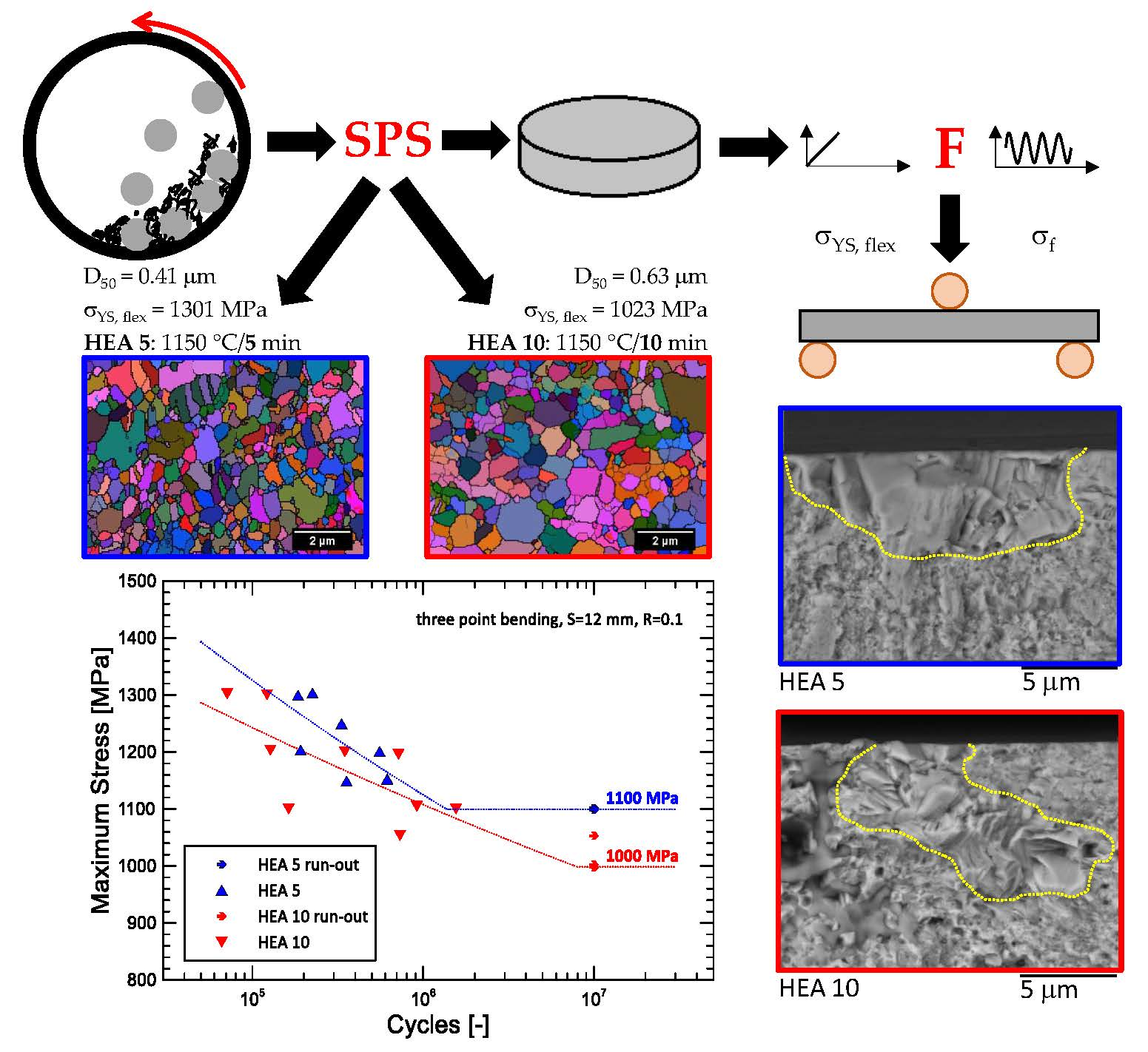
:Single-phase equiatomic five-element high entropy alloy CoCrFeMnNi was prepared by powder metallurgy. Two materials with ultra-fine-grained microstructure were prepared by spark plasma sintering (SPS) of ball-milled powder at two sintering times (5 and 10 min), assigned as HEA 5 and HEA 10, respectively. Basic microstructural and mechanical properties were evaluated. The median grain size of the microstructures was determined to be 0.4 and 0.6 μm for HEA 5 and HEA 10, respectively. The differences in the microstructure led to a significant change in strength and deformation characteristics evaluated at room temperature. The effect of cyclic loading was monitored by three-point bending fatigue test. The results show that even relatively small change in the microstructure causes a significant effect on fatigue life. The fatigue endurance limit was measured to be 1100 MPa and 1000 MPa for HEA 5 and HEA 10, respectively. The detailed fractographic analysis revealed that abnormally large grains, localised in the microstructure on the tensile loaded surface, were a typical fatigue initiation site. The formation of (nano) twins together with dislocation slips caused the crack nucleation because of the cyclic loading.

1. Introduction
High-entropy alloys are usually defined as single-phase alloys composed by at least five elements in the equiatomic composition stabilised by the configurational entropy [1,2]. However, also multiphase, non-equiatomic alloys consisting of only four elements are often referred to as HEA in the literature when some partial conditions are fulfilled [1,2,3,4]. A large variety of HEAs exists, but single-phase equiatomic five-element HEA Co-Cr-Fe-Mn-Ni, the so-called Cantor alloy, is one of the most studied [5]. The single-phase solid solution high-entropy alloys have a potential for solid solution hardening and if the single-phase fcc lattice structure is reached, a large number of slip systems ensures good ductility of the material [6,7,8,9]. Nevertheless, the experimental data about mechanical behaviour of this alloy type are still not fully understood and in some cases are controversial. The preferential processing method of this type of HEA is some variant of casting usually followed by heat treatment [5,8,9,10,11]. Also, powder metallurgy resulting in differences in the HEA microstructure as well as in the properties was used in [7,12,13,14]. The microstructure of the cast alloys is rather coarse with the grain sizes range from tens to hundreds of micrometres. On the contrary, when the powder metallurgy approach for the alloy preparation was applied, the ultra-fine-grained structure was reached. The precipitation of secondary phases (usually Cr rich phase) during the alloy preparation and processing was also described by some authors [1,6].
The tensile or compressive properties of CoCrFeMnNi alloy in the wide range of temperatures from cryogenic up to 1200 °C were studied, showing changes in the active deformation and damage mechanisms. The room temperature ultimate strength usually ranged from approx. 600 MPa [11,15,16,17] up to approx. 2 GPa [18,19] with the corresponding ductility in tenths of a percent, respectively, depending mostly on the grain size and processing route. The major active deformation mechanism at room temperature is the dislocation slip, while deformation-induced nanoscale twinning (nano twinning) is active at cryogenic temperatures, leading to a significant strain hardening [6,11,16,20]. In some cases, the (nano) twinning is connected with significant ductility of the HEA alloy at low temperatures. The creep resistance and deformation mechanisms acting at various elevated temperatures were investigated recently [21]. The addition of stabilizing dispersion or addition of elements forming secondary phases into the microstructure enhanced the creep properties of HEA significantly [22,23]. The enhancement can be ascribed to the inhibited HEA grain growth controlled by the pinning effect of the second phase particles dispersion either on the grain boundaries or on the dislocations and twins. Also, the predominant deformation mechanism is changed from dislocation glide to the diffusional creep when dispersion is present in the HEA microstructure [21,22]. The HEA response to the dynamic loading was investigated only in a few works [15,24,25,26]. High cycle fatigue data obtained on a coarse-grained HEA (average grain size of 245 μm) suggested that the fatigue endurance limit is just below the alloy tensile yield strength. Cr–Mn base oxide inclusions of the size up to 5 μm present in the microstructure were determined as the fatigue crack initiation sites and deformation twins formed during cycling and their boundaries act as the fatigue crack propagation paths in this coarse-grained alloy [15]. The effect of the grain size on the fatigue behaviour of an ultra-fine-grained CoCrFeMnNi HEA with fully recrystallized microstructure, processed by cold rolling of cast ingots and annealing was investigated by other authors in [24]. Their findings indicate that the grain refinement has a positive effect on both the applicable stress amplitude and the fatigue endurance limit even though in the ultra-fine-grained structure the cracks were present due to the material processing. The pre-existing primary cracks act as the fatigue cracks initiation sites. Detailed analysis of the dislocation structure of the ultra-fine-grained fatigue tested material showed differences in the dislocation structure evolution at two different stress amplitudes used for testing. While very limited loose dislocations were detected in the interior of some grains (most of the grains were dislocation free) for low-stress amplitudes, dislocation activity in most grains was characteristic for high-stress amplitude. However, no dislocation arrangements such as cell structure or deformation twins were observed within the grains. Authors also indicated that no grain coarsening was observed during the material fatigue testing. The absence of the dislocation cell structure was explained by the small grain size [27]. The absence of deformation twins was attributed to the raised twinning stress with grain refinement.
The present study is aimed at the characterization and identification of crack initiation mechanisms during cyclic loading of two mechanically alloyed and compacted by spark plasma sintering (SPS) CoCrFeNiMn HEAs. The SPS treatment performed at slightly different conditions resulted in different microstructure in terms of grain size influencing materials three-point bending static and fatigue properties. Fractographic analysis of the fatigue fracture surfaces revealed the same mechanism of the fatigue crack initiation for both materials, which was suggested by the observations performed by TEM on FIB foils extracted from the fatigue crack initiation sites.
2. Materials and Methods
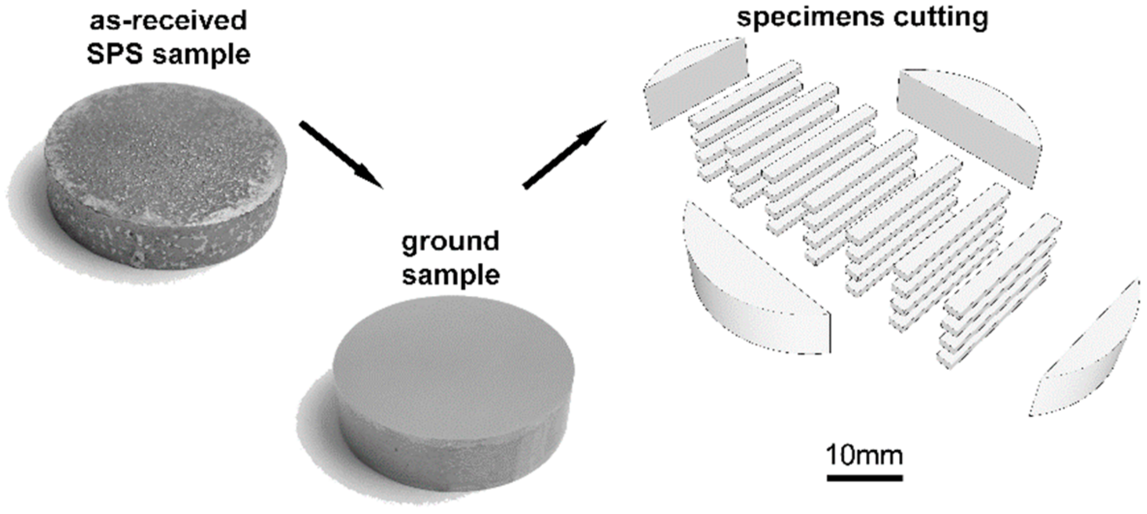
Two CoCrFeNiMn HEA alloys varying in the grain size distribution as a result of SPS compaction parameters were prepared. The alloy powder was prepared from pure powders of elements by ball milling process as described in detail elsewhere [7]. The compaction of the materials (hereafter HEA 5 and HEA 10) was conducted by the SPS technique with the consolidation temperature of 1150 °C for a dwell time of 5 and 10 min, respectively. Obtained discs were ground to regular shape (see Figure 1) and their density was determined by an Archimedes double weighting method using the ISO 18754-2013 standard. The discs were cut into the specimen shape by an electro-discharge method, see Figure 1 for the schematic cutting plan. Rectangular specimens with nominal dimensions of 2.5 × 1 × 18 mm were prepared. All specimen sides were ground and polished, finishing by 1 μm diamond paste. The specimen surface polishing was performed to allow an analysis of the signs of the localization of the cyclic plastic deformation and fatigue crack initiation sites. Elastic modulus of each material was determined using an impulse excitation technique RFDA 26 (IMCE, Genk, Belgium) from minimally three rectangular specimens and ten natural frequency readings complying with the ASTM E1876-15 standard. Vickers hardness of the compacted specimens was determined according to the EN ISO 6507 standard by means of an instrumented ZHU0.2 hardness tester (Zwick/Roell, Ulm, Germany) under a maximum load of 1 N. Three-point bending configuration with a span of 12 mm was used for static and fatigue tests performed at an Instron Elektropuls 3000 (Instron, Norwood, MA, USA) electrodynamic testing machine. Initially, static flexural tests with a crosshead speed of 0.5 mm.min−1 were realized. The flexural stress was calculated according to the general equation for the maximum stress of the beam loaded in the three-point bending mode, σ = 3FL/2b0h02, where F is the applied force, L is the supporting rollers span, b0 is the initial width and h0 the initial height of the specimen. The strain was calculated from the maximum deflection of the specimen and its initial height h0. The flexural yield and fracture characteristics were determined, see for example the ASTM E855 standard.
The same three-point bending configuration installed in the Instron Elektropuls 3000 machine as for static tests is employed for the fatigue experiments. The cyclic loading at cycle asymmetry ratio R = 0.1 with the nominal frequency of 20 Hz at ambient temperature was used. The experiments were performed under the load control mode. Fatigue endurance limit based on a minimum of three specimens not broken until reaching 1 × 10⁷ cycles was determined for each material.
The LYRA 3 XMH FEG/SEM (Tescan, Brno, Czech Republic) scanning electron microscope (SEM) was used for the analysis of the microstructure and specimen surfaces with the aim to characterize surface relief evolution because of the localization of the cyclic plastic deformation and for the fractographic analysis. For characterization of the microstructure using electron backscatter diffraction (EBSD) (Oxford Instruments, High Wycombe, UK), the grain boundaries were defined for those grain misorientations larger than 15° and analysed by Aztec software. Focused ion beam (FIB) technique was adopted to prepare TEM foils from the fatigue crack initiation sites to analyse the localization of the plastic deformation because of the cyclic loading using a JEM-2100F (Jeol, Tokyo, Japan) transmission electron microscope (TEM) in the scanning mode (STEM).
3. Results
3.1. Microstructure and Physical Properties
The basic microstructural characteristics of the prepared materials were determined and are summarized in Table 1. Density, determined by Archimedes double weighting method, shows that nearly fully dense material was obtained independently on the sintering conditions. The theoretical density of 8.01 g.cm−3 was calculated according to the real chemical composition determined by EDS. Slightly higher then nominal content of iron was detected in analysed HEAs because of the powder contamination during the milling process. The overall porosity or inclusions are expected in the material at the level of approx. 2.5 vol.%, estimated from the relative density. The commonly used median grain size D50 was determined from the EBSD data to demonstrate the differences between both microstructures later illustrated on mechanical response.
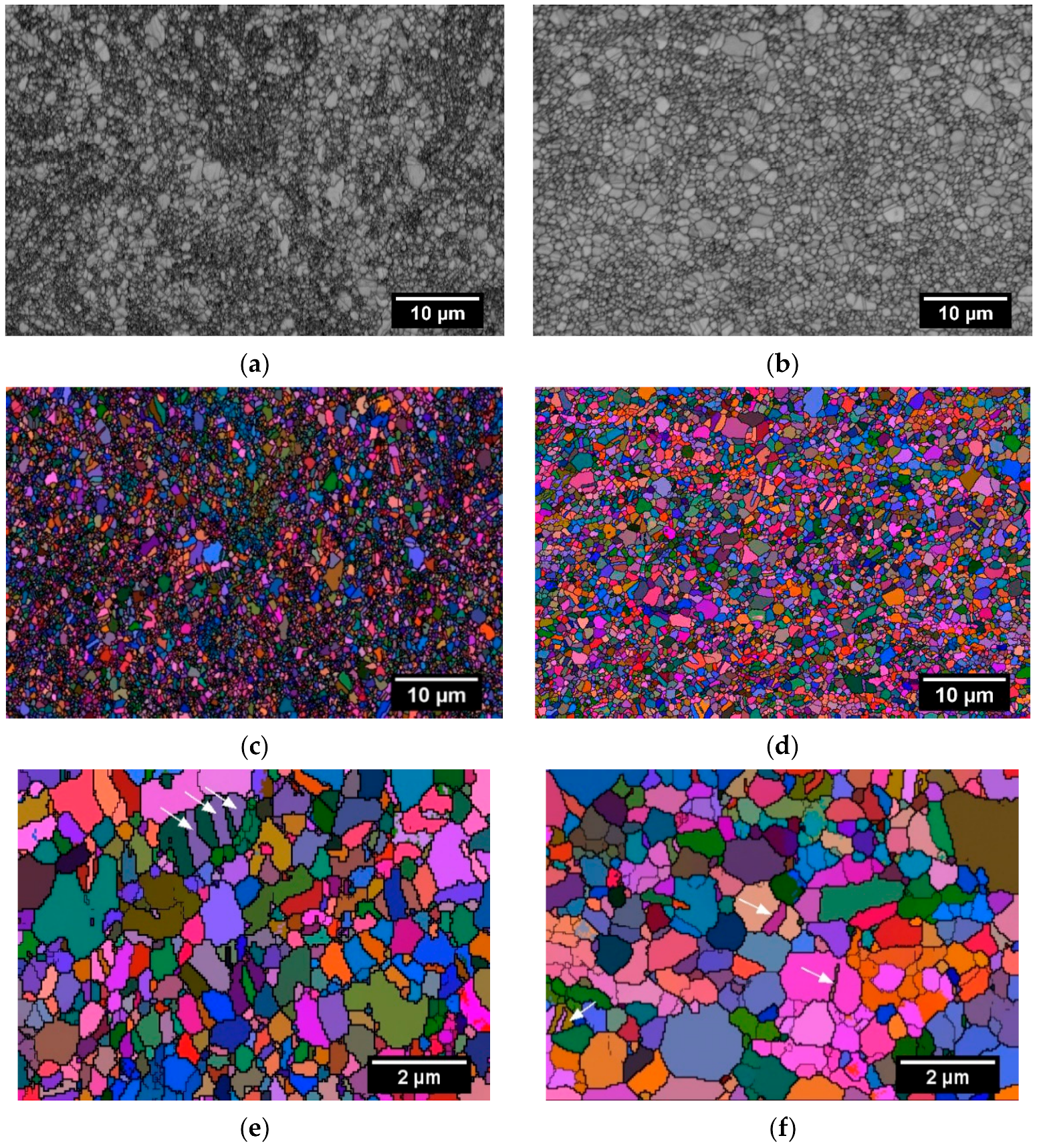
The microstructure of the processed materials is shown in Figure 2. The EBSD technique displayed in Euler angles mode for the microstructure characterization was used. Both materials have a characteristic ultra-fine-grained structure, Figure 2. Finer grain size can be observed in the case of HEA 5 when compared to the HEA 10 alloy. However, some grain size abnormalities (i.e., presence of large grains over a few micrometres) can be observed for both the material states. In details of the obtained microstructures, the local presence of twins can be seen, Figure 2e,f marked by arrows.
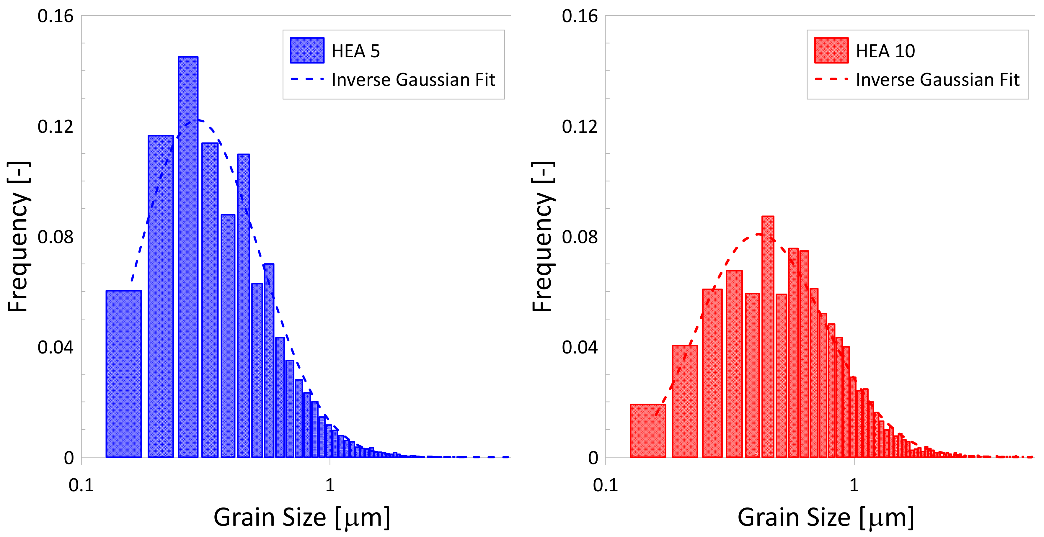
The slight bimodality represented by the presence of few abnormally large grains in the grain size distribution obtained from more than 4000 grains is represented by histograms shown in Figure 3. The mixture of sub-micron and over-micron grains was observed for both the material states. The number of grains larger than 2 μm was 1% for HEA 5 and 2% for HEA 10 which result in approximately 45 vol.% in both cases. Prolongation of the SPS treatment dwells time from 5 min for HEA 5 to 10 min for HEA 10 resulted in grain growth of the material. The inverse Gaussian fitting (characteristic by Dgauss location and Dgauss scale parameter) was applied to distinguish the differences in the grain size distributions, see Table 1.
3.2. Quasi-Static Mechanical Properties
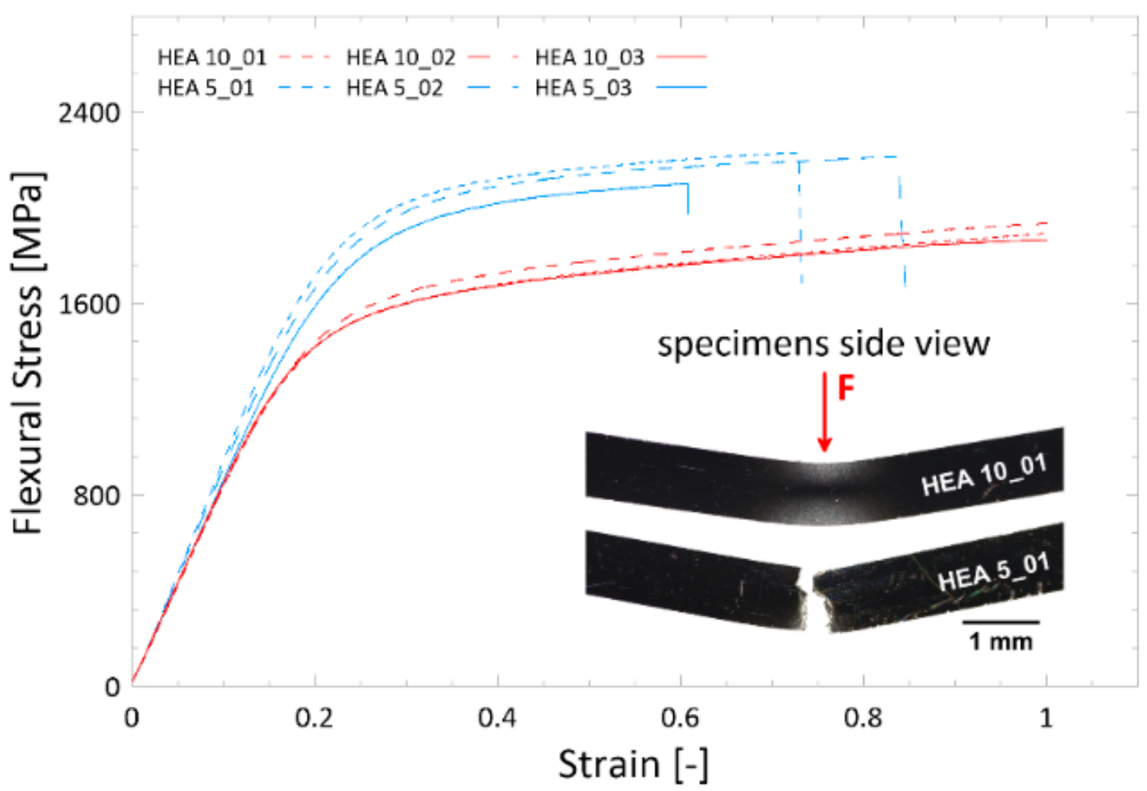
A higher value of the flexural stress for the HEA 5 when compared to the HEA 10 was measured, see Figure 4. The elongation at fracture of both the material states could not be determined. While the HEA 5 specimens reached the failure during the bending tests, the HEA 10 specimens remained only bent without any sign of (micro) cracking on the tensile loaded surface (see insert in Figure 4 showing specimens after loading). In the case of HEA 5 specimens, the final fracture occurred after strain reaching only 60 to 80% of the flexural strain in all cases. The loading traces of three-point bending tests are shown in Figure 4 and results are summarized in Table 2.
Elastic modulus determined by an impulse excitation technique on the bending bars for both material states has similar values, Table 2.
3.3. Fatigue Properties and Fatigue Crack Initiation
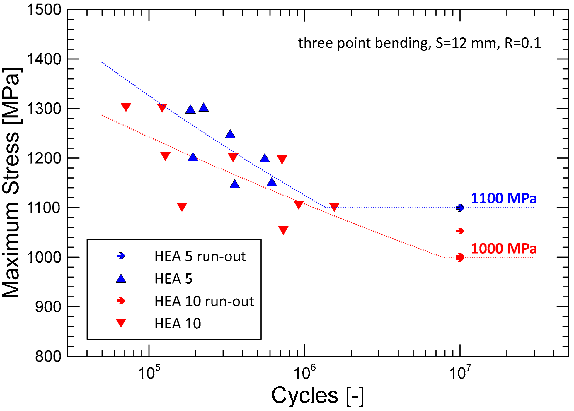
The cyclic behaviour determined by the three-point bending configuration with asymmetry parameter R = 0.1 is represented by S-N curves in Figure 5. The fatigue endurance limit (given by unbroken specimens so-called run-outs) is marked by arrows in the graph (Figure 5). A higher fatigue endurance limit at 1 × 10⁷ cycles was determined for HEA 5 when compared to the HEA 10. The fatigue endurance limit σf was determined to be 1100 MPa and 1000 MPa for HEA 5 and HEA 10, respectively. The difference of 100 MPa (10%) corresponds to the difference between the yield strength determined from the quasi-static flexural tests (Figure 4) and materials microstructure. However, only a slight difference in the reached number of cycles to the fracture at individual stress amplitude levels was observed between the HEA 10 and HEA 5 specimens.
4. Discussion
The mechanical alloying accompanied by the compaction using SPS method led to the homogenous and dense material in both cases of processing time. The resulting microstructure is ultra-fine-grained, submicron on average, when compared with the CoCrFeNiMn HEAs prepared by other methods where the grain size is usually few orders of magnitude larger [11,26,28]. It was demonstrated that Cantors alloy can be refined by post heat treatment to obtain similar microstructure as investigated [24]. However, the processing history can influence the resulting behaviour of the material [18]. Differences in mechanical response observed for investigated materials shown in Figure 4 correlate with the material grain size including the slight structure bimodality. HEA 5 having smaller grain size (0.4 μm) from the examined material states reached higher strength properties, however, an occurrence of the final fracture after relatively small plastic deformation was characteristic for all the tested specimens of this material. Mainly the grain boundary strengthening (caused by dislocations blocking at the grain boundaries) was more pronounced in the case of the material state with finer grains. Other strengthening mechanisms as precipitation hardening are considered to have a similar effect for both materials [29]. The limited ability of the dislocation slip and/or twinning in the small grains deteriorates plastic deformation of the material, and cleavage fracture was characteristic for the quasi-statically loaded specimens. In accordance with those findings the HEA 10, exhibiting slightly larger grain size (0.6 μm), reached lower flexural strength properties, approximately 30% drop in the flexural yield strength, however, achieved higher deformability compared to the HEA 5. The slip activity in combination with twinning could be more pronounced in the material state with larger grain size resulting in the ability of the material to resist the bending loading without specimen’s failure. The twin induced plasticity together with lower initial dislocation densities in larger grains seems to be crucial [29,30].
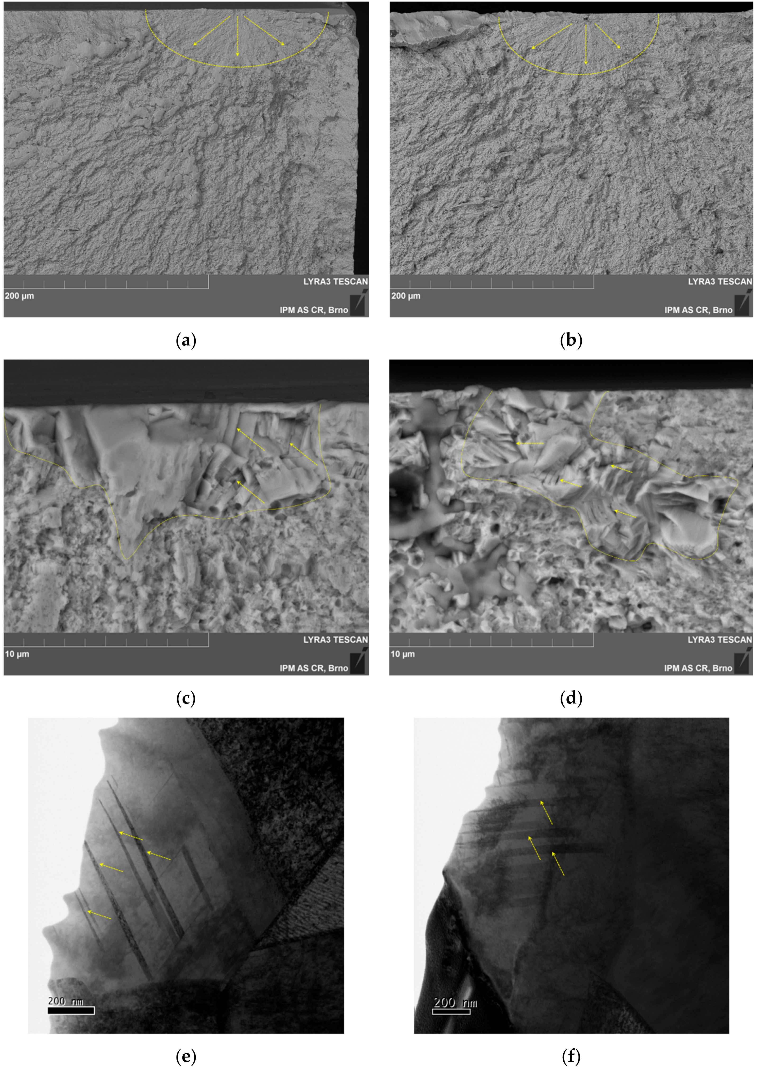
Fatigue experiments revealed that the measurable difference in the estimated fatigue endurance limit correlates with the grain size and grain size distribution of the prepared materials–the material with smaller grain size and less pronounced grain size distribution bimodality (HEA 5) reached higher fatigue endurance limit. The S-N curve was shifted to the higher number of cycles to the fracture for HEA 5 with smaller grain size; however, a significant data scatter was characteristic for both material states. The obtained scatter of the reached number of cycles to the fracture at the same maximum stress was shown to be given by the observed fatigue crack initiation mechanism and the presence of abnormally large grains, respectively. Fractographic analysis of the broken specimens showed that the crack initiation sites were always located in the highly tensile-loaded large grains (usually located just below or at the surface), as can be seen in Figure 6a–d. The dashed line shows the area of crack initiation typical for powder materials, and arrows determine the crack propagation from the initiation place. This behaviour was observed to be typical for both material states. Large grains with microcracks (see Figure 6c,d where large grains are emphasised by dashed line and selected microcracks are indicated by arrows) exhibiting character following the twin′s boundaries were observed in the fatigue crack initiation sites. Also, authors in [15] observed the twins acting as the fatigue crack propagation paths. No detectable influence of the specimen geometry (rectangular cross-section) on the fatigue crack initiation was observed. No crack initiation from the specimen edge was observed. As was reported by some authors the deformation by twining mechanism is activated at higher levels of macroscopic deformations when critical twining stress can be reached [17,29,30]. As the mechanism responsible for the specimens fatigue failure, a local stress concentration and microcracks formation because of the localized extensive slip activity and formation of twins in the abnormally large grains can be assumed. Microcracks nucleated at twin-grain boundaries act as initial defects and new stress concentrators, see Figure 6c,d. Localisation of the cyclic plastic deformation on stress concentration sites results in fatigue cracks initiation and growth. In the present microstructure, only the larger grains have a sufficient volume allowing dislocation and crystallographic defects motion during the cyclic loading. The surface and subsurface fatigue crack initiation was observed in all tested specimens. The localization of the cyclic plastic deformation and evolution of the (nano) twins in randomly situated large grains can be also indicative for the fatigue data scatter (i.e., randomly distributed larger grains serving as suitable crack initiation sites can be located not only at the maximum of the stress field but also out of the loading pin or below the outer surface).
Lamellae for the TEM analysis extracted in the close vicinity of the fatigue crack initiation sites were prepared by FIB. The TEM analysis revealed a characteristic feature–nano-size twins–within the large grains of both materials structure, see Figure 6e,f where selected twins are marked by arrows. The small size of the (nano) twins compared to the twins observed by EBSD in the material before cyclic deformation indicates that the (nano) twins were formed because of the cyclic loading. The observation is in agreement with other works [10,15] where the authors reported the formation of (nano) twins at higher strains. Authors in [15] observed twins with an average thickness of 100 nm created because of the tensile stress state in the case of homogenized coarse-grained state (grain size of 291.3 μm) of cast CoCrFeMnNi HEA after cycling loading. Different results were obtained by other authors when ultra-fine-grained HEA was explored. They reported a strong dislocation activity with no twinning under cyclic loading [24]. This can also be the supporting findings of this work where only larger grains were subjected to the extensive (nano) twinning and dislocation slip as is documented in Figure 6e,f. The crack initiation mechanism is therefore different when compared with coarse grain microstructure or refined one having narrow grain size distribution without abnormally large grains as reported by some authors [24,26]. The localization of plastic deformation to the conveniently situated in the abnormally large grain results in the formation of micro-cracks within the grain followed by final brittle fracture without any typical sign of fatigue crack propagation.
5. Conclusions
Three-point bending static and fatigue properties of the powder metallurgy prepared and SPS processed CoCrFeNiMn HEA alloys were examined. The experimentally obtained data were discussed in terms of fractographic analysis and TEM observations focused on the fatigue crack initiation mechanism. Based on the experimental results, the following conclusions can be drawn.
Increase of the SPS processing time from 5 to 10 min at the temperature of 1150 °C influenced the material grain size. The larger grain size was observed for the material processed for a longer time, a slight structural bimodality was characteristic for both material states.
HEA alloy with smaller grain size reached higher values of the flexural strength; however, specimen failure was a characteristic for this material after deformation reaching only 60–80%. The material state with the larger grain size reached lower strength properties, however, no specimen failure during the three-point bending test occurred.
Higher fatigue endurance limit and slightly better fatigue properties were reached with the material with smaller grain size. A large scatter of measured data was characteristic for both material states.
Microcracks formed in large grains of the microstructure were due to the (nano) twins acting as the fatigue crack initiation sites for both material states.
For both HEAs, the fatigue life was controlled by the presence of large grains that acted as the fatigue crack initiation sites.
Author Contributions
Conceptualization, Z.C. and H.H.; data curation, S.F.; funding acquisition, H.H.; investigation, Z.C., S.F., H.H., I.K., M.V., and J.M.; methodology, Z.C. and S.F.; validation, I.K. and M.V.; writing–original draft, Z.C.; writing—review and editing, S.F., H.H., I.K., M.V., and J.M.
Funding
This research was funded by the Czech Science Foundation project No. 17-23964S.
Conflicts of Interest
The authors declare no conflict of interest.
Nomenclature
| Symbol | Unit | Description |
| D50 | μm | Median grain size |
| Dgauss location | μm | Inverse Gaussian Fit–location parameter |
| Dgauss scale | μm | Inverse Gaussian Fit–scale parameter |
| Eavg, IET | GPa | Elastic modulus by impulse excitation technique (IET) in flexural mode |
| HV0.1 | GPa | Vickers hardness at a load of 100g/0.981N |
| R | - | Fatigue stress ratio σmin/σmax |
| S | mm | The span at three-point bending |
| σmax | MPa | The maximum stress level of the fatigue cycle |
| σmin | MPa | The minimum stress level of the fatigue cycle |
| εfr | - | Strain at fracture |
| ρ | g.cm−3 | Measured density |
| ρrel | % | Relative density |
| ρtheor | g.cm−3 | Theoretical density |
| σf | MPa | Fatigue endurance limit (fatigue strength) |
| σfr, flex | MPa | Flexural fracture stress |
| σYS, flex | MPa | Flexural yield strength at 0.2% of plastic strain |
References
- Gao, M.C.; Yeh, J.-W.; Liaw, P.K.; Zhang, Y. High-Entropy Alloys; Springer International Publishing: Cham, Switzerland, 2016. [Google Scholar]
- Miracle, D.B.; Senkov, O.N. A critical review of high entropy alloys and related concepts. Acta Mater. 2017, 122, 448–511. [Google Scholar] [CrossRef] [Green Version]
- Niendorf, T.; Wegener, T.; Li, Z.; Raabe, D. Unexpected cyclic Stress-Strain response of Dual-Phase High-Entropy alloys induced by partial reversibility of deformation. Scr. Mater. 2018, 143, 63–67. [Google Scholar] [CrossRef]
- He, F.; Wang, Z.; Wu, Q.; Li, J.; Wang, J.; Liu, C.T. Phase separation of metastable CoCrFeNi high entropy alloy at intermediate temperatures. Scr. Mater. 2017, 126, 15–19. [Google Scholar] [CrossRef]
- Cantor, B.; Chang, I.T.H.; Knight, P.; Vincent, A.J.B. Microstructural development in equiatomic multicomponent alloys. Mater. Sci. Eng. A 2004, 375–377, 213–218. [Google Scholar] [CrossRef]
- Klimova, M.V.; Shaysultanov, D.G.; Zherebtsov, S.V.; Stepanov, N.D. Effect of second phase particles on mechanical properties and grain growth in a CoCrFeMnNi high entropy alloy. Mater. Sci. Eng. A 2019, 748, 228–235. [Google Scholar] [CrossRef]
- Hadraba, H.; Chlup, Z.; Dlouhy, A.; Dobes, F.; Roupcova, P.; Vilemova, M.; Matejicek, J. Oxide dispersion strengthened CoCrFeNiMn High-Entropy alloy. Mater. Sci. Eng. A-Struct. Mater. Prop. Microstruct. Process. 2017, 689, 252–256. [Google Scholar] [CrossRef]
- Li, J.; Gao, B.; Wang, Y.; Chen, X.; Xin, Y.; Tang, S.; Liu, B.; Liu, Y.; Song, M. Microstructures and mechanical properties of nano carbides reinforced CoCrFeMnNi high entropy alloys. J. Alloy. Compd. 2019, 792, 170–179. [Google Scholar] [CrossRef]
- Qin, G.; Chen, R.; Zheng, H.; Fang, H.; Wang, L.; Su, Y.; Guo, J.; Fu, H. Strengthening FCC-CoCrFeMnNi high entropy alloys by Mo addition. J. Mater. Sci. Technol. 2019, 35, 578–583. [Google Scholar] [CrossRef]
- Ma, X.; Chen, J.; Wang, X.; Xu, Y.; Xue, Y. Microstructure and mechanical properties of cold drawing CoCrFeMnNi high entropy alloy. J. Alloy. Compd. 2019, 795, 45–53. [Google Scholar] [CrossRef]
- Otto, F.; Dlouhý, A.; Somsen, C.; Bei, H.; Eggeler, G.; George, E.P. The influences of temperature and microstructure on the tensile properties of a CoCrFeMnNi High-Entropy alloy. Acta Mater. 2013, 61, 5743–5755. [Google Scholar] [CrossRef]
- Vaidya, M.; Anupam, A.; Bharadwaj, J.V.; Srivastava, C.; Murty, B.S. Grain growth kinetics in CoCrFeNi and CoCrFeMnNi high entropy alloys processed by spark plasma sintering. J. Alloy. Compd. 2019, 791, 1114–1121. [Google Scholar] [CrossRef]
- Gao, X.; Lu, Y. Laser 3D printing of CoCrFeMnNi high-entropy alloy. Mater. Lett. 2019, 236, 77–80. [Google Scholar] [CrossRef]
- Laurent-Brocq, M.; Goujon, P.A.; Monnier, J.; Villeroy, B.; Perrière, L.; Pirès, R.; Garcin, G. Microstructure and mechanical properties of a CoCrFeMnNi high entropy alloy processed by milling and spark plasma sintering. J. Alloy. Compd. 2019, 780, 856–865. [Google Scholar] [CrossRef]
- Kim, Y.-K.; Ham, G.-S.; Kim, H.S.; Lee, K.-A. High-Cycle fatigue and tensile deformation behaviors of Coarse-Grained equiatomic CoCrFeMnNi high entropy alloy and unexpected hardening behavior during cyclic loading. Intermetallics 2019, 111, 106486. [Google Scholar] [CrossRef]
- Gali, A.; George, E.P. Tensile properties of High- and Medium-Entropy alloys. Intermetallics 2013, 39, 74–78. [Google Scholar] [CrossRef]
- Laplanche, G.; Bonneville, J.; Varvenne, C.; Curtin, W.A.; George, E.P. Thermal activation parameters of plastic flow reveal deformation mechanisms in the CrMnFeCoNi High-Entropy alloy. Acta Mater. 2018, 143, 257–264. [Google Scholar] [CrossRef]
- Bae, J.W.; Moon, J.; Jang, M.J.; Yim, D.; Kim, D.; Lee, S.; Kim, H.S. Trade-off between tensile property and formability by partial recrystallization of CrMnFeCoNi High-Entropy alloy. Mater. Sci. Eng. A 2017, 703, 324–330. [Google Scholar] [CrossRef]
- Schuh, B.; Pippan, R.; Hohenwarter, A. Tailoring bimodal grain size structures in nanocrystalline compositionally complex alloys to improve ductility. Mater. Sci. Eng. A 2019, 748, 379–385. [Google Scholar] [CrossRef]
- Sun, S.J.; Tian, Y.Z.; An, X.H.; Lin, H.R.; Wang, J.W.; Zhang, Z.F. Ultrahigh cryogenic strength and exceptional ductility in ultrafine-grained CoCrFeMnNi High-Entropy alloy with fully recrystallized structure. Mater. Today Nano 2018, 4, 46–53. [Google Scholar] [CrossRef]
- Kang, Y.B.; Shim, S.H.; Lee, K.H.; Hong, S.I. Dislocation creep behavior of CoCrFeMnNi high entropy alloy at intermediate temperatures. Mater. Res. Lett. 2018, 6, 689–695. [Google Scholar] [CrossRef]
- Dobes, F.; Hadraba, H.; Chlup, Z.; Dlouhy, A.; Vilemova, M.; Matejicek, J. Compressive creep behavior of an Oxide-Dispersion-Strengthened CoCrFeMnNi high-entropy alloy. Mater. Sci. Eng. A Struct. Mater. Prop. Microstruct. Process. 2018, 732, 99–104. [Google Scholar] [CrossRef]
- Tsao, T.-K.; Yeh, A.-C.; Kuo, C.-M.; Kakehi, K.; Murakami, H.; Yeh, J.-W.; Jian, S.-R. The High Temperature Tensile and Creep Behaviors of High Entropy Superalloy. Sci. Rep. 2017, 7, 12658. [Google Scholar] [CrossRef] [PubMed]
- Tian, Y.Z.; Sun, S.J.; Lin, H.R.; Zhang, Z.F. Fatigue behavior of CoCrFeMnNi High-Entropy alloy under fully reversed cyclic deformation. J. Mater. Sci. Technol. 2019, 35, 334–340. [Google Scholar] [CrossRef]
- Li, W.; Wang, G.; Wu, S.; Liaw, P.K. Creep, fatigue, and fracture behavior of High-Entropy alloys. J. Mater. Res. 2018, 33, 3011–3034. [Google Scholar] [CrossRef]
- Kashaev, N.; Ventzke, V.; Petrov, N.; Horstmann, M.; Zherebtsov, S.; Shaysultanov, D.; Sanin, V.; Stepanov, N. Fatigue behaviour of a laser beam welded CoCrFeNiMn-Type high entropy alloy. Mater. Sci. Eng. A 2019, 766, 138358. [Google Scholar] [CrossRef]
- Holste, C. Cyclic plasticity of nickel, from single crystals to submicrocrystalline polycrystals. Philos. Mag. 2004, 84, 299–315. [Google Scholar] [CrossRef]
- Schuh, B.; Mendez-Martin, F.; Völker, B.; George, E.P.; Clemens, H.; Pippan, R.; Hohenwarter, A. Mechanical properties, microstructure and thermal stability of a nanocrystalline CoCrFeMnNi high-entropy alloy after severe plastic deformation. Acta Mater. 2015, 96, 258–268. [Google Scholar] [CrossRef] [Green Version]
- Haase, C.; Barrales-Mora, L.A. Influence of deformation and annealing twinning on the microstructure and texture evolution of Face-Centered cubic High-Entropy alloys. Acta Mater. 2018, 150, 88–103. [Google Scholar] [CrossRef]
- Li, W.; Long, X.; Huang, S.; Fang, Q.; Jiang, C. Elevated fatigue crack growth resistance of Mo alloyed CoCrFeNi high entropy alloys. Eng. Fract. Mech. 2019, 218, 106579. [Google Scholar] [CrossRef]
Figure 1.
Schematic of the preparation of the specimen from as-sintered spark plasma sintering (SPS) disk.
Figure 1.
Schematic of the preparation of the specimen from as-sintered spark plasma sintering (SPS) disk.

Figure 2.
The microstructure of experimental materials from the EBSD analysis displayed in band contrast (a,b) and Euler’s colours (c–f), twins in the microstructure are marked by arrows.
Figure 2.
The microstructure of experimental materials from the EBSD analysis displayed in band contrast (a,b) and Euler’s colours (c–f), twins in the microstructure are marked by arrows.

Figure 3.
Grain size distribution in the log-normal scale for HEA 5 and HEA 10 with fitted inverse Gaussian distribution shown by dashed line.
Figure 3.
Grain size distribution in the log-normal scale for HEA 5 and HEA 10 with fitted inverse Gaussian distribution shown by dashed line.

Figure 4.
Stress–strain loading curves from three-point bending tests and detail photographs of the side view of specimens in the vicinity of the loading roller after test demonstrating the extent of plastic deformation without fracture for HEA 10 and fractured HEA 5.
Figure 4.
Stress–strain loading curves from three-point bending tests and detail photographs of the side view of specimens in the vicinity of the loading roller after test demonstrating the extent of plastic deformation without fracture for HEA 10 and fractured HEA 5.

Figure 5.
S-N curves of the experimental material states.

Figure 6.
Fatigue crack initiation sites and deformation structure near the fracture initiation sites. (a) Fatigue crack initiation site is marked by dashed line and arrows, HEA 5, SEM, BSE; (b) fatigue crack initiation site is marked by dashed line and arrows, HEA 10, SEM, BSE; (c) detail of initiation site, HEA 5, SEM, BSE, the large grain(s) are marked by the dashed line, arrows indicate microcracks; (d) detail of initiation site, HEA 10, SEM, BSE, the large grain(s) are marked by the dashed line, arrows indicate microcracks; (e) fatigue crack initiation site in HEA 5, STEM, bright field, selected nano-size twins are indicated by arrows; (f) fatigue crack initiation site in HEA 10, STEM, bright field, selected nano-size twins are indicated by arrows.


Table 1.
Microstructural characteristics of examined HEAs.
| Material | ρ | ρrel | D50 | Dgauss Location | Dgauss Scale |
|---|---|---|---|---|---|
| g.cm−3 | % | μm | μm | μm | |
| HEA 5 | 7.821 ± 0.001 | 97.7 | 0.407 | 0.485 | 1.364 |
| HEA 10 | 7.799 ± 0.001 | 97.4 | 0.628 | 0.726 | 1.833 |
Note: The scatter is characterized by ± Standard Deviation to the average values.
Table 2.
Mechanical properties of examined HEAs.
| Material | Eavg,IET | σYS,Flex | σfr,Flex | εfr | σf | HV0.1 |
|---|---|---|---|---|---|---|
| GPa | Mpa | MPa | - | MPa | GPa | |
| HEA 5 | 205.4 ± 1.7 | 1301 ± 21 | 2177 ± 68 | 0.72 ± 0.11 | 1100 | 3.95 ± 0.06 |
| HEA 10 | 206.8 ± 1.0 | 1023 ± 6 | N/A | N/A | 1000 | 3.67 ± 0.15 |
Note: The scatter is characterized by ± standard deviation to the average values.
© 2019 by the authors. Licensee MDPI, Basel, Switzerland. This article is an open access article distributed under the terms and conditions of the Creative Commons Attribution (CC BY) license (http://creativecommons.org/licenses/by/4.0/).
Share and Cite
MDPI and ACS Style
Chlup, Z.; Fintová, S.; Hadraba, H.; Kuběna, I.; Vilémová, M.; Matějíček, J. Fatigue Behaviour and Crack Initiation in CoCrFeNiMn High-Entropy Alloy Processed by Powder Metallurgy. Metals 2019, 9, 1110. https://doi.org/10.3390/met9101110
AMA Style
Chlup Z, Fintová S, Hadraba H, Kuběna I, Vilémová M, Matějíček J. Fatigue Behaviour and Crack Initiation in CoCrFeNiMn High-Entropy Alloy Processed by Powder Metallurgy. Metals. 2019; 9(10):1110. https://doi.org/10.3390/met9101110
Chicago/Turabian StyleChlup, Zdeněk, Stanislava Fintová, Hynek Hadraba, Ivo Kuběna, Monika Vilémová, and Jiří Matějíček. 2019. "Fatigue Behaviour and Crack Initiation in CoCrFeNiMn High-Entropy Alloy Processed by Powder Metallurgy" Metals 9, no. 10: 1110. https://doi.org/10.3390/met9101110
Note that from the first issue of 2016, this journal uses article numbers instead of page numbers. See further details here.