
The Effect of Temperature and Phase Shift on the Thermomechanical Fatigue of Nickel-Based Superalloy


Institute of Physics of Materials, Czech Academy of Sciences, Žižkova 22, 616 00 Brno, Czech Republic
*
Author to whom correspondence should be addressed.
Metals 2022, 12(6), 993; https://doi.org/10.3390/met12060993
Submission received: 21 May 2022
/
Revised: 2 June 2022
/
Accepted: 6 June 2022
/
Published: 10 June 2022
(This article belongs to the Special Issue Mechanical Behavior of Metallic Materials under Different Loading Conditions)
Abstract
:In this paper, the minimum temperature and phase shift effects on the thermo–mechanical fatigue (TMF) behavior of Inconel 713LC are investigated. TMF tests were performed under 0° (in-phase-IP) and +180° (out-of-phase-OP) phase shifts between mechanical strain and temperature. Cylindrical specimens were cycled at constant mechanical strain amplitude with a strain ratio of Rε = −1. Tests were performed with temperature ranges of 300–900 °C and 500–900 °C. The heating and cooling rate was 5 °C/s. Fatigue hardening/softening curves and fatigue life data were assessed. Results show that out-of-phase loading was less damaging than in-phase loading. Scanning electron microscopy (SEM) examination of metallographic sections indicated that the life-reducing damage mechanism was intergranular cavitation under in-phase loading. Transmission electron microscopy (TEM) revealed honeycomb structures for IP loading. The plastic strain localization into persistent slip bands was typical for OP loading. For out-of-phase loading, fatigue damage appeared to be dominant. The increase in the temperature range led to a significant decrease in fatigue life. The reduction of fatigue life was far more pronounced for out-of-phase loading. This can be ascribed to the accelerated crack propagation at high tensile stress under out-of-phase loading as well as the amount of accommodated plastic strain deformation. Based on the SEM scrutiny of metallographic sections and TEM observations of dislocation arrangement, the prevailing damage mechanisms were documented and the lifetime behavior was accordingly discussed.
1. Introduction
Nickel-based superalloys are typically employed for gas turbine wheel components in jet propulsion and energy production [1]. These components are often subjected to high variable stresses at elevated temperatures in a harsh environment, where a combination of fatigue, creep, and oxidation can cause premature failure [2]. The harshest loading conditions are those where strain or stress vary simultaneously with temperature, i.e., in the case of thermomechanical fatigue (TMF). Since the inlet temperature of hot gases during service is still well above the melting point of superalloys, turbine wheel components are thus actively cooled [3] and protected with thermal barrier coatings [4,5,6]. Consequently, noticeable temperature gradients within the component during steady-state operation occur, and together with periodical shut-down and start-up periods of power and propulsion facilities cause severe thermal expansion and contraction that are often reinforced by mechanical stresses or strains associated with centrifugal forces as turbine speed changes. This complex loading history inevitably leads to TMF failure [7]. Several papers were devoted to the TMF behavior of single crystal [8,9] and polycrystal [10,11,12] nickel-based superalloys. Guth et al. [10] studied the effect of phase shifts on the second-generation superalloy MAR-M247 in the temperature range of 100–850 °C. Results showed that the 0° phase shift between temperature and mechanical strain had the shortest life, followed by the +180° phase shift and the ±90° phase shift. Yamazaki et al. [13] found that in the case of the +180° cycle, the fatigue crack growth rate and thus fatigue life was strongly dependent on the TMF testing temperature.
For the purpose of this study, the first-generation superalloy Inconel 713LC was chosen due to its unique combination of mechanical properties and favorable production costs. It possesses an excellent capability to resist high-temperature creep [14], low cycle fatigue [5,6,15], and high cycle fatigue [16,17]. These properties are balanced by outstanding fracture toughness, which is particularly important at lower temperatures since the power units are periodically shut-down. However, TMF data of Inconel 713 and its low carbon version Inconel 713LC are rare [18]. In the present paper, the TMF behavior of the polycrystalline nickel-based superalloy Inconel 713LC is reported. This study provides a direct comparison of both the TMF load cycle and the effect of the temperature range. It also provides additional information regarding isothermal fatigue at the peak temperature of the TMF cycle. The mechanisms that account for the different lifetimes are described with particular emphasis on the two parameters investigated. The main aim is to better understand the effect of the temperature and phase shift on the lifetime and damage mechanisms. Fatigue hardening/softening curves and maximal and minimal stress evolution curves were plotted. The prevailing damage mechanism explaining the TMF lifetime differences was investigated via scanning electron microscopy (SEM) and transmission electron microscopy (TEM).
2. Materials and Methods
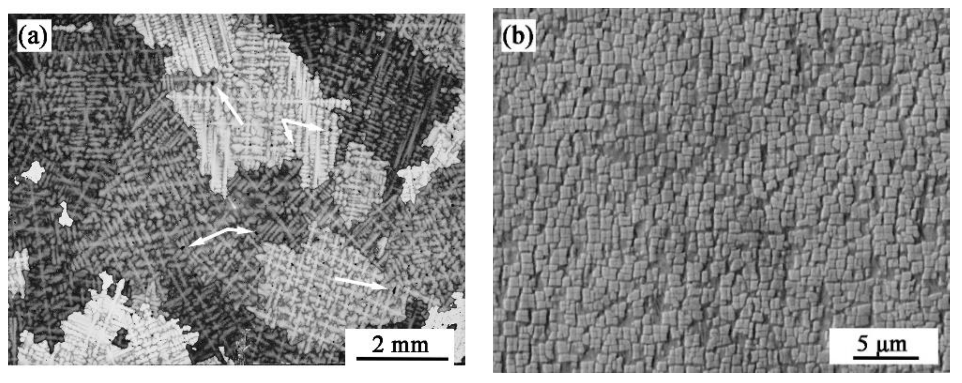
In the current study, rods prepared via an investment-casting technique with a shape close to the TMF test specimens were used. The nickel-based superalloy Inconel 713LC with the nominal chemical composition (wt. %) of 0.06 C, 11.70 Cr, 4.29 Mo, 6.02 Al, 0.64 Ti, 0.16 Ta, 0.23 Fe, 0.008 B, 2.06 Nb, 0.06 Zr, and Ni bal. was supplied by PBS Velká Bíteš a.s., Czech Republic (Velká Bíteš, CZ). Inconel 713LC is typical with coarse dendritic grains (see Figure 1a). The average grain size of the used melt is (2.18 ± 0.78) mm. The microstructure is composed of a face-centered cubic (fcc) γ matrix with a high volume of fcc γ’ strengthening precipitates, γ/γ′ eutectics, carbides, and casting defects with a size up to 150 µm. The coherent γ′ precipitates having a cuboidal shape are shown in Figure 1b.
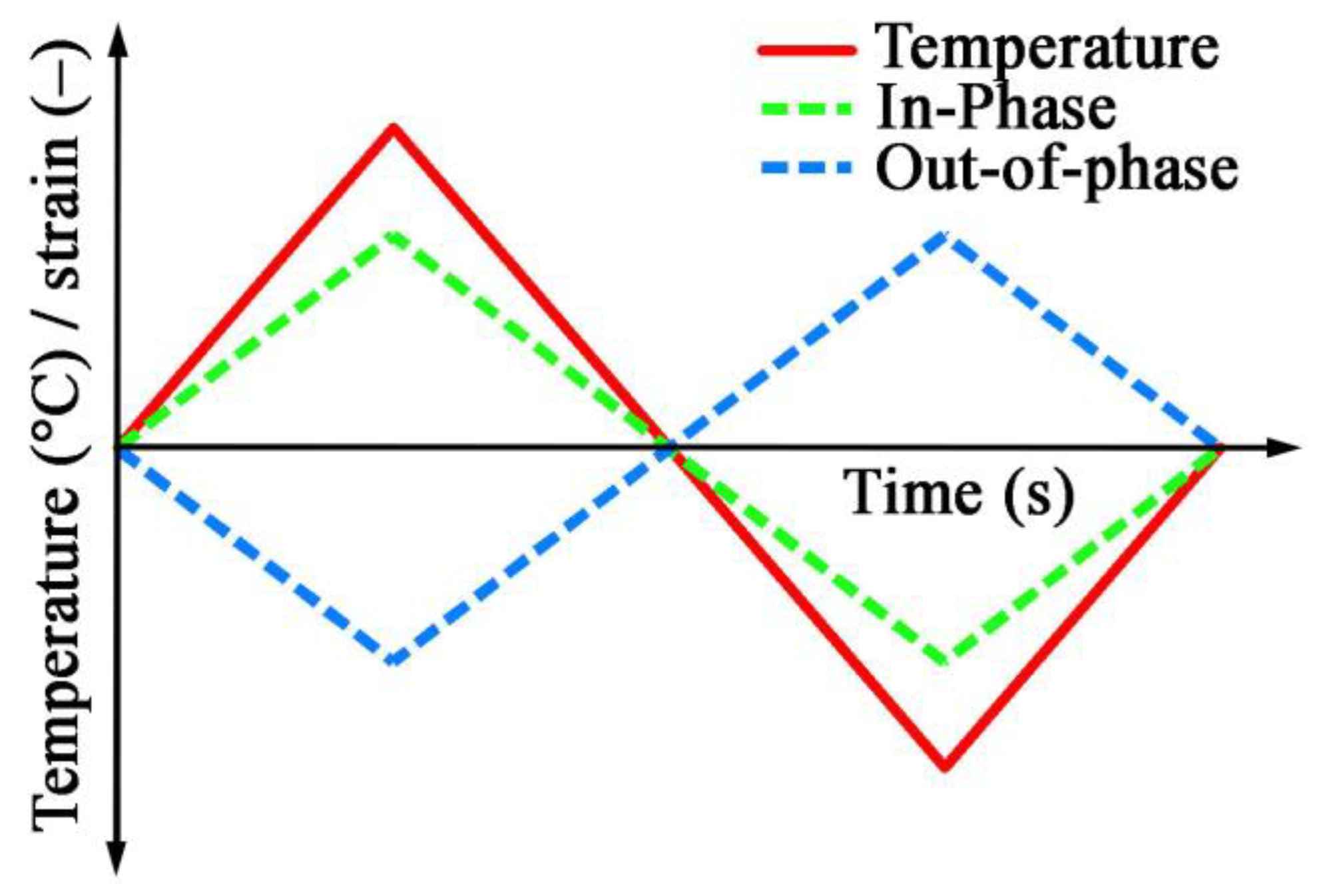
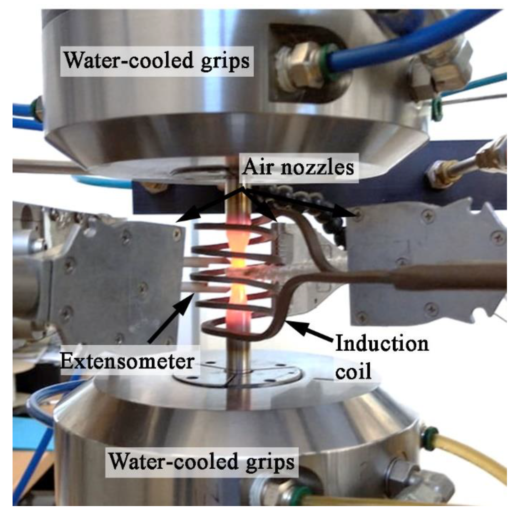
Cylindrical specimens (see Figure 2) with a diameter and gauge length of 7 mm and 16 mm, respectively, were subjected to TMF loading. Two different loading cycles were applied: in-phase (IP-TMF) and out-of-phase (OP-TMF). Figure 3 shows schematically the temperature and mechanical strain courses for these two cycles. TMF experiments were carried out in computer-controlled servo-hydraulic mechanical testing MTS 880 system (MTS Systems Corporation, Eden Prairie, MN, USA) with water-cooled hydraulic grips. Symmetric cyclic straining () with triangular shape waveform in total strain amplitude control mode was applied. The temperature was monitored and controlled by a K-type thermocouple wreathed over the specimen amid the specimen gauge length and covered by heat-resistant fabric. Heating provided a high-frequency inductive heating generator TruHeat HF 3010 (TRUMPF Hüttinger GmbH + Co. KG, Freiburg, Germany). Cooling of the specimens was achieved using the water-cooled grips along with the external airflow system. A capacitive 632.41C-11 extensometer (MTS Systems Corporation, Eden Prairie, MN, USA) equipped with 120-mm-long ceramic tips and a 12 mm base was used to control and measure the strain. The experimental setup is shown in Figure 4. The temperature was varied in two intervals: from 300 °C to 900 °C and from 500 °C to 900 °C. The cycle time was fixed to 240 s and 160 s for the 300–900 °C and 500–900 °C intervals, respectively, which corresponds to the rate of temperature change of 5 °C/s. Since the heating and cooling rate was kept constant, the strain rate differed in dependence on the applied mechanical strain amplitude. The calculated strain rate was in the range of 5 × 10⁻⁵ s−1 to 1 × 10⁻⁴ s−1 for the temperature interval of 500–900 °C and 3.3 × 10⁻⁵ s−1 to 5.8 × 10⁻⁵ s−1 for the temperature interval of 300–900 °C. This change in the strain rate is small, and it is not expected to make any significant difference in the overall behavior. The mechanical strain was determined and controlled as the total strain minus the thermal strain, which was determined for each specimen by measurement of the coefficient of thermal expansion. A code of practice for TMF tests was followed [19].
Experimental data were recorded by the Testsuit program (MTS Systems Corporation, Eden Prairie, MN, USA). A geometric series containing a total of 20 hysteresis loops per decade was chosen for recording. The stress amplitude was evaluated from the recorded hysteresis loops. The plastic strain amplitude was assessed offline from the half of the width of the hysteresis loop.
A Tescan Lyra3 XMU SEM (TESCAN ORSAY HOLDING, Brno, Czech Republic)-equipped Oxford Symmetry electron backscatter diffraction (EBSD) detector (Oxford Instruments, High Wycombe, UK) was adopted to investigate fatigue crack initiation and the propagation mechanism. The internal damage and its relation to fatigue crack propagation were studied on longitudinal metallographic sections of fatigued samples. The dislocation arrangement of Inconel 713LC was also characterized by a high-resolution transmission electron microscope (TEM) JEOL JEM-2100F (JEOL Ltd., Tokyo, Japan) with a field emission gun electron source equipped with a bright field (BF) detector for observation in scanning mode (STEM).
3. Results and Discussion
Figure 5 shows a comparison of the stress response of Inconel 713LC to the applied mechanical strain of 0.35% for IP and OP types of loading and both temperature ranges. For the sake of clarity, only one mechanical strain amplitude (0.35%) was chosen representing the overall behavior of Inconel 713LC under TMF loading. The fatigue hardening/softening curves in the representation of stress amplitude σa versus the number of elapsed cycles N are shown in Figure 4a. A stable stress response is typical for both IP and OP cycles in the temperature range of 500–900 °C, suggesting that hardening mechanisms such as the formation of new dislocations, dislocation–dislocation interactions, as well as dislocation–obstacle interactions are in balance with softening mechanisms such as the annihilation of dislocations, the reduction of the effective size of γ´ precipitates by shearing, and rafting of γ´ precipitates [1,20]. An increase in the temperature range by lowering Tmin from 500 °C to 300 °C was manifested by a shift of the stress amplitude to higher values, which can be mainly attributed to higher values of Young’s modulus at 300 °C (189 GPa) compared to 500 °C (178 GPa). This increased the absolute values of the tensile peak stress (OP) or compressive peak stress (IP) of the TMF cycle (Figure 5b). Considerable fatigue hardening can also be seen while testing in the temperature range of 300–900 °C, indicating the superiority of the above-mentioned hardening mechanisms in this particular temperature range.
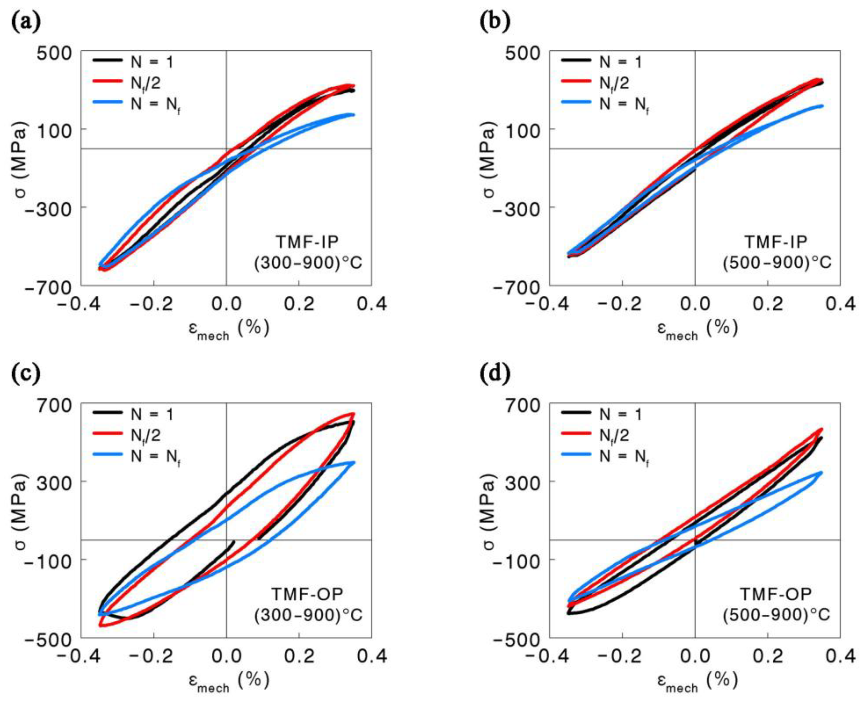
The representative stress–strain hysteresis loops for all TMF loading conditions are shown in Figure 6. The selected hysteresis loops represent the first, Nf/2, and Nf loading cycles for a mechanical strain amplitude of 0.35%. In accordance with the hardening/softening curves (Figure 5), a cyclic hardening/softening of the Inconel 713LC superalloy can be observed here as a change in the height and width of the hysteresis loop. Contrary to strain-controlled isothermal fatigue tests [20,21], the hysteresis loops under TMF loading are asymmetrical due to a temperature change. The mean stress then depends on the temperature range as well as on the shift between temperature and applied mechanical strain. When the phase shift is 180° (OP cycle), the hysteresis loop shifts towards tensile stresses and positive mean stress develops. The opposite is true for the IP cycle (0° phase shift) when the compressive mean stress develops.
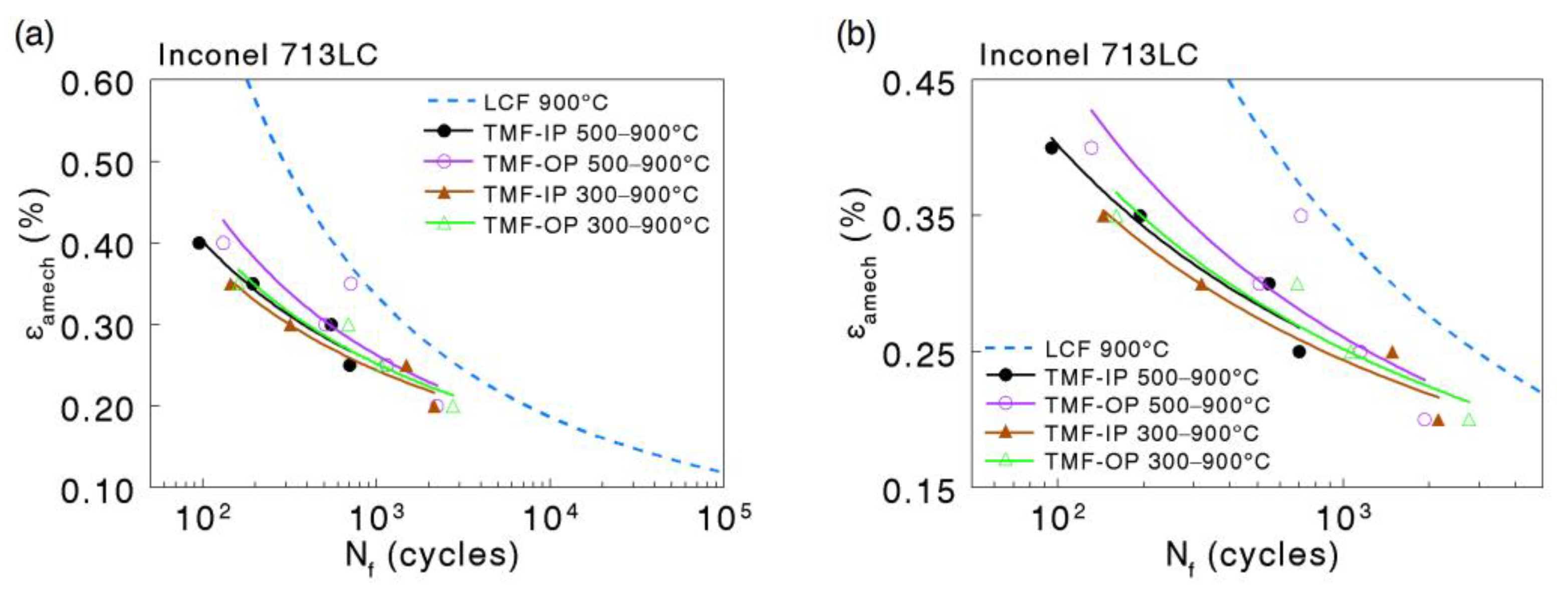
The diagram of total strain amplitude on the linear ordinate versus the number of cycles to failure on logarithmic abscissa is plotted in Figure 7. Regardless of the temperature range, OP loading revealed a slightly longer fatigue life in the entire range of strain amplitudes compared to IP loading. This behavior was also reported for other fcc metals [10,22,23]. Shifting the minimum temperature from 500 °C to 300 °C resulted in a reduction in fatigue life in both TMF cycles, which can be attributed to the higher values of plastic strain (Figure 6), which is a determining factor in fatigue [20]. Figure 7 also includes the results obtained by Šulák et al. [6] for Inconel 713LC tested under isothermal low cycle fatigue conditions at 900 °C (blue dashed curve). It is clear that TMF straining leads to a significant reduction in fatigue life, showing the importance of these experiments to ensure the safe-life of high-temperature components.
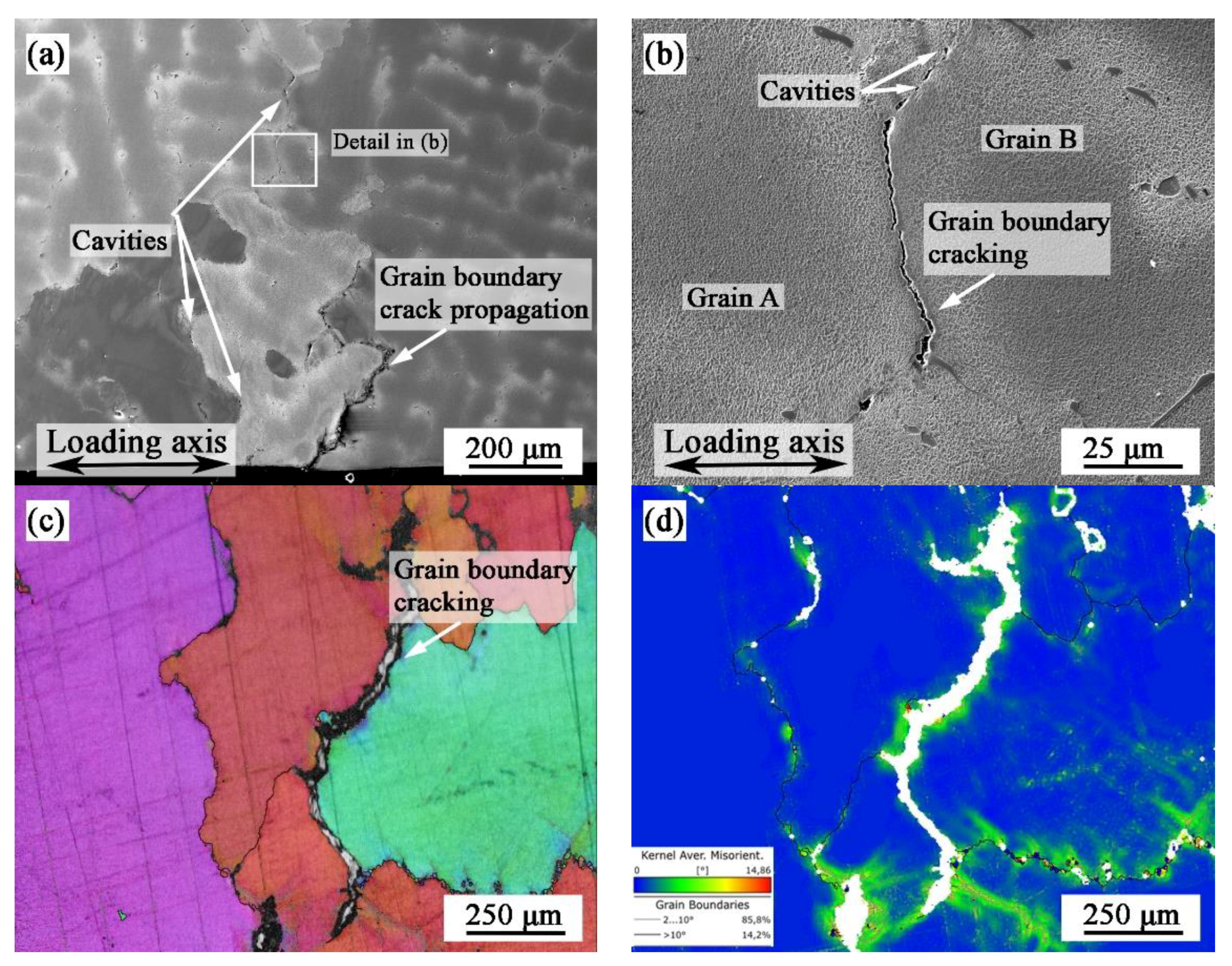
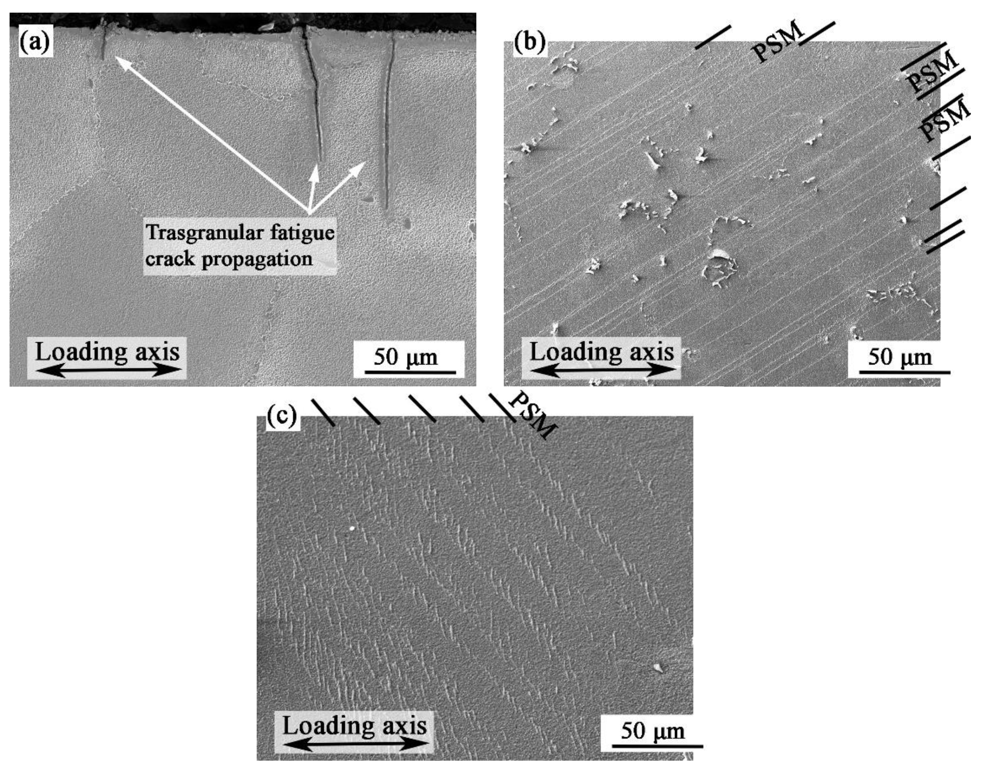
Authors have built on the SEM inspection of metallographic sections to reveal that the dominant failure mechanism changes with the phase shift. Figure 8 and Figure 9 depict typical fatigue cracks occurring under TMF loading. Regardless of the TMF conditions, fatigue cracks nucleated from the surface. However, the crack initiation site and fatigue crack propagation mechanisms differ. Fatigue crack initiations at grain boundaries and subsequent propagation of fatigue cracks along grain boundaries are typical for IP loading, as shown in Figure 8a. We can characterize this grain boundary degradation as being rooted in the migration and coalescence of vacancies and a consequential formation of cavities associated with creep damage [14,15,18,24]. Linking of fatigue cracks with internal cavities, as shown in Figure 8b, may accelerate the propagation rate and can explain the lower fatigue life observed for IP loading (Figure 7) although OP loading resulted in considerably higher maximum tensile stress (Figure 5) and higher amplitude of plastic strain (Figure 6) [12]. In addition to surface initiation at grain boundaries, internal degradation with no connection to the surface was observed for IP loading as well (Figure 8c). The inner crack was formed by the coalescence of several cavities and propagated directly along the grain boundary. The Kernel average misorientation (KAM) map showing a local grain misorientation derived from EBSD data is depicted in Figure 8d. In the vicinity of a crack (or a larger cavity), misorientation of adjacent grains occurred due to large plastic deformation ahead of a crack tip. This led to a local increase in stress which may contribute to easier crack propagation along the grain boundary. Figure 9 shows several shallow transgranular fatigue cracks typical for OP loading conditions. No evidence of creep damage under OP TMF loading was found. Zauter et al. [25] stated that when the maximum temperature of the TMF cycle lies within the creep range, creep-induced lifetime reduction occurs only in IP cycling and can be explained by a change in the fracture mode from transgranular to intergranular in OP cycling and IP, respectively. This corresponds well with the findings in this study. Furthermore, surface relief formed in the gauge length of specimens loaded under the OP TMF loading (Figure 8b,c). These structures, called persistent slip markings (PSMs), form along the active slip system, which is most often the -type plane in fcc materials [21,26,27,28]. PSMs consist of local surface elevations (extrusions) and depressions (intrusions) and form along the intersection of dislocation-rich bands (persistent slip bands—PSBs) with the surface as a consequence of localized cyclic plastic strain in PSBs. When the activity of PSBs is high enough, they arise on free surfaces and form a hill-and-valley relief on the originally flat surface and are often the cause of fatigue crack initiation in the low cycle fatigue domain [29,30,31,32]. With an increase in temperature, the PSMs oxidize heavily and their appearance changes [21]. This is associated with a change in the localization of plastic deformation, where at higher temperatures, the plastic deformation is mainly transmitted through γ matrix channels. The change in the temperature range in the case of OP TMF cycling resulted in different PSMs (compare Figure 8b,c). The wavy nature of the PSMs on the specimen cycled in the temperature range of 500–900 °C (Figure 9c) resembled PSMs, where plastic deformation is expected to occur in the matrix channels. An increase in the temperature range (300–900 °C) showed long and narrow PSMs, suggesting that precipitate shearing was dominant [27].
The number of secondary fatigue cracks after IP loading was generally lower than that after OP loading, suggesting a higher tendency for plastic strain localization, which corresponds well with the observed hysteresis loops (Figure 6). In contrast, a high number of sharp, straight, and shallow fatigue cracks, as shown in Figure 9, is characteristic of OP loading [10]. These cracks are significant stress concentrators and are extremely dangerous, especially with a decrease in temperature. In the connection with higher maximal tensile stress, sharp fatigue cracks may contribute to a reduction in fatigue life under OP loading in the temperature range of (300–900) °C (see Figure 7).
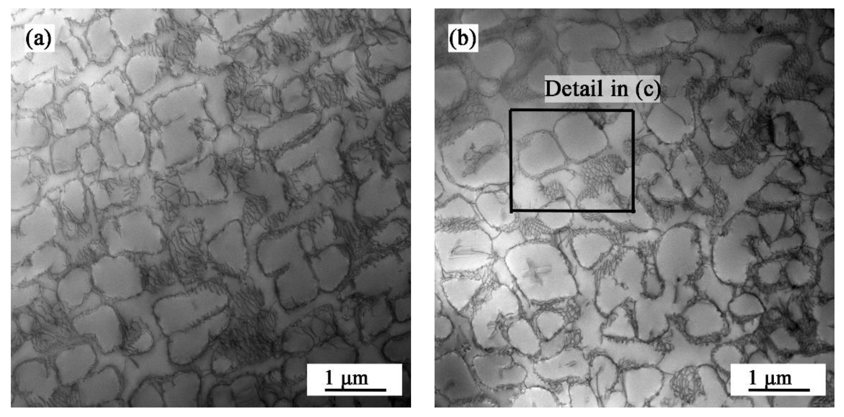
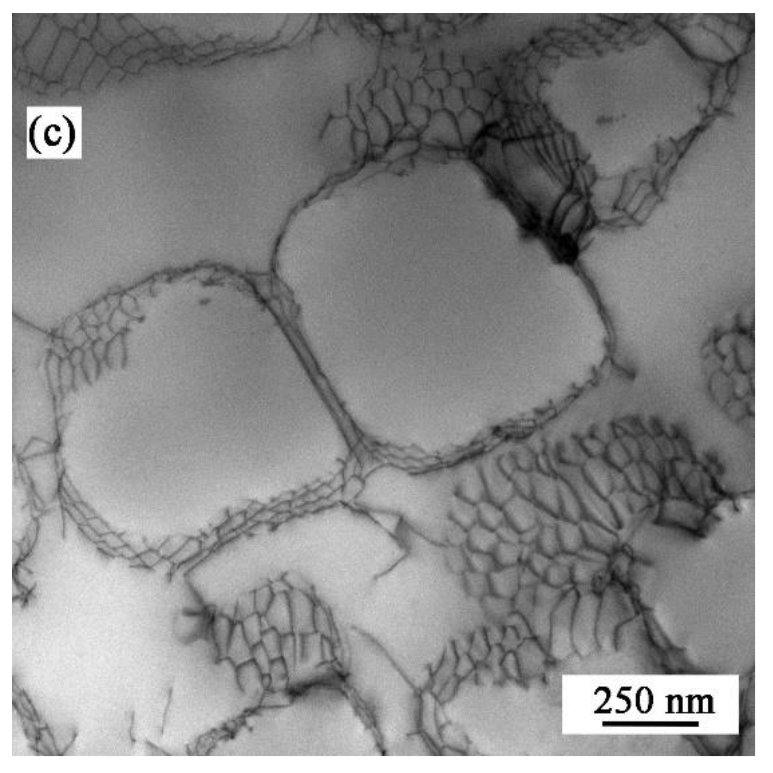
A TEM study was carried out on fractured specimens to investigate the dislocation structure. The STEM bright field images of the dislocation structure after IP TMF loading are presented in Figure 10. A dislocation arrangement and the morphology of γ′ precipitates of a specimen cyclically strained with a mechanical strain amplitude of εamech = 0.30% in the temperature range of 300–900 °C are visible in Figure 10a. The corners of γ′ particles are slightly rounded. The dislocations are restricted mainly to the γ phase and γ/γ′ interfaces. Figure 10b shows the STEM image from the specimen tested in the temperature range of 500–900 °C with the same mechanical strain amplitude (0.30%). The dislocation density does not seem to be different. However, the dislocation networks with honey-comb morphology characteristic for creep or dwell-fatigue loading [15,33] can be seen (Figure 10c).
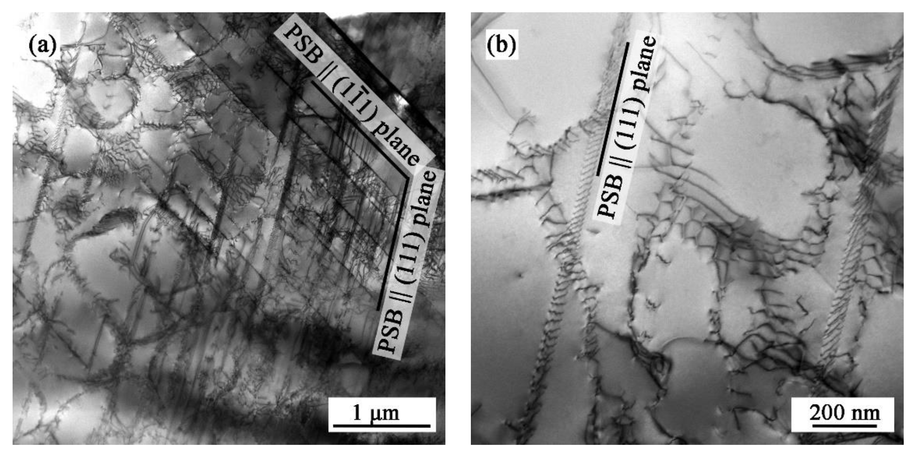
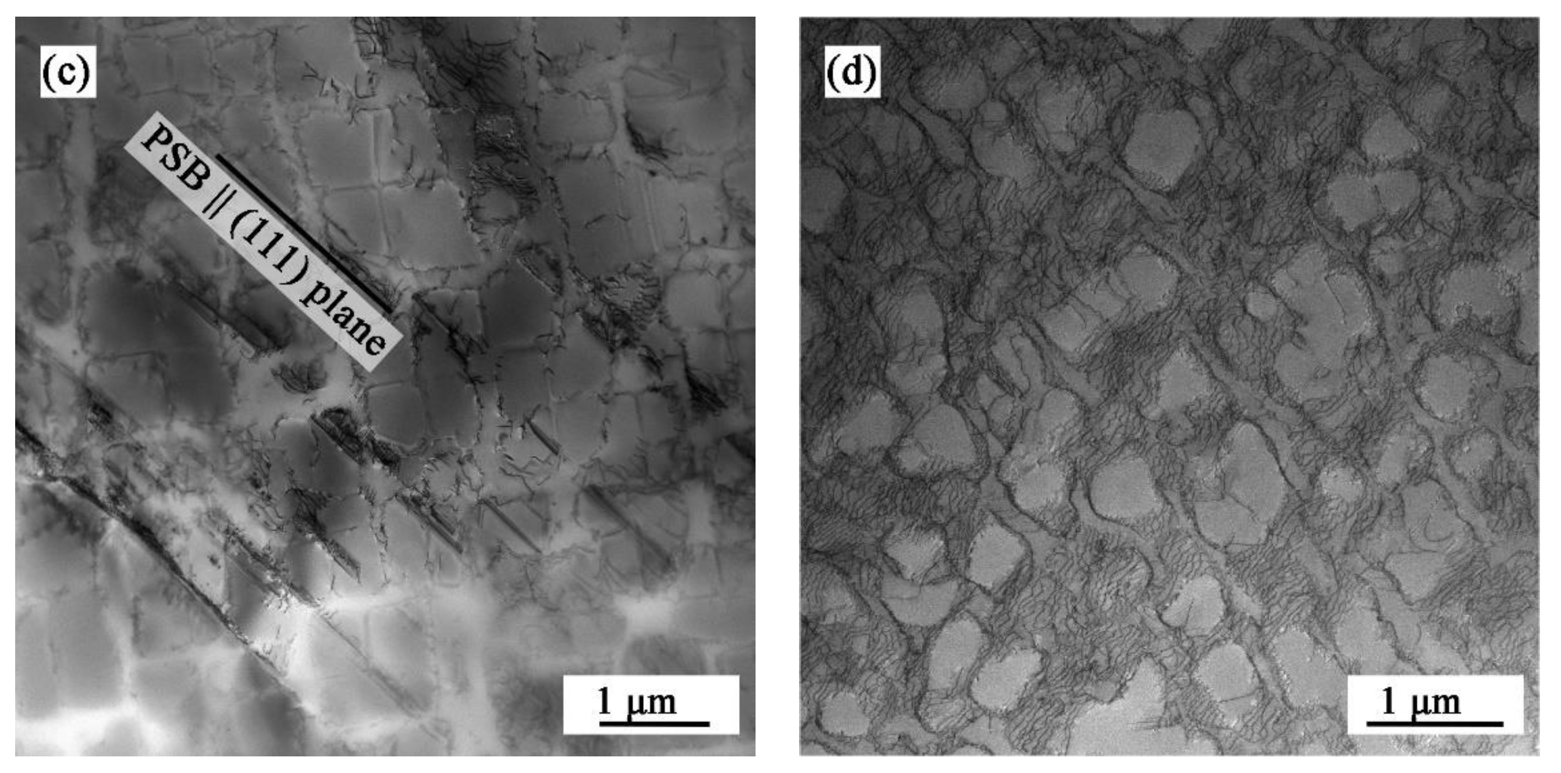
The dislocation arrangement in specimens cyclically loaded with a mechanical strain amplitude of εamech = 0.30% under OP loading conditions can be found in Figure 10. Contrary to IP TMF loading conditions where interfacial dislocations and clusters of dislocations preferably located in the γ matrix are present, under OP TMF loading, PSBs parallel to slip planes developed [34]. Figure 11a presents PSBs in the form of dislocation-rich slabs for OP TMF loading in the temperature range of 300–900 °C. A detailed view of a dislocation pile-up within PBS parallel to the slip plane is presented in Figure 11b. These slip bands cut both the γ matrix and the γ′ precipitates. Observed PSBs are different from the typical ladder-like PSBs observed for pure copper [35]. The narrowing of the temperature range (from 300–900 °C to 500–900 °C) decreased the density of PSBs (as shown in Figure 10c), which corresponds to a lower accumulation of plastic deformation in the material (Figure 5) [20,27]. In another grain (Figure 11d), the arrangement of dislocations was different. The dislocations, similar to the IP stress cycle, are mainly distributed in the channels of the γ matrix. Nonetheless, the dislocation density here is much higher than in the IP cycling (compare with Figure 10). Thus, we can conclude that a higher dislocation density in the γ matrix channels may, in effect, lead to the formation of wavy PSMs (Figure 9c) [15,21].
4. Conclusions
In summary, IP and OP TMF tests within the temperature ranges of 300–900 °C and 500–900 °C were carried out to investigate the cyclic deformation behavior and associated microstructure damage mechanisms, as well as the cracking behavior of the Inconel 713LC superalloy. The following conclusions can be drawn:
- (1)
- A stable stress response is typical for TMF cycling with Tmin of 500 °C. The shift in Tmin to 300 °C supported the hardening mechanisms, and cyclic hardening occurred.
- (2)
- The fatigue life decreased with the increase in the TMF temperature range. The decrease is more pronounced for OP loading than for IP loading.
- (3)
- Fatigue cracks initiated from the surface regardless of the TMF conditions.
- (4)
- Transgranular fatigue crack propagation is typical for OP loading whereas cavity formation along grain boundaries under IP loading conditions boosted intergranular fatigue crack propagation.
- (5)
- Dislocation arrangement for IP and OP loading differed. Under OP TMF loading, dislocation-rich bands cutting both γ′ precipitates and γ matrix channels formed along slip planes, but under IP TMF loading, honey-comb structures restricted to γ matrix channels typical of creep damage were found.
Author Contributions
Conceptualization, I.Š. and K.O.; methodology, I.Š.; investigation, I.Š.; resources, K.O. and K.H.; data curation, I.Š. and K.O.; writing—original draft preparation, I.Š.; writing—review and editing, K.O. and K.H.; visualization, I.Š.; supervision, K.O. and K.H; funding acquisition, K.H. All authors have read and agreed to the published version of the manuscript.
Funding
The financial support from the Czech Academy of Science is acknowledged.
Data Availability Statement
The raw/processed data required to reproduce these findings are available upon the request.
Acknowledgments
The authors would like to express their gratitude for the support of the Czech Academy of Sciences. The authors would like to express special thanks to the Hans Jürgen Christ for his lifelong work and great scientific contribution in the field of thermomechanical fatigue.
Conflicts of Interest
The authors declare no conflict of interest.
References
- Reed, R.C. The Superalloys: Fundamentals and Applications, 1st ed.; Cambridge University Press: Cambridge, UK, 2008; ISBN 9780521070119. [Google Scholar]
- Mallet, O. Influence of Thermal Boundary Conditions on Stress-Strain Distribution Generated in Blade-Shaped Samples. Int. J. Fatigue 1995, 17, 129–134. [Google Scholar] [CrossRef]
- Han, J.-C. Recent Studies in Turbine Blade Cooling. Int. J. Rotating Mach. 1900, 10, 517231. [Google Scholar] [CrossRef] [Green Version]
- Galetz, M.C. Coatings for Superalloys. In Superalloys; IntechOpen: London, UK, 2015. [Google Scholar] [CrossRef] [Green Version]
- Obrtlík, K.; Čelko, L.; Chráska, T.; Šulák, I.; Gejdoš, P. Effect of Alumina-Silica-Zirconia Eutectic Ceramic Thermal Barrier Coating on the Low Cycle Fatigue Behaviour of Cast Polycrystalline Nickel-Based Superalloy at 900 °C. Surf. Coat. Technol. 2017, 318, 374–381. [Google Scholar] [CrossRef]
- Šulák, I.; Obrtlík, K.; Čelko, L.; Chráska, T.; Jech, D.; Gejdoš, P. Low Cycle Fatigue Performance of Ni-Based Superalloy Coated with Complex Thermal Barrier Coating. Mater. Charact. 2018, 139, 347–354. [Google Scholar] [CrossRef]
- Wang, R.; Jing, F.; Hu, D. In-Phase Thermal–Mechanical Fatigue Investigation on Hollow Single Crystal Turbine Blades. Chin. J. Aeronaut. 2013, 26, 1409–1414. [Google Scholar] [CrossRef] [Green Version]
- Hong, H.U.; Yoon, J.G.; Choi, B.G.; Kim, I.S.; Yoo, Y.S.; Jo, C.Y. Localized Microtwin Formation and Failure during Out-of-Phase Thermomechanical Fatigue of a Single Crystal Nickel-Based Superalloy. Int. J. Fatigue 2014, 69, 22–27. [Google Scholar] [CrossRef]
- Johansson, S.; Moverare, J.; Leidermark, D.; Simonsson, K.; Kanesund, J. Investigation of Localized Damage in Single Crystals Subjected to Thermalmechanical Fatigue (TMF). Procedia Eng. 2010, 2, 657–666. [Google Scholar] [CrossRef] [Green Version]
- Guth, S.; Doll, S.; Lang, K.-H. Influence of Phase Angle on Lifetime, Cyclic Deformation and Damage Behavior of Mar-M247 LC under Thermo-Mechanical Fatigue. Mater. Sci. Eng. A 2015, 642, 42–48. [Google Scholar] [CrossRef]
- Deng, W.; Xu, J.; Hu, Y.; Huang, Z.; Jiang, L. Isothermal and Thermomechanical Fatigue Behavior of Inconel 718 Superalloy. Mater. Sci. Eng. A 2019, 742, 813–819. [Google Scholar] [CrossRef]
- Guth, S.; Lang, K.-H. Influence of Dwell Times on Microstructure, Deformation and Damage Behavior of NiCr22Co12Mo9 under Thermomechanical Fatigue. Mater. Sci. Eng. A 2020, 794, 139970. [Google Scholar] [CrossRef]
- Yamazaki, Y.; Miura, M. Effect of Temperature Condition on Short Crack Propagation in a Single Crystal Ni-Base Superalloy under Thermomechanical Fatigue. Procedia Struct. Integr. 2019, 19, 538–547. [Google Scholar] [CrossRef]
- Azadi, M.; Azadi, M. Evaluation of High-Temperature Creep Behavior in Inconel-713C Nickel-Based Superalloy Considering Effects of Stress Levels. Mater. Sci. Eng. A 2017, 689, 298–305. [Google Scholar] [CrossRef]
- Šulák, I.; Obrtlík, K.; Hutařová, S.; Juliš, M.; Podrábský, T.; Čelko, L. Low Cycle Fatigue and Dwell-Fatigue of Diffusion Coated Superalloy Inconel 713LC at 800 °C. Mater. Charact. 2020, 169, 110599. [Google Scholar] [CrossRef]
- Kunz, L.; Lukáš, P.; Konečná, R. High-Cycle Fatigue of Ni-Base Superalloy Inconel 713LC. Int. J. Fatigue 2010, 32, 908–913. [Google Scholar] [CrossRef]
- Kunz, L.; Lukáš, P.; Konečná, R.; Fintová, S. Casting Defects and High Temperature Fatigue Life of IN 713LC Superalloy. Int. J. Fatigue 2012, 41, 47–51. [Google Scholar] [CrossRef]
- Boutarek, N.; Saïdi, D.; Acheheb, M.A.; Iggui, M.; Bouterfaïa, S. Competition between Three Damaging Mechanisms in the Fractured Surface of an Inconel 713 Superalloy. Mater. Charact. 2008, 59, 951–956. [Google Scholar] [CrossRef]
- Hähner, P. Validated Code-of-Practice for Strain-Controlled Thermo-Mechanical Fatigue Testing; Office for Official Publications of the European Communities: Luxembourg, 2006; ISBN 9279022164. [Google Scholar]
- Polák, J. Cyclic Plasticity and Low Cycle Fatigue Life of Metals, 2nd ed.; Academia: Prague, Czech Republic, 1991. [Google Scholar]
- Šulák, I.; Obrtlík, K. AFM, SEM and TEM Study of Damage Mechanisms in Cyclically Strained Mar-M247 at Room Temperature and High Temperatures. Theor. Appl. Fract. Mech. 2020, 108, 102606. [Google Scholar] [CrossRef]
- Petráš, R.; Šulák, I.; Polák, J. The Effect of Dwell on Thermomechanical Fatigue in Superaustenitic Steel Sanicro 25. Fatigue Fract. Eng. Mater. Struct. 2021, 44, 673–688. [Google Scholar] [CrossRef]
- Boismier, D.A.; Sehitoglu, H. Thermo-Mechanical Fatigue of Mar-M247. Part 1. Experiments. J. Eng. Mater. Technol. Trans. ASME 1990, 112, 68–79. [Google Scholar] [CrossRef]
- Šulák, I.; Obrtlík, K. Effect of Tensile Dwell on High-Temperature Low-Cycle Fatigue and Fracture Behaviour of Cast Superalloy MAR-M247. Eng. Fract. Mech. 2017, 185, 92–100. [Google Scholar] [CrossRef]
- Zauter, R.; Christ, H.J.; Mughrabi, H. Some Aspects of Thermomechanical Fatigue of AISI 304L Stainless Steel: Part I. Creep- Fatigue Damage. Metall. Mater. Trans. A 1994, 25, 401–406. [Google Scholar] [CrossRef]
- Antolovich, S.D.; Armstrong, R.W. Plastic Strain Localization in Metals: Origins and Consequences. Prog. Mater. Sci. 2014, 59, 1–160. [Google Scholar] [CrossRef]
- Antolovich, S.D. Microstructural Aspects of Fatigue in Ni-Base Superalloys. Phil. Trans. R. Soc. A 2015, 373, 20140128. [Google Scholar] [CrossRef] [PubMed] [Green Version]
- Babinský, T.; Kuběna, I.; Šulák, I.; Kruml, T.; Tobiáš, J.; Polák, J. Surface Relief Evolution and Fatigue Crack Initiation in René 41 Superalloy Cycled at Room Temperature. Mater. Sci. Eng. A 2021, 819, 141520. [Google Scholar] [CrossRef]
- Mughrabi, H. Cyclic Slip Irreversibilities and the Evolution of Fatigue Damage. Metall. Mater. Trans. B 2009, 40, 431–453. [Google Scholar] [CrossRef]
- Seidametova, G.; Vogt, J.-B.; Proriol Serre, I. The Early Stage of Fatigue Crack Initiation in a 12%Cr Martensitic Steel. Int. J. Fatigue 2018, 106, 38–48. [Google Scholar] [CrossRef]
- Man, J.; Petrenec, M.; Obrtlík, K.; Polák, J. AFM and TEM Study of Cyclic Slip Localization in Fatigued Ferritic X10CrAl24 Stainless Steel. Acta Mater. 2004, 52, 5551–5561. [Google Scholar] [CrossRef]
- Petrenec, M.; Polák, J.; Obrtlík, K.; Man, J. Dislocation Structures in Cyclically Strained X10CrAl24 Ferritic Steel. Acta Mater. 2006, 54, 3429–3443. [Google Scholar] [CrossRef]
- Heep, L.; Schwalbe, C.; Heinze, C.; Dlouhy, A.; Rae, C.M.F.; Eggeler, G. Dislocation Networks in Gamma/Gamma’-Microstructures Formed during Selective Laser Melting of a Ni-Base Superalloy. Scr. Mater. 2021, 190, 121–125. [Google Scholar] [CrossRef]
- Petrenec, M.; Obrtlik, K.; Polak, J. Dislocation Arrangements in Cyclically Strained Inconel 713LC. In Fracture of Nano and Engineering Materials and Structures; Springer: Dordrecht, The Netherlands, 2006; pp. 883–884. [Google Scholar]
- Wang, R.; Mughrabi, H.; McGovern, S.; Rapp, M. Fatigue of Copper Single Crystals in Vacuum and in Air I: Persistent Slip Bands and Dislocation Microstructures. Mater. Sci. Eng. 1984, 65, 219–233. [Google Scholar] [CrossRef]
Figure 1.
Microstructure of Inconel 713LC (a) coarse dendritic grains with small casting defects (white arrows) (b) detail of cubic γ′ precipitates.
Figure 1.
Microstructure of Inconel 713LC (a) coarse dendritic grains with small casting defects (white arrows) (b) detail of cubic γ′ precipitates.

Figure 2.
Dimensions (in mm) and shape of the TMF specimen (red dot indicates the position of the thermocouple).
Figure 2.
Dimensions (in mm) and shape of the TMF specimen (red dot indicates the position of the thermocouple).

Figure 3.
Time courses of temperature and mechanical strain for IP and OP loading.

Figure 4.
TMF experimental setup showing the specimen heated to 900 °C, water-cooled hydraulic grips, Cu induction coil, air nozzles for specimen cooling, and extensometer.
Figure 4.
TMF experimental setup showing the specimen heated to 900 °C, water-cooled hydraulic grips, Cu induction coil, air nozzles for specimen cooling, and extensometer.

Figure 5.
Stress response to applied mechanical strain (a) fatigue hardening/softening curves (b) evolution of maximal and minimal stresses during the TMF test.
Figure 5.
Stress response to applied mechanical strain (a) fatigue hardening/softening curves (b) evolution of maximal and minimal stresses during the TMF test.

Figure 6.
Representative hysteresis loops (a) IP 300–900°C (b) IP 500–900 °C (c) OP 300–900 °C (d) OP 500–900 °C.
Figure 6.
Representative hysteresis loops (a) IP 300–900°C (b) IP 500–900 °C (c) OP 300–900 °C (d) OP 500–900 °C.

Figure 7.
Fatigue life curves in the representation of the mechanical strain amplitude vs. the number of cycles to failure (a) overall view (b) detailed view focusing on TMF results. LCF data from [6].
Figure 7.
Fatigue life curves in the representation of the mechanical strain amplitude vs. the number of cycles to failure (a) overall view (b) detailed view focusing on TMF results. LCF data from [6].

Figure 8.
Typical TMF damage under IP loading (a) fatigue crack initiation at the grain boundary and intergranular fatigue crack propagation (b) detail of internal grain boundary damage (c) post-processed EBSD map (band contrast + inverse pole figure coloring) of internal grain boundary damage (d) KAM map showing local grain misorientation derived from EBSD data.

Figure 9.
Typical TMF damage under OP loading (a) surface fatigue crack initiation and transgranular fatigue crack propagation (b) oxidized PSMs manifesting plastic strain localization into PSBs—temperature range 300–900 °C (c) wavy PSMs on the specimen surface tested in the temperature range 500–900 °C.

Figure 10.
TEM images of dislocation arrangement after TMF tests under IP loading (a) 300–900 °C (b,c) 500–900 °C.
Figure 10.
TEM images of dislocation arrangement after TMF tests under IP loading (a) 300–900 °C (b,c) 500–900 °C.


Figure 11.
TEM images of dislocation arrangement after TMF tests under OP loading (a,b) 300–900 °C, (c,d) 500–900 °C.
Figure 11.
TEM images of dislocation arrangement after TMF tests under OP loading (a,b) 300–900 °C, (c,d) 500–900 °C.


Publisher’s Note: MDPI stays neutral with regard to jurisdictional claims in published maps and institutional affiliations. |
© 2022 by the authors. Licensee MDPI, Basel, Switzerland. This article is an open access article distributed under the terms and conditions of the Creative Commons Attribution (CC BY) license (https://creativecommons.org/licenses/by/4.0/).
Share and Cite
MDPI and ACS Style
Šulák, I.; Hrbáček, K.; Obrtlík, K. The Effect of Temperature and Phase Shift on the Thermomechanical Fatigue of Nickel-Based Superalloy. Metals 2022, 12, 993. https://doi.org/10.3390/met12060993
AMA Style
Šulák I, Hrbáček K, Obrtlík K. The Effect of Temperature and Phase Shift on the Thermomechanical Fatigue of Nickel-Based Superalloy. Metals. 2022; 12(6):993. https://doi.org/10.3390/met12060993
Chicago/Turabian StyleŠulák, Ivo, Karel Hrbáček, and Karel Obrtlík. 2022. "The Effect of Temperature and Phase Shift on the Thermomechanical Fatigue of Nickel-Based Superalloy" Metals 12, no. 6: 993. https://doi.org/10.3390/met12060993
Note that from the first issue of 2016, this journal uses article numbers instead of page numbers. See further details here.