Article

Successive Grinding and Polishing Effect on the Retained Austenite in the Surface of 42CrMo4 Steel

1
Department of Experimental Physics, Faculty of Science, Palacký University Olomouc, 17. listopadu 1192/12, 77146 Olomouc, Czech Republic
2
Institute of Chemistry, Eötvös Loránd University, Pázmány Péter Sétány 1/A, 1117 Budapest, Hungary
3
Department of Manufacturing Technology, Faculty of Mechanical Engineering, Brno University of Technology, Technická 2, 61669 Brno, Czech Republic
4
Institute of Physics of Materials, Czech Academy of Sciences, Zizkova 22, 61662 Brno, Czech Republic
*
Authors to whom correspondence should be addressed.
Metals 2022, 12(1), 119; https://doi.org/10.3390/met12010119
Submission received: 10 November 2021 / Revised: 15 December 2021 / Accepted: 24 December 2021 / Published: 7 January 2022
(This article belongs to the Special Issue Mössbauer Analysis Applied to Metals, Alloys and Compounds)

Abstract

:
Low-alloy 42CrMo4 steels were studied by 57Fe Mössbauer spectroscopy (MS), X-ray diffractometry (XRD), and Energy Dispersive X-ray Spectroscopy (EDS) measurements. The investigations were performed on metallographic samples, which were subjected to a series of successive grinding and polishing with a progressively finer grit. Conversion X-ray Mössbauer spectroscopy (CXMS) was used to determine the occurrence of austenite in steel samples. It is a unique method detecting the austenite content very sensitively. Six samples with different surface preparation were investigated, starting with 4.8% of austenite on an as-cut sample, and a large decrease in the retained austenite to 2.6% was observed after the first grinding of a hardened cut sample. Additionally, an unexpectedly large decrease in the austenite content to 2.3% was found due to the final polishing. A second time applied successive grinding and polishing of all samples resulted in identical austenite content determined by CXMS of approx. 5%, which proved the applicability of the CXMS method. Generally, the result calls attention to the importance of preparation of metallurgical samples by grinding and polishing where the results can vary significantly on the level of surface processing.

1. Introduction

Mechanical processing of the steel samples prepared for metallography analysis may influence the surface properties which may have consequences for the bulk sample characterization. The influence arises from two main contributors that are undesirable: (1) heat treatment and (2) mechanical deformation. Both of these contributors can induce a noticeable amount of phase transformations and/or other modifications. For phase transformations occurring in low-alloyed steels, it is well known that austenite can transform into martensite/ferrite as a consequence of mechanically induced stress, strain or plastic deformation because austenite is the metastable phase at low temperatures [1]. Therefore, a question arises, how do these modified surfaces differ from the bulk, and how reliable are our measurements by Conversion X-ray Mössbauer spectroscopy (CXMS), as the conversion X-rays cannot be effectively detected from a surface deeper than 20 µm, which is commonly considered as a bulk material.
Excluding the cutting method, grinding has possibly a greater unfavorable modifying effect on the surface microstructure than cutting itself. In addition, finishing the surfaces by mechanical polishing can lead to other unintentional induced effects. On the other hand, we should note that a steel surface modification by grinding and polishing in a controlled manner is used to improve the tribological [2,3,4,5] and wear resistance properties of the steels [6].
Precise and rapid determination of the steel phase composition is an issue for quality control in the engineering industry. Currently, the most used methods are preferably metallography (with optical and scanning electron microscopes (SEM)) and X-ray diffractometry (XRD). An alternative method, the Mössbauer spectroscopy (MS) has been used for decades in steel research areas [7,8,9,10]. Unfortunately, the utilization of MS as a standard method in industrial quality control is not common yet, although portable Mössbauer austenitemeter was available already in 1977 [11] and newly in 2019 [12].
57Fe Mössbauer spectroscopy is a nondestructive, nuclear, analytical technique, where an examined atom serves as a probe of the material structure and allows examination of iron-bearing phases in steels. Depending on the type and energy of the detected radiation as well as on the material composition, it is possible to analyze different thicknesses, from a few tens of nm to a few tens of µm [2]. In the case of surface analyses, where the backscattering geometry mode is utilized, the thickness layer up to ~100 µm is analyzed by registration of backscattering γ-rays (BGMS), the thickness layer up to ~1–20 µm is analyzed by registration of conversion X-rays (CXMS), and very surface layer with the thickness up to ~300 nm is analyzed by registration of conversion electrons (CEMS) [3,7,8,9,10].
Thus, 57Fe Mössbauer spectroscopy is a unique method for the quantitative determination of retained austenite in low-alloyed steels [13]. In our case, the detection limit of austenite content is around 0.2 wt. % (weight percent), and the austenite content in the interval 0.5–10.0 wt. % can be determined with an error of about 10 rel. %, i.e., more precise than the conventional metallographic and magnetic methods.
Several studies have addressed the topic of steel surface treatment and its effect on the Mössbauer spectrum in the past. Appreciable amounts of austenite formed by coarse surface grinding of carbon steel were observed in [14]. In study [15], the CEMS was used to study SW7M high-speed tool steel, and the authors observed the reduction of 50% of the austenite fraction at the surface by magneto-abrasive treatment. The surface analysis of X10CrNiTi 18/9 stainless steel was studied by CEMS in [16] to determine the supposed structural and/or chemical changes in the surface layer caused by polishing. Grain-oriented SiFe steel specimens with differently treated surfaces were investigated by CEMS in [17], where the authors also declared that the mechanical polishing induces severe plastic deformation in a layer approximately corresponding to one-third of the grinding material grain size. In study [18], the authors investigated the contribution of the magnetic phase in LC200N corrosion-resistant tool steel using backscattering γ-ray Mössbauer spectroscopy (BGMS). In the case of a cut and polished sample, the authors observed a significant decrease in the austenite content compared to samples without further surface treatment. These phase changes were caused probably due to local heating during polishing [18]. Additionally, in tribology study [3], CEMS and CXMS proved a polishing initiated a full transformation of austenite into a magnetic phase of iron and iron carbide for 45 type steel sample surface. The authors concluded that under polishing conditions, the effects of microplastic deformation and dispersion become evident [3]. It can be seen that the final surface composition and modifications strongly depend on the method of polishing [17]. In study [19], the authors compared two methods of surface preparation of two different 15XX class carbon steel containing austenite and martensite/ferrite phases, which were analyzed by the electron backscatter diffraction (EBSD) technique. After mechanical polishing, the authors observed a significant decrease in the austenitic phase compared to the final electrochemical polishing. Authors attribute the reduced amount of austenite to the mechanical deformations that started the austenite-martensite phase transformation. Since EBSD has a depth-sensitivity in the order of 100 nm, observed phase transition is heavily surface-oriented [19]. The phase transformation of austenite to martensite during the grinding process is also studied in [20]. The authors created an experimental model that includes the effects of heating (the temperature at the grinding point easily exceeds the austenitic transformation temperature) as well as the compressive and tensile stresses that are generated during the grinding process. It has been shown [20] that the surface of the ferritic steel can undergo brief austenitization at the grinding site and subsequent self-tempering, during which the surface-formed austenite is transformed into martensite. In this way, the steel surface can be surface-hardened during grinding [20]. Authors of [21] studied and characterized structural modifications of X6CrNiTi1810 stainless steels that were caused by surface treatments including grinding, polishing, and electrolytic etching [21].
A goal of the present research is to investigate the role of retained austenite in 42CrMo4 low-alloy steel primarily with the help of CXMS. The 42CrMo4 construction steel can be applied for statically and dynamically stressed machine components due to a high fatigue limit [22] and has potential applications in magnetic circuits where good mechanical properties together with soft magnetic properties are requested [23]. In such applications, paramagnetism and softness of the retained austenite can negatively involve the macroscopic properties of construction parts, i.e. Contradictory phase analytical results (including CXMS) have been obtained in a heat-treated and soft annealed state of 42CrMo4 steels. Either no austenite and only ferrite, cementite and manganese, and chromium-containing carbides [23] were identified, or besides ferrite and carbides, austenite was also identified in the CEMS spectrum [24].

2. Materials and Methods

A chromium-molybdenum 42CrMo4 construction steel was used for the presented study. Rod with a diameter of 25 mm was cut into discs with a thickness of 5 mm.
The steel rod was induction quenched at 860 °C with the following water-cooling and tempered at 540 °C to reach tensile strength 1200 MPa. Samples were cut (sample S1 was not treated), successively processed by grinding and polishing (samples S2–S6), and cold-molded (resin ATM KEM 35). Different grinding and polishing steps in standard metallographic abrasive machining were applied to treat the sample surfaces. The primary sample list is presented in Table 1.
In Table 1, the MD-Piano, MD-MOL, MD-NAP (Struers) discs, and suspension P (Struers) were used for grinding and polishing of all materials in standard industrial pretreatment metallographic procedure.
After having measurement results on primary samples, the second series of samples was prepared as presented in Table 2. The primary samples S1, S2, S3, S4, S5, and S6 were completely ground and polished by all steps up to 3 µm polishing, as the primary sample S5 (3 µm) from Table 1 (-P letter in the name of the samples). Furthermore, the secondary samples S3-P, and S4-P were additionally electrolytically polished in 90% acetic acid and 10% perchloric acid solution (-EP letters in the name of the samples). These secondary samples are presented in Table 2 with the surface treatment descriptions.
The elemental analyses of the primary sample surfaces were performed with scanning electron microscope (SEM) VEGA3 LMU (TESCAN, Brno, Czech Republic) equipped with Energy Dispersive X-ray Spectroscopy (EDS) XFlash Detector 410-M (Bruker, Berlin, Germany). The expected electron penetration and the analysis deepness is up to 3 µm. The microstructure electron backscatter diffraction (EBSD) analyses were investigated on selected secondary samples by scanning electron microscope LYRA 3 (TESCAN) equipped with a NordlysNano detector operating at an accelerating voltage of 20 kV with the specimen tilted at 70°. The EBSD data were analyzed using HKL Channel 5 (version 5.11.10405.0, Oxford Instruments plc., Abingdon, UK) software developed by Oxford Instruments.
The crystal structure and phase composition of the samples were analyzed by XRD. Diffractometer D8 ADVANCE (Bruker) with Co Kα X-ray source and LYNXEYE position-sensitive detector was operated in the Bragg–Brentano parafocusing geometry. The X-ray tube voltage 35 kV and current 40 mA were used. At the primary beam path, the instrument was equipped with a 0.6 mm divergence slit and 2.5° axial Soller slits. At the secondary beam path Fe Kβ filter (20 µm), and 2.5° axial Soller slits were installed. The XRD patterns were acquired in the 2θ range of 20–130° with 0.03° step size. The expected X-ray penetration and the analysis depth is up to 20 µm.
The CXMS measurements on the samples were performed by Mössbauer spectrometer [12] in the mode of austenitemeter with a toroidal proportional gas flow counter [25] using 90%Ar + 10%CH4 gas mixture and 57Co(Rh) source with activity ~25 mCi at room temperature. This apparatus [12] was previously applied for the determination of retained austenite in spring steel [26], i.e. Isomer shifts of spectral components were given relative to the α-iron calibration sample. Spectra were recorded up to 512 channels in the mode of constant acceleration with saw type of velocity signal. Based on this, the instrumental error of the velocity scale is approx. ±0.04 mm/s. The evaluation of Mössbauer spectra was performed by the least-square fitting of the lines using the MossWinn 4.0 code fitting software [27,28]. The diameter of a circular surface investigated area is approx. 15 mm.
The general 57Fe Mössbauer spectrum of steels can be interpreted by a subspectrum of the ferromagnetic ferrite (α-Fe) with BCC lattice and this subspectrum can overlap with the paramagnetic austenite (γ-Fe) with FCC lattice. In the Mössbauer spectra of annealed steels, ferromagnetic or paramagnetic components of iron-bearing carbides can be also present [29].
The fingerprint of the paramagnetic austenite with interstitial carbon substitution of low-carbon-containing steel is a singlet component with an isomer shift (δ) around −0.1 mm/s in the Mössbauer spectrum. When the steel carbon content is high enough, a doublet component with a quadrupole splitting (ΔEQ) of about 0.6 mm/s is also present together with the singlet [30,31,32]. The doublet is associated with iron atoms being in the first neighbor octahedral shell enclosing the interstitial carbon atoms. The intensity of the doublet component corresponds to six times the carbon concentration. In the present work, a low-carbon steel case with the one singlet concept was applied to identify the retained austenite. We also applied the hyperfine field distribution method to determine the magnetically split (sextet) spectral component of the martensite/ferrite in the Mössbauer spectra described by δ and an average hyperfine field B*hf. The hyperfine field distributions were derived and analyzed from the spectra using the MossWinn fitting software [27,28]. Line width (LW) of austenite singlet component is also used as an output of the fitting analysis.
The quantifying of retained austenite Mγ is based on the measuring of the relative spectral areas belonging to the paramagnetic austenite component Aγ and the total relative area of the magnetically split component belonging to martensite/ferrite Aα. Austenite determination is given by Equation (1):
M γ = 100 A γ A γ + d A α ,
where d = 0.86. For the quantitative determination of austenite, factor d takes into consideration mainly the ratio of the different recoilless factors of both phases [7,8,10,33].

3. Results

3.1. SEM and EDS Elemental Analysis

In Figure 1, the SEM image of the S1 surface (left) with carbon and chromium mapping (right) is presented. A considerable roughness is visible in the SEM picture.
As the concentration of alloying elements in the steel can slightly vary from the standard values, the EDS elemental analysis was performed for all primary samples. The EDS spectrum for sample S1 is presented in Figure 2.
In the EDS spectrum of sample S1, the main peak in counts for iron is evident with minor peaks for alloying elements. The EDS elemental analysis was performed for all primary 42CrMo4 samples and the results are presented in Supplementary Materials in Table S1 as weight percentage composition. The differences in the elemental composition observed among the primary samples do not exceed the compositional fluctuation characteristic of low-alloy steels in an as-quenched state. In addition, the line mapping on the S1 surface for a possible roughness affecting alloying elements’ concentration was performed. Results are depicted in Supplementary Materials in Figure S1.

3.2. XRD Analysis

Figure 1 shows the XRD pattern of sample S1. The presence of the BCC (α-Fe) structure can be clearly seen as a set of (110)α, (200)α, (211)α, and (220)α diffraction peaks, corresponding to the martensite/ferrite phase. Additionally, a small diffraction peak ascribable to (200)γ can be seen at approximately 59.5°, which suggests the presence of the FCC (γ-Fe) structure of the austenite phase. The corresponding (111)γ peak position is in overlap with the (110)α peak of the BCC structure. The reported positions [34] of the diffraction peaks of α-Fe and γ-Fe are shown in Figure 3 for comparison with the measured diffraction peaks.
The XRD patterns of all primary samples are provided in Supplementary Materials in Figures S2–S7. The austenite phase can be distinguished analogously to sample S1 as changes in the background profiles around the angle of 59.5°. A reliable quantitative analysis of the measured XRD patterns was not possible due to a combination of several causes, including a small amount of the austenite phase (units of wt. %), overlapped dominant diffraction peaks of the austenite and martensite/ferrite phases, and possible texture effects (seen as different ratios of the integral intensities of the BCC diffraction peaks in comparison to those of the α-Fe ideal powder). No distinguishable diffraction peaks of carbides (such as those reported in [23]) could be observed in the measured XRD patterns. Although, the presence of such phases in very small amounts could not be unambiguously excluded on the basis of the XRD measurements.

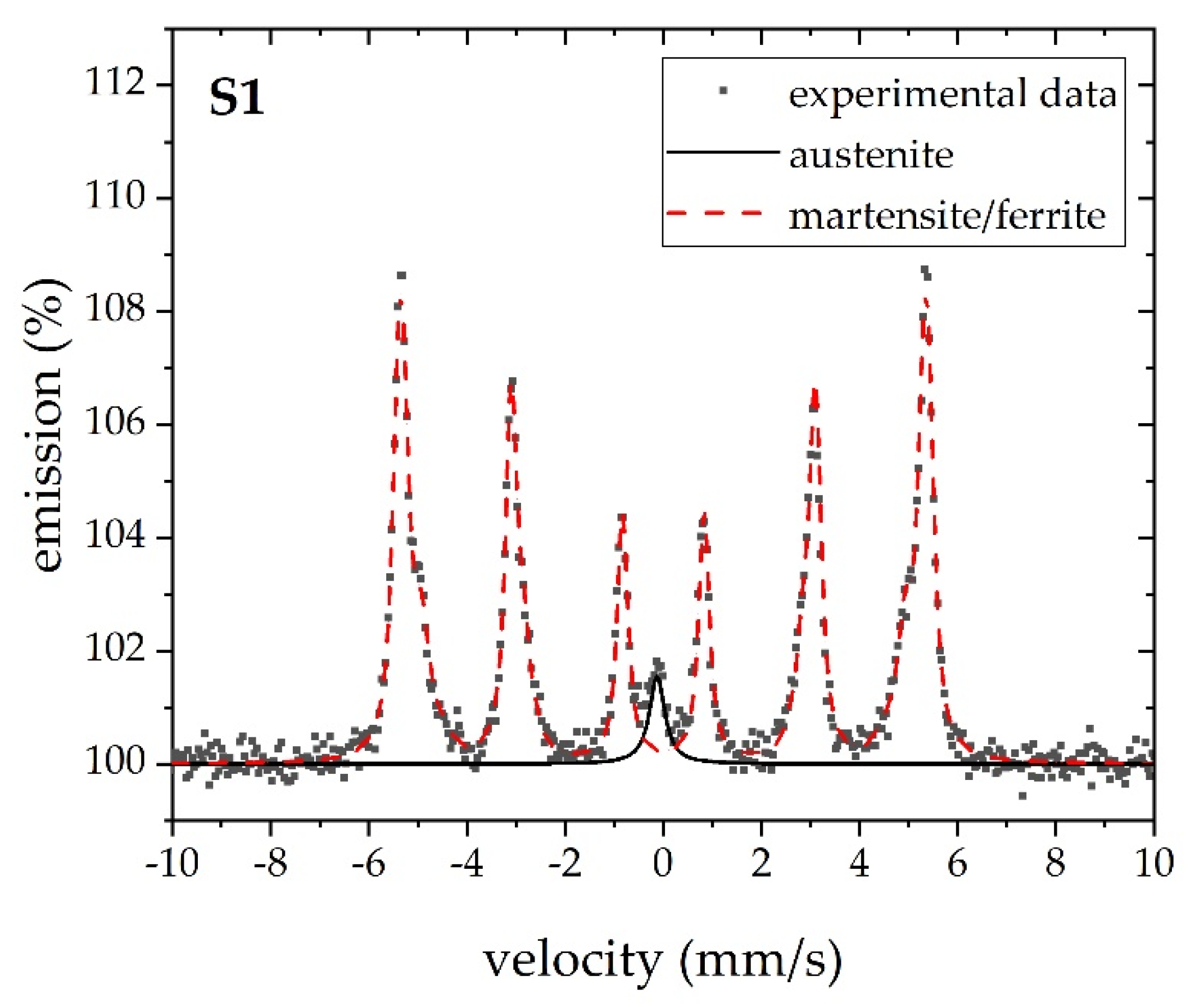
3.3. Conversion X-ray Mössbauer Spectroscopy

CXMS spectra were acquired and processed by described steps. CXMS spectrum of sample S1 measured in backscattering geometry is presented in Figure 4.
It is evident from Figure 2 that the major contribution to the Mössbauer spectrum is arising from the Fe atoms in the martensite/ferrite, while the central minor contribution arises from austenite. All Mössbauer spectra having a similar shape as for sample S1 were satisfactorily evaluated (χ2 better than 1.5) as the superposition of singlet belonging to austenite and magnetic component with a hyperfine field distribution associated with martensite/ferrite. Mössbauer spectra of primary samples are presented in Supplementary Materials in Figure S8.
The fitting curves in the spectrum of S1 recorded at low-velocity interval ±2 mm/s in Figure 5 prove the validity of the model for singlet describing paramagnetic austenite.
As mentioned above, only one singlet was used to calculate the austenite content, as no paramagnetic doublets were registered for either austenite or paramagnetic carbides. Additionally, no ferromagnetic carbides (cementite) and relevant subspectra were found in the spectra. The average hyperfine field B*hf (T) was calculated based on the interval of hyperfine magnetic fields (between 25 T and 37 T). The analysis of the hyperfine field distributions was roughly consistent with the random distribution of the alloying elements in the FCC ferrite lattice at the actual sample composition.
From the main point of view in this study, the relative spectral area of the austenite singlet lines was analyzed. Selected parameters that resulted from the fitting of the obtained spectra for primary samples are listed in Table 3.
In Table 3, the δγ values of austenite are in the expected region around −0.1 mm/s and its LWγ have acceptable values, while some variations of δγ and LWγ can be caused by small transformations in austenite grains. The amount of retained austenite Mγ was calculated according to Equation (1) and it is presented in Table 3. Hyperfine parameters of martensite subspectra remain almost constant and independent of the treatment. Only relative areas of Aα change in opposite to Aγ according to the sample surface transformation caused by the surface treatment. The average hyperfine magnetic field B*hf of martensite is slightly lower than for pure metallic α-Fe, which corresponds with allowing elements’ substitution of iron atoms in BCC structure. In Table 3, the changes in Mγ caused by surface treatment are visible.
The same MS analyses were performed on secondary samples’ series, and the results are listed in Table 4. Mössbauer spectra of secondary samples are presented in Supplementary Materials in Figure S9.
In Table 4, almost uniform results for all listed hyperfine parameters and relative areas are visible. Additionally, the resulting retained austenite is equal within the experimental error for all secondary samples, which demonstrates the microstructure uniformity in the bulk material together with the reproducibility of the sample (surface) treatments and MS measurements. No different heat treatment for the different samples was applied, therefore, the material (and the amount of retained austenite) is the same. Additionally, the SEM image of S3-P-EP was recorded in the backscattered electrons (BSE) mode. A representative SEM/BSE image is presented in Supplementary Materials in Figure S10. Finally, the EBSD images of S3-P-EP and S4-P-EP were recorded (core, central parts of the disks). Both EBSD images are presented in Supplementary Materials in Figures S11 and S12. In both figures, the EBSD maps, phase maps without boundaries, and phase maps with boundaries are presented.

4. Discussion

The main research results as the austenite content were derived from CXMS. The most surprising result on primary samples is the change in the amount of retained austenite as a result of successive grindings and then polishing, which is shown in Table 3. This shows that after the first grinding of the hardened cut sample, which results in a large decrease in the retained austenite, there is a gradual increase in the austenite content due to successive abrasions. After the final polishing, a large decrease in the austenite content was observed.
To understand the observed changes, we need to consider the following. (1) The stress and heat effects are applied to the same sample during successive grinding and polishing. (2) The determination of the austenitic content was monitored at an effective distance of about 20 µm from the polished surface to the inside of the steel.
The considerable decrease in the austenite content can be well explained by the fact that a high degree of heat transfer that occurred during the first grinding resulted in a significant decomposition of the retained austenite. This is well in good agreement with the equilibrium thermodynamic requirements [35] for structural and weathering steels (overall alloy content less than 3–4%); here, the retained austenite is metastable at room temperature and easily transforms by aging. Our observed austenite decrease is also supported by the experimental data found by Mössbauer measurements in the worn surface of bainitic steel [36] and the case of the polished surface of LC200N steel [18].
The increase in austenite content due to grinding seems to be surprising in the 42CrMo4 steel. However, for steels being in the stainless steel composition range, even with a slightly lower chromium content in turbine blade steels, austenite growth was already observed in bulky samples by transmission MS and XRD upon heat treatment at several hundred degrees [33,37,38,39]. Polishing-induced austenite in very thin steel surface layers (<0.2 µm) has already been shown by CEMS when no austenite was detectable in a few micrometer distances from the surface and the bulk [14]. However, in another case, CEMS revealed only the formation of nitride upon polishing of stainless steel [16]. On the surface of X6CrNiTi1810 and X2CrNi1911 austenitic steels, in the depth of about 0.2 µm, Miglierini et al. [21] found by CEMS that the effect of successive grinding, polishing, and chemical polishing results in an increase of the relative amount of paramagnetic phase, attributable mainly to austenite. Recently, EBSD indicated [19] an increase of austenite after several surface treatments including grinding and polishing on the surface of 1540Nb steels with a composition that is much closer to ours than to that of stainless steel.
To describe the effects of stress on phase transformation in grinding, a thermal-mechanical–metallurgical direct coupling finite element model of grinding was developed [20]. The model’s predictions are in fairly good agreement with the experimental results obtained for low-alloyed steels. Calculations for the determination of cutting forces in grinding related to the estimation of the thickness of the removed layer and the depth of the effect of treatment are also available [40].
The thermal effects due to the stress field of each grinding may overlap with each other as a function of the distance from the surface. This corresponds to a series of heat treatments applied in succession to samples subjected to multiple grindings. As the strength of the successive grindings was decreasing, the range of multiple heat treatments could be encapsulated. The multiple heat treatment can be considered similarly as in third-generation low-alloy steels developed under M3 microstructure control [41]. Here, the multistep intercritical heat treatments result in a multiphase microstructure, favoring the development of retained austenite as well as multiscale precipitates [41]. In our case, the occurrence of various paramagnetics could not be completely ruled out based on the analysis of the Mössbauer spectra, as their spectral contribution might overlap with the spectrum of austenite [10].
The gradual increase in austenite content after multiple grinding can be well explained by multiple heat treatments, which can be considered similar to what was previously observed in low-alloy steels subjected to multistep tempering [42].
If the last polishing is outside the range of heat effects caused by previous abrasions, the decrease in austenite content caused by the last polishing can be explained similarly to the first grinding. We should take also into consideration that CXMS provides information of about 20 µm along with the removed thickness by the individual grinding.
No (iron) carbides were detected by XRD nor MS in our as-quenched state samples. In such types of steel, Fe carbide cementite (Fe3C), Mn carbide (Mn3C), and/or Cr carbide (Cr23C6) can be present in heat-treated states. Even in work [23] of the same 42CrMo4 steel being in heat-treated and soft annealed state cementite, Fe3C was distinguished roughly by XRD and by MS, also Mn carbide Mn3C and Cr23C6 carbide, where Fe atoms substitute Cr atoms in this carbide and allow to observe it by MS.
According to the experimental description of secondary samples’ preparation, samples were repeatedly completely ground and polished (Table 2) and measured by CXMS to get an average value of austenite as a standard method. With these measurements, we can determine the austenite content in the bulk of the material and evaluate the precision of the MS method. We can consider variations of austenite and alloying elements within the original steel rod too.
The austenite content in the surface-treated samples of the second series is essentially the same for all samples. The amount of austenite is independent of the austenite content of the samples observed after the first treatments. Furthermore, this austenite content can correspond to the original austenite content of the as-quenched state of the untreated sample. This can indicate that the successive surface treatments determined in Table 2 do not influence essentially the austenite content if it is applied on an already surface-treated as-quenched steel state.
The equal distribution of austenite in the samples after the second surface treatment may weaken somewhat the consideration of the model of the subsequent grindings and polishing discussed above. It may suggest that the significant differences between the austenite contents in the first series can be associated rather with the structural inhomogeneities of the as-quenched and cut surfaces of the different steel samples. In this case, our first series of experiments can give important information about the fluctuation of austenite content on the surface-treated quenched state of 42CrMo4 steel. Our findings can also indicate that appropriate removing a few times of 10 µm of the surface layer can result in a more homogeneous surface for a new series of grindings and polishing. However, the heat effect of the previous polishing may also be contributed to the formation of the more homogenized layer. Similarly, authors in [18] concluded that polishing probably removed some amount of austenite from the near-surface regions.
From the EBSD images in Figures S11 and S12, the amount of retained austenite results quite low, about 0.10% and 0.03% resp., so we can conclude that only a very low amount of austenite occurs in the microstructure of studied sample surfaces. This is mainly due to the austenite grain size where EBSD results do not reflect the real austenite occurrence.

5. Conclusions

In this study, we focused on the determination of the percentage amount of retained austenite in the steel as a consequence of successive grinding and polishing. To observe such phenomena, mainly 57Fe Mössbauer spectroscopy measurements were applied to characterize the metallurgical state of 42CrMo4 steel samples. Mössbauer spectroscopy was applied to determine the quantity of retained austenite, as one of the most accurate methods, in as-quenched 42CrMo4 steel after cutting and successive grinding and polishing. The XRD analysis shows insufficiently reliable data in the present case.
The observed changes in austenite content can be understood by considering that the effect of successive grindings means successive heat treatment of about 20 µm in the CXMS monitored range. We observed that surface treatment processing affects the steel phase transformation within the thickness of a few µm surface layer, which is mostly considered as bulk material characterization. This phenomenon can lead to incorrect interpretation and material description after grinding and polishing of metallographic samples. Surprising is the result for sample S1, where polishing does not affect the amount of austenite (see Table 3 and Table 4). This result shows that it can be enough to cut the sample and no further grinding or polishing of the sample is required. This idea will be further studied for other types of steel.
The results of the second series may inform us that about 5% of retained austenite can be characteristic for 42CrMo4 steel in an as-quenched state. This result can be consistent with those found for annealed 42CrMo4 steel cases [23,24].
Due to the small amount of retained austenite in the microstructure and its ultra-fine grain size, an EBSD technique is not suitable for its detection. This statement was previously confirmed in [26]. On the other hand, CXMS proved to deliver the correct percentage of retained austenite in all samples. With such observations, we can present MS as a highly valuable method for industry engineering and metallography purposes.

Supplementary Materials

The following are available online at https://www.mdpi.com/article/10.3390/met12010119/s1, Table S1: EDS analysis (wt. %) of alloying elements in primary samples, Figure S1: EDS line mapping on the S1 surface, Figure S2: XRD pattern of sample S1, Figure S3: XRD pattern of sample S2, Figure S4: XRD pattern of sample S3, Figure S5: XRD pattern of sample S4, Figure S6: XRD pattern of sample S5, Figure S7: XRD pattern of sample S6, Figure S8: Mössbauer spectra of primary samples (a) S1, (b) S2, (c) S3, (d) S4, (e) S5, and (f) S6, Figure S9: Mössbauer spectra of secondary samples (a) S1-P, (b) S2-P, (c) S3-P-EP, (d) S4-P-EP, (e) S5-P, and (f) S6-P, Figure S10: SEM/BSE (backscattered electrons) regime microscopy image of sample surface S3-P-EP, Figure S11: EBSD image of sample surface S3-P-EP central part (core), Figure S12: EBSD image of sample surface S4-P-EP central part (core).

Author Contributions

Conceptualization, J.P., E.K. and R.V.; Data curation, J.P., E.K., R.V., V.V., L.K. and P.K.; Formal analysis, R.V., T.I. and M.M.; Investigation, J.P. and A.O.; Methodology, J.P., E.K., R.V., A.O., V.V., L.K., T.I., P.K. and M.M.; Project administration, M.M.; Resources, J.P., A.O. and M.M.; Validation, E.K., A.O., V.V., L.K., T.I. and P.K.; Writing—original draft, J.P., E.K. and R.V.; Writing—review and editing, V.V., L.K., T.I. and P.K. All authors have read and agreed to the published version of the manuscript.

Funding

This research was funded by internal IGA grant of Palacký University (IGA_PrF_2021_003) and the Czech Ministry of Education, Youth and Sports, grant number CZ.02.1.01/0.0/0.0/17_049/0008408.

Institutional Review Board Statement

Not applicable.

Informed Consent Statement

Not applicable.

Data Availability Statement

Relevant data have been shown in the paper and Supplementary Materials.

Acknowledgments

Authors acknowledge the help of Vít Procházka and Filippos Georgiadis.

Conflicts of Interest

The authors declare no conflict of interest. The funders had no role in the design of the study; in the collection, analyses, or interpretation of data; in the writing of the manuscript, or in the decision to publish the results.

References

  1. Singh, S.B. Mechanisms of bainite transformation in steels. In Phase Transformations in Steels: Fundamentals and Diffusion-Controlled Transformations, 1st ed.; Pereloma, E., Edmons, D.V., Eds.; Woodhead Publishing: Oxford, UK; Cambridge, UK; Cambridge, UK; Philadelphia, PA, USA; New Delhi, India, 2012; Volume 1, pp. 385–416. [Google Scholar]
  2. Palombarini, G.; Carbucicchio, M. Materials and surface treatments for tribological applications. Hyperfine Interact 1998, 111, 101–111. [Google Scholar] [CrossRef]
  3. Kholmetskii, A.L.; Uglov, V.V.; Khodasevich, V.V.; Anishik, V.M.; Ponaryadov, V.V.; Mashlan, M. Application of the Mössbauer effect in some tribological problems. In Mössbauer Spectroscopy in Materials Science, 1st ed.; Miglierini, M., Petridis, D., Eds.; Kluwer Academic Publishers: Dordecht, The Netherlands, 1999; Volume 66, pp. 215–226. [Google Scholar] [CrossRef]
  4. Yingjie, L.; Xingui, B.; Keqiang, C. A study on the formation of wear debris during abrasion. Tribol. Int. 1985, 18, 107–111. [Google Scholar] [CrossRef]
  5. Zambrano, A.; Valdés, J.; Rodriguez, L.A.; Reyes, D.; Snoeck, D.; Rodríguez, S.A.; Coronado, J.J. Elucidating the role of κ-carbides in FeMnAlC alloys on abrasion wear. Tribol. Int. 2019, 135, 421–431. [Google Scholar] [CrossRef]
  6. Changle, Z.; Shouhai, L.; Hanguang, F.; Yinghua, L. Microstructure evolution and wear resistance of high silicon bainitic steel after austempering. J. Mater. Res. Technol. 2020, 9, 4826–4839. [Google Scholar] [CrossRef]
  7. Schwartzendruber, L.J.; Bennett, L.H.; Schoefer, E.A.; Delong, W.T.; Campbell, H.C. Mössbauer-effect examination of ferrite in stainless steel welds and castings. Weld. Res. Suppl. 1974, 1s–12s. [Google Scholar]
  8. Wagner, F.E. Applications of Mössbauer scattering techniques. J. De Phys. 1976, 37, C6-673-689. [Google Scholar] [CrossRef]
  9. Longworth, G. The use of Mössbauer spectroscopy in non-destructive testing. NDT Int. 1977, 10, 241–246. [Google Scholar] [CrossRef]
  10. Kuzmann, E.; Domonkos, L.; Kocsis, M.; Nagy, S.; Vertes, A.; Mehner, H. Determination of retained austenite in steels alloyed with carbide formers. J. De Phys. 1979, 40, C2-627-629. [Google Scholar] [CrossRef]
  11. Zemčík, T.; Havlicek, S. Fast Mössbauer austenitometer. In Proceedings of the International Conference on Mössbauer Spectroscopy, Bucharest, Romania, 1st ed.; Barb, D., Tarina, D., Eds.; Central Institute of Physics: Bucharest, Romania, 1977; pp. 405–406. [Google Scholar]
  12. Pechousek, J.; Kouril, L.; Novak, P.; Kaslik, J.; Navarik, J. Austenitemeter—Spectrometer for rapid determination of residual austenite in steels. Measurement 2019, 131, 671–676. [Google Scholar] [CrossRef]
  13. Schwartz, L.H. Quantitative Analysis Using Mössbauer Effect Spectroscopy. Int. J. Non-Destr. Test. 1970, 1, 353–359. [Google Scholar]
  14. Schwartzendruber, L.J.; Bennett, L.H. Retained austenite developed during surface grinding of a carbon steel. Scr. Met. 1972, 6, 737–742. [Google Scholar] [CrossRef]
  15. Fornal, P.; Stanek, J.; Gawlik, J.; Wantuch, E.; Binczycka, H. Surface modifications of upgraded high-speed tool steel. Hyperfine Interact 1994, 92, 1355–1360. [Google Scholar] [CrossRef]
  16. Vertes, C.; Vass, G.; Kuzmann, E.; Romhanyi, K.; Lakatos-Varsanyi, M.; Vertes, A. Conversion electron Mössbauer and XPS study on the effect of polishing of a stainless steel sample. J. Radioanal. Nucl. Chem. Lett. 1994, 186, 447–454. [Google Scholar] [CrossRef]
  17. Jiraskova, Y.; Schneeweiss, O.; Van Hoecket, T.; Segers, D.; Dauwe, C. Investigation of defects and stresses in SiFe steel surfaces. J. Magn. Magn. Mater. 2000, 215–216, 118–120. [Google Scholar] [CrossRef]
  18. Pašteka, L.; Miglierini, M.; Bujdoš, M. Identification of Magnetic Phases in LC200N Steel by Backscattering Mössbauer Spectrometry. Acta Phys. Pol. A 2017, 131, 1078–1080. [Google Scholar] [CrossRef]
  19. Pinto, L.A.; Escobar, D.P.; Santos, O.S.H.; Lopes, N.I.A.; Carneiro, J.R.G.; Ribeiro-Andrade, R. Influence of surface preparation method on retained austenite quantification. Mater. Today Commun. 2020, 24, 101226. [Google Scholar] [CrossRef]
  20. Xiu, S.; Deng, Y.; Kong, X. Effects of stress on phase transformations in grinding by FE modeling and experimental approaches. Materials 2019, 12, 2327. [Google Scholar] [CrossRef] [Green Version]
  21. Miglierini, M.; Pašteka, L.; Cesnek, M.; Kmječ, T.; Bujdoš, M.; Kohout, J. Influence of surface treatment on microstructure of stainless steels studied by Mössbauer spectrometry. J. Radioanal. Nucl. Chem. 2019, 322, 1495–1503. [Google Scholar] [CrossRef]
  22. Brnic, J.; Krscanski, S.; Brcic, M. Comparison of the mechanical behavior of materials subjected to specific operating conditions. IOP Conf. Ser. Mater. Sci. Eng. 2018, 378, 012007. [Google Scholar] [CrossRef]
  23. Bulin, T.; Svabenska, E.; Hapla, M.; Roupcova, P.; Ondrusek, C.; Schneeweiss, O. Magnetic properties of 42CrMo4 steel. IOP Conf. Ser. Mater. Sci. Eng. 2017, 179, 012010. [Google Scholar] [CrossRef] [Green Version]
  24. Siemiątkowski, Z.; Gzik-Szumiata, M.; Szumiata, T.; Rucki, M.; Martynowski, R. Metallurgical quality evaluation of the wind turbine main shaft 42CrMo4 steel: Microscopic and Mössbauer studies. Nukleonika 2017, 62, 171–176. [Google Scholar] [CrossRef] [Green Version]
  25. Kouril, L.; Pechousek, J.; Novak, P.; Navarik, J.; Kohout, P. Toroidal proportional gas flow counter for conversion X-ray Mössbauer spectroscopy. Nucl. Inst. Methods Phys. Res. B 2018, 432, 55–59. [Google Scholar] [CrossRef]
  26. Olina, A.; Píška, M.; Petrenec, M.; Hervoches, C.; Beran, P.; Pechoušek, J.; Král, P. Assessment of retained austenite in fine grained inductive heat treated spring steel. Materials 2019, 12, 4063. [Google Scholar] [CrossRef] [Green Version]
  27. Klencsár, Z.; Kuzmann, E.; Vértes, A. User-friendly software for Mössbauer spectrum analysis. J. Radioanal. Nuclear Chem. 1996, 210, 105–118. [Google Scholar] [CrossRef]
  28. –Klencsár, Z.; Kuzmann, E.; Vértes, A. User-Friendly Program for Multifold Evaluation of Mössbauer Spectra. Hyperfine Interact. 1998, 112, 269–274. [Google Scholar] [CrossRef]
  29. Kuzmann, E.; Bene, E.; Domonkos, L.; Hegedűs, Z.; Nagy, S.; Vértes, A. Structure investigation and phase analysis of Fe-Cr carbides. J. De Physique 1976, 37, C6-409-414. [Google Scholar] [CrossRef]
  30. Fujita, F.E. Mössbauer Spectroscopy in Physical Metallurgy. In Mössbauer Spectroscopy, 1st ed.; Gonser, U., Ed.; Springer: Berlin/Heidelberg, Germany; New York, NY, USA, 1975; pp. 201–237. [Google Scholar]
  31. Suwalski, J.; Kucharski, Z.; Lukasiak, M. Determination of retained austenite in bearing steel. Hyperfine Interact. 1986, 29, 1491–1494. [Google Scholar] [CrossRef]
  32. Uwakweh, O.N.C.; Bauer, J.P.; Genin, J.M.R. Mössbauer study of the distribution of carbon interstitials in iron alloys and the isochronal kinetics of the aging of martensite: The clustering-ordering synergy. Metall. Trans. A 1990, 21A, 589–602. [Google Scholar] [CrossRef]
  33. Varga, I.; Kuzmann, E.; Káldor, M.; Vértes, A. Mössbauer study of the kinetic behavior of anomalous austenite formation in Fe-12Cr-4Ni steel. J. Radioanal. Nucl. Chem. 1992, 165, 115–126. [Google Scholar] [CrossRef]
  34. Wyckoff, R.W.G. Crystal Structures, 2nd ed.; Interscience Publishers: New York, NY, USA, 1963; Volume 1, pp. 7–83. [Google Scholar]
  35. Cahn, R.W. Physical Metallurgy, 1st ed.; Elsevier: Amsterdam, The Netherlands; London, UK; New York, NY, USA, 1965; pp. 281–381. [Google Scholar]
  36. Zhang, F.C.; Zheng, Y.Z.; Ruifu, Z.; Tingquan, L. Mössbauer studies on aging of deformed Fe–6Mn–2Cr–1C alloy. Scr. Metall. Mater. 1995, 32, 1477–1481. [Google Scholar] [CrossRef]
  37. Kuzmann, E.; Varga, I.; Vértes, A. Kinetical behaviour of anomalous austenite formation in turbine blade steel. Nucl. Instrum. Methods Phys. Res. B 1996, 76, 292–294. [Google Scholar] [CrossRef]
  38. Kuzmann, E.; Jaen, J.; Vértes, A.; Csöme, L.; Tibiássy, B.; Káldor, M. Mössbauer investigation of austenite formation together with Cr depletion in aged turbine blade steels. Hyperfine Interact. 1990, 58, 2593–2598. [Google Scholar] [CrossRef]
  39. Varga, I.; Kuzmann, E.; Vértes, A. Kinetics of α-γ phase transition of Fe-12Cr-4Ni Alloy aged between 500–650 °C. Hyperfine Interact. 1998, 112, 169–174. [Google Scholar] [CrossRef]
  40. Kalchenko, V.; Yeroshenko, A.; Boyko, S.; Sira, N. Determination of cutting forces in grinding with crossed axes of tool and workpiece. Acta Mech. Et Autom. 2017, 11, 58–63. [Google Scholar] [CrossRef] [Green Version]
  41. Xie, Z.; Shang, C.; Wang, X.; Wang, X.; Han, G.; Misra, R. Recent progress in third-generation low alloy steels developed under M3 microstructure control. Int. J. Miner. Metall. Mater. 2020, 27, 1–9. [Google Scholar] [CrossRef]
  42. Bakhsheshi-Rad, H.R.; Monshi, A.; Monajatizadeh, H.; Idris, M.H.; Kadir, M.R.A.; Jafari, H. Effect of Multi-Step Tempering on Retained Austenite and Mechanical Properties of Low Alloy Steel. J. Iron Steel Res. Int. 2011, 18, 49–56. [Google Scholar] [CrossRef]
Figure 1. SEM image of as-cut samples of S1 surface (left) with carbon and chromium mapping (right).
Metals 12 00119 g001
Figure 2. EDS elemental analysis of sample S1 with main energies depicted.
Metals 12 00119 g002
Figure 3. XRD pattern of sample S1.
Metals 12 00119 g003
Figure 4. Mössbauer spectrum of sample S1 recorded in the wide velocity interval.
Metals 12 00119 g004
Figure 5. High-resolution Mössbauer spectrum recorded at a low-velocity interval of central part for sample S1.
Metals 12 00119 g005
Table 1. List of primary samples treated by successive grinding and polishing.
SampleSurface Treatment
S1cutting, 0.5 mm/s
S2grinding 120 µm + water for 10 min, disc Struers MD-Piano 120
S3as S2 and grinding 220 µm + water for 5 min, disc Struers MD-Piano 220
S4as S3 and grinding 500 µm + water for 3 min, disc Struers MD-Piano 500
followed by grinding 1200 µm + water for 3 min, disc Struers MD-Piano 1200
S5as S4 and polishing 3 µm + alcohol for 5 min,
polishing canvas 3 µm Struers MD-MOL and diamond paste Struers P3
S6as S5 and polishing 1µm + alcohol for 2 min
polishing canvas 1 µm Struers MD-NAP and diamond paste Struers P1
Table 2. List of secondary samples treated by grinding and polishing of primary samples.
SampleSurface Treatment
S1-Ppolishing up to 3 µm
S2-Ppolishing up to 3 µm
S3-P-EPpolishing up to 3 µm, and electrolytic polishing
S4-P-EPpolishing up to 3 µm, and electrolytic polishing
S5-Ppolishing up to 3 µm
S6-Ppolishing up to 3 µm
Table 3. Austenite and martensite contents in primary samples resulting from Mössbauer spectroscopy analysis, where δγ and δα is isomer shift of austenite and martensite pattern resp., LWγ is a line width of austenite, Aγ is a relative area of austenite in the spectrum, B*hf is an average hyperfine field of the martensite subspectrum, Aα is a relative area of martensite in the spectrum, Mγ is the amount of retained austenite according to Equation (1).
Sampleδγ (mm/s)
±0.04 mm/s
LWγ (mm/s)
±0.04%
Aγ (%) 1
±1.0%
δα (mm/s)
±0.04 mm/s
B*hf (T)
±0.3 T
Aα (%) 1
±1.0%
Mγ (%) 1
±1.0%
S1−0.130.384.20.0032.595.84.8
S2−0.060.58 22.30.0032.697.72.6
S3−0.170.502.30.0032.597.72.6
S4−0.120.412.80.0032.597.23.3
S5−0.170.383.70.0032.596.34.3
S6−0.100.241.90.0032.598.12.3
1 The uncertainty of retained austenite measurement is 1%; however, we present the results with one decimal place to highlight differences in results. 2 Fixed values in the fitting process.
Table 4. Austenite and martensite contents in secondary samples resulting from Mössbauer spectroscopy analysis, where δγ and δα is isomer shift of austenite and martensite pattern resp., LWγ is a line width of austenite, Aγ is a relative area of austenite in the spectrum, B*hf is an average hyperfine field of the martensite subspectrum, Aα is a relative area of martensite in the spectrum, Mγ is the amount of retained austenite according to Equation (1).
Sampleδγ (mm/s)
±0.04 mm/s
LWγ (mm/s)
±0.04%
Aγ (%) 1
±1.0%
δα (mm/s)
±0.04 mm/s
B*hf (T)
±0.3 T
Aα (%) 1
±1.0%
Mγ (%) 1
±1.0%
S1-P−0.120.404.20.0032.495.84.8
S2-P−0.120.414.20.0032.595.84.9
S3-P-EP−0.120.254.20.0032.595.84.9
S4-P-EP−0.120.314.30.0032.695.75.0
S5-P−0.100.454.50.0032.595.55.2
S6-P−0.120.313.70.0032.596.34.2
1 The uncertainty of retained austenite measurement is 1%; however, we present the results with one decimal place to highlight differences in results.
Publisher’s Note: MDPI stays neutral with regard to jurisdictional claims in published maps and institutional affiliations.

