Interface of a Al6061/Ti Composite Prepared by Field Assisted Sintering Technique


1
Department of Physics of Materials, Charles University, Ke Karlovu 5, 121 16 Prague, Czech Republic
2
Institute of Plasma Physics, Czech Academy of Sciences, Za Slovankou 1782/3, 182 00 Prague, Czech Republic
*
Author to whom correspondence should be addressed.
Metals 2021, 11(1), 73; https://doi.org/10.3390/met11010073
Submission received: 26 November 2020
/
Revised: 26 December 2020
/
Accepted: 28 December 2020
/
Published: 31 December 2020
(This article belongs to the Section Powder Metallurgy)
Abstract
:Architectured heterogeneous metallic composites consist of two dissimilar materials with a particular focus on spatial arrangement of constituents. This experimental study describes the application of Field Assisted Sintering Technique (FAST) for manufacturing of composite materials by sintering of a bulk reinforcement with a powder metal. Simple structure made of Ti wire (Ti Grade 2) was sintered with Al6061 alloy powder at 560 °C for 10 min. Successful material bonding and evolution of diffusion layer was thoroughly studied by scanning and transmission electron microscopy. Diffusion layer and adjacent precipitates are described as ternary Ti-Al-Si τ1 and τ2 phases. Si, as an alloying element in the Al6061 alloy, significantly affects the formation of the diffusion layer at the material interface due to its high inter-diffusion coefficient in both Al and Ti. Detailed TEM analysis also showed a modulated τ1/τ2 structure resembling a long-period stacking order (LPSO) phase, which has not been previously reported in the Ti-Al-Si ternary compounds. FAST is capable to manufacture composites from dissimilar constituents, which opens new possibilities for design and manufacturing of architectured materials.
1. Introduction
Composite, hybrid, heterogeneous and architectured materials consist of two or more constituents and aim to achieve better properties than each of the constituents individually. While composite refer to any material made of two or more constituents, the term ‘hybrid’ relates mostly to materials with two constituents at sub-micrometer level [1]. The term ‘heterogeneous’ underlines very dissimilar properties of constituents or domains [2], and, finally the term ‘architectured’ refers to inner architecture of the material at a length scale intermediate between the microstructural scale and the specimen dimensions focusing on spatial arrangement of constituents [3]. Architectured composites combine two (or more) materials or a material and an empty space (for instance cellular structures) in chosen configuration and scale as pioneered by Ashby and Brechet [4].
Powder metallurgy technique of additive manufacturing (3D printing) allows manufacturing of architectured metallic cellular materials with arbitrary design as described in dozens of papers [5,6,7,8]. Direct laser deposition was successfully used for manufacturing of architectured composite consisting of Inconel matrix and Co-Cr internal structure in a proof-of-concept study [9].
In the present study we use another powder metallurgy method known as Spark Plasma Sintering (SPS) or more appropriately Field Assisted Sintering Technique (FAST) to manufacture architectured structure consisting of two different metals. Using of FAST for metal matrix composites (MMCs) is well established, however, only based on mixing of powders, i.e., without a particular architecture [10,11,12,13].
Inspired by [14] we investigate the possibility of application of the Field Assisted Sintering Technique for manufacturing of a metallic composite composed of a bulk metal and a metallic powder. Such method was used for manufacturing of Ti based composites [14] and tungsten based composites [15]. However, in both cases the bulk and powder constituents consisted of the same metal.
The present study shows a feasibility of FAST for manufacturing of architectured composites consisting of Ti-based bulk and compacted Al-based powder. Experimental characterization of each of the constituents and, in particular, their bonding is of critical importance for determination of material properties and optimization of their processing [9].
During FAST, the sample is heated by high current passing directly through the sample. However, a series of papers showed that there is no special particular effect of the passing electric current [16,17,18]. Therefore, during the field assisted sintering, rather common solid-state diffusion bonding occurs under static pressure [19], and inter-diffusion takes place between the two base metals [20]. Diffusion bonding of Ti and Al results in a formation of intermetallic compounds at the Al/Ti interface such as Al3Ti [21,22,23]. Their control is critical for achieving the best mechanical properties of the bond [24,25]. In the particular case of bonding Ti and Al alloys, intermetallic layers are also strongly affected by alloying elements in the Al alloy such as Mg and Si [21], resulting in formation of ternary compounds, for instance (Al,Si)3Ti, Al18Mg3Ti2 [22], Al2Mg3Zn3 [26].
2. Materials and Methods
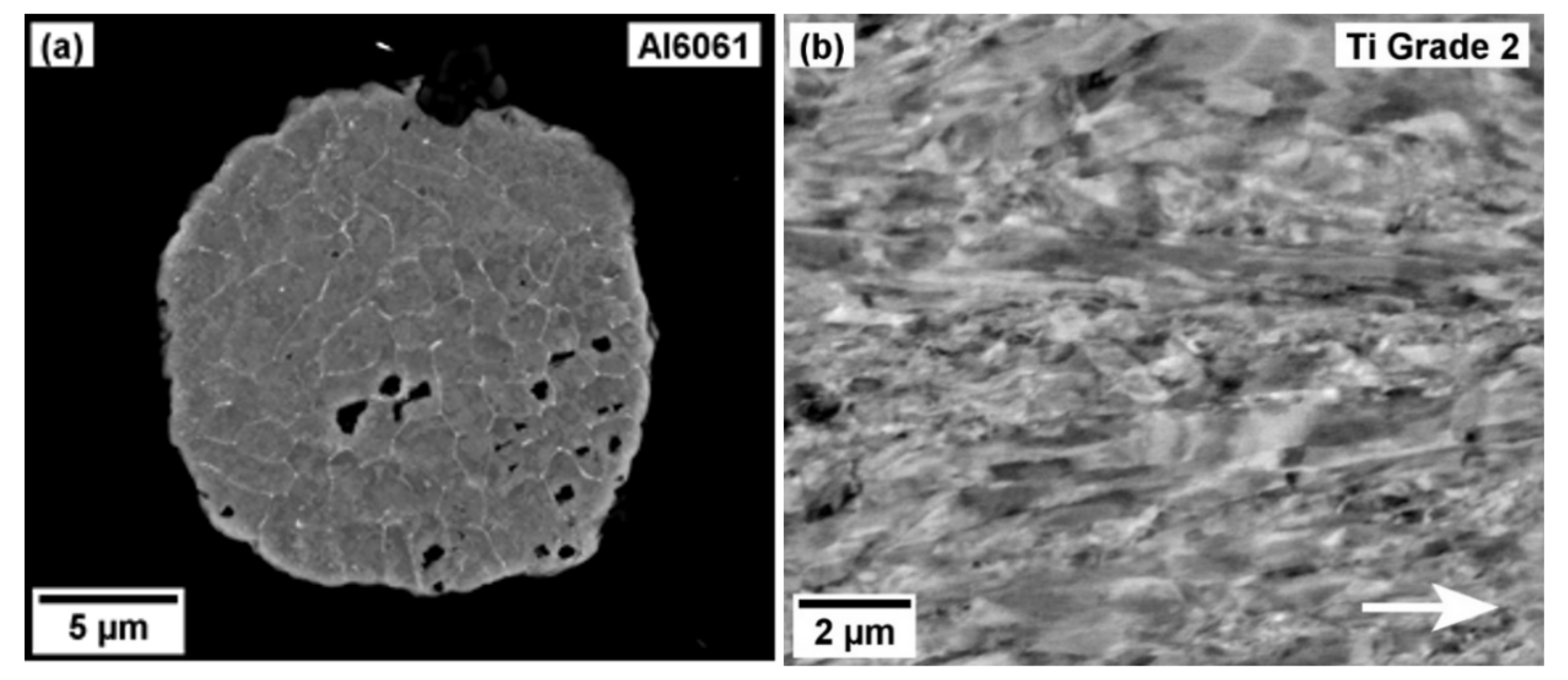
6061 aluminium alloy powder was supplied by TLS Technik GmbH, Germany, with the composition summarized in the Table 1. The alloy was selected for its widespread use in industry to prove the viability of the concept. The particle size used was in the range of 10–45 μm and the particle cross-section is shown in Figure 1a.
A commercially pure Ti (Grade 2) wire of 0.5 mm in thickness supplied by INKOSAS a. s., Czechia was used as the reinforcement. Its microstructure is presented in the Figure 1b. To show the proof of concept, the wire was simply manually woven to a small 3D wireframe structure of approximately 8 × 8 × 8 mm3, which was then inserted into the partially pre-filled sintering die (2 g of Al6061 powder) of 20 mm in diameter. The die was finally topped up with 6 g of Al6061 powder.
Spark plasma sintering was performed on SPS 10-4 machine (Thermal Technology LLC, Santa Rosa, CA, USA) by high non-pulsed direct current using carefully designed sintering program. As the aluminium and titanium have different coefficients of thermal expansion (22 × 10−6 K−1 and 6 × 10⁻⁶ K−1, respectively), it is important to create a coherent layer of intermetallic products at their interface to prevent cracking during cooling phase of the sintering. The sintering program was designed with several considerations:
- 1.
- The temperature must be as high as possible to promote diffusion between the matrix and reinforcement.
- 2.
- The temperature has to be below the solidus temperature of Al6061 alloy (582 °C, [27]) to prevent melting.
- 3.
- The temperature should be above the solvus temperature of various intermetallic phases which can be created (Mg2Si, Ti3Al) [28].
- 4.
- The piston pressure should be kept low and applied slowly to promote plastic deformation of the Al6061 particles, while suppressing the deformation of the reinforcement wireframe structure.
The sintering temperature was set to 560 °C for 10 min and the maximum piston pressure was 10 MPa. The course of process variables during sintering is presented in the Figure 2. The heating rate of 50 °C/min was used. The cooling rate can be controlled only by heating and was also set to 50 °C/min. However, below 430 °C the real cooling rate is lower as seen from Figure 2. The sample was heated by electric current. The maximum current at the end of the heating was 631 A, electric current during holding was 500 ± 10 A. The produced samples are cylinders with dimensions of 20 mm in diameter and approximately 9 mm in height.
The samples for a scanning electron microscopy (SEM) were prepared by conventional cutting and grinding. Due to the difficulties with the polishing of dissimilar materials, ion polishing was used as the last polishing step using Leica EM RES102 system. SEM investigations and sample preparation for transmission electron microscopy (TEM) were performed on Zeiss Auriga Compact microscope (Carl Zeiss AG, Oberkochen, Germany) equipped with energy dispersive X-ray spectroscopy (EDS, Ametek Inc., Berwin, PA, USA) and FIB system. TEM was done on JEOL 2200FS microscope (Jeol Ltd., Tokyo, Japan).
Microhardness measurements were performed using a Qness Q10A automatic testing machine (QATM, Salzburg, Austria) with a Vickers pyramidal indenter under the load of 0.5 kgf (HV0.5) and the dwell time of 10 s.
3. Results
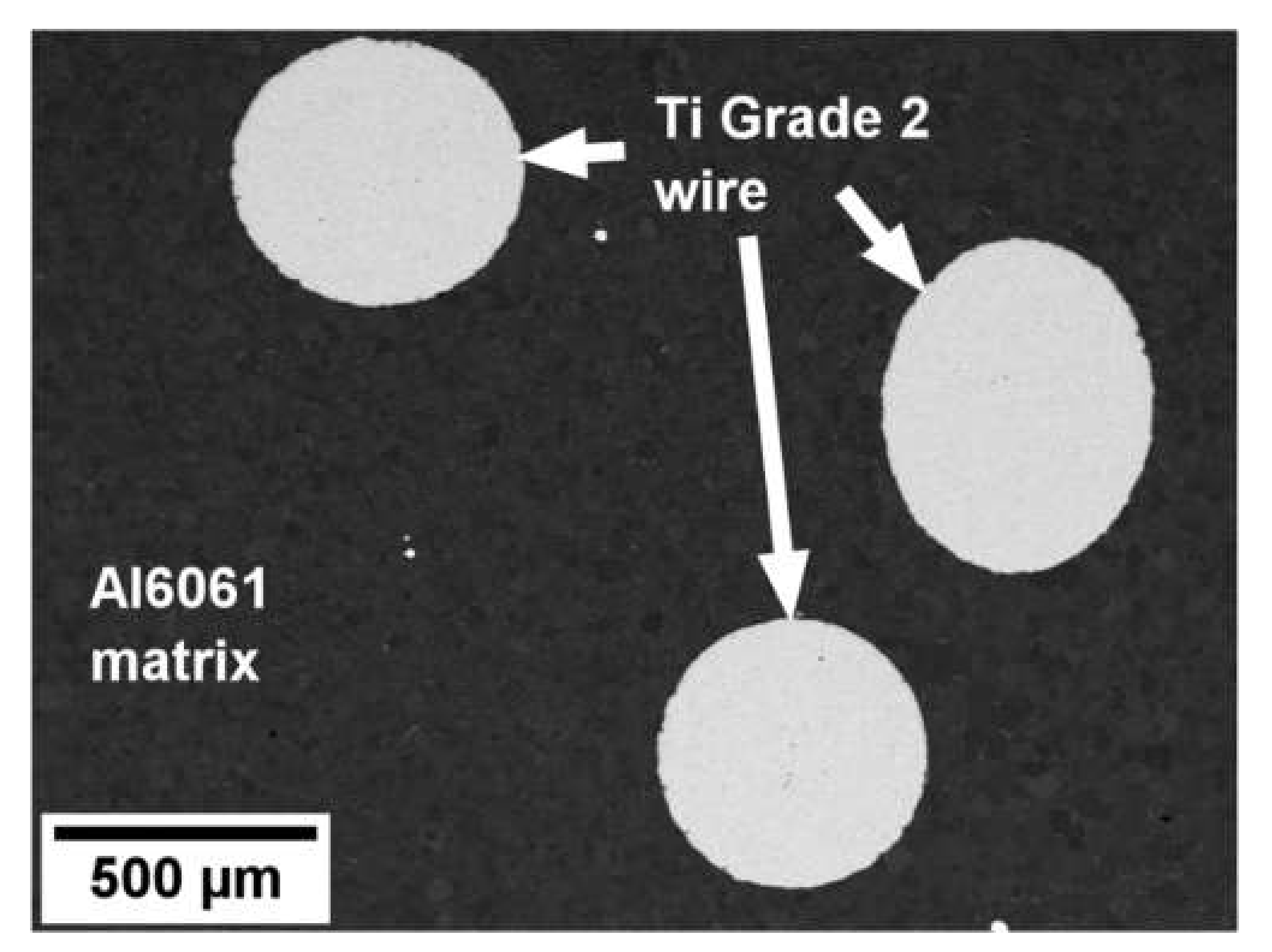
The general overview of the Ti wire embedded in the Al6061 matrix is shown in Figure 3. Unfortunately, the original Ti wireframe cannot be observed in this random cut. On the other hand, we can observe only limited macroscopic deformation of Ti wires. Due to the relatively high sintering temperature, no porosity was identified within the Al-based matrix. This is consistent with the observed stop of the piston movement at the end of the dwell during sintering, cf. Figure 2. Bulk microhardness of the Ti wire and the Al6061 matrix was measured after sintering, the results are presented in the Table 2. 10 MPa is well above the yield strength of the Al6061 alloy at the sintering temperature [27]. The matrix is therefore assumed to yield easily and be in a full contact with the Ti wire during the isothermal stage of the sintering.
Bulk microhardness of both the Ti wire and the Al6061 matrix was measured after sintering, the results are presented in the Table 2. These values are consistent with the typical values of the alloys and their thermomechanical history [28,29].
Al6061 alloy is an age-hardened Al-Mg-Si alloy and its microhardness reaching 100 HV after T6 treatment is predominately related to the precipitation [24,30]. A high temperature during the sintering process leads to the reduced the microhardness of Al6061 alloy. The sintering temperature of 560 °C results in grain growth in CP Ti [31] causing a slightly decreased microhardness [32].
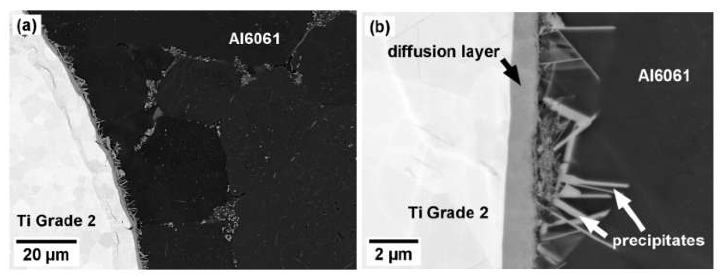
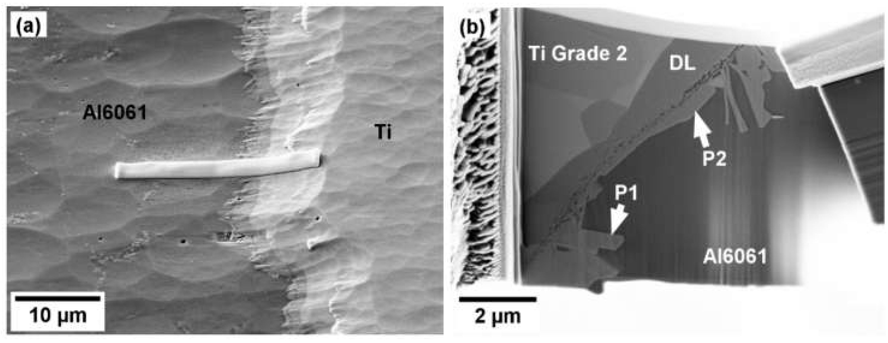
The interface is presented in a greater detail in Figure 4. A continuous diffusion layer and numerous precipitates were found in the sample. The thickness of the diffusion layer typically varies between 1 and 2 μm.
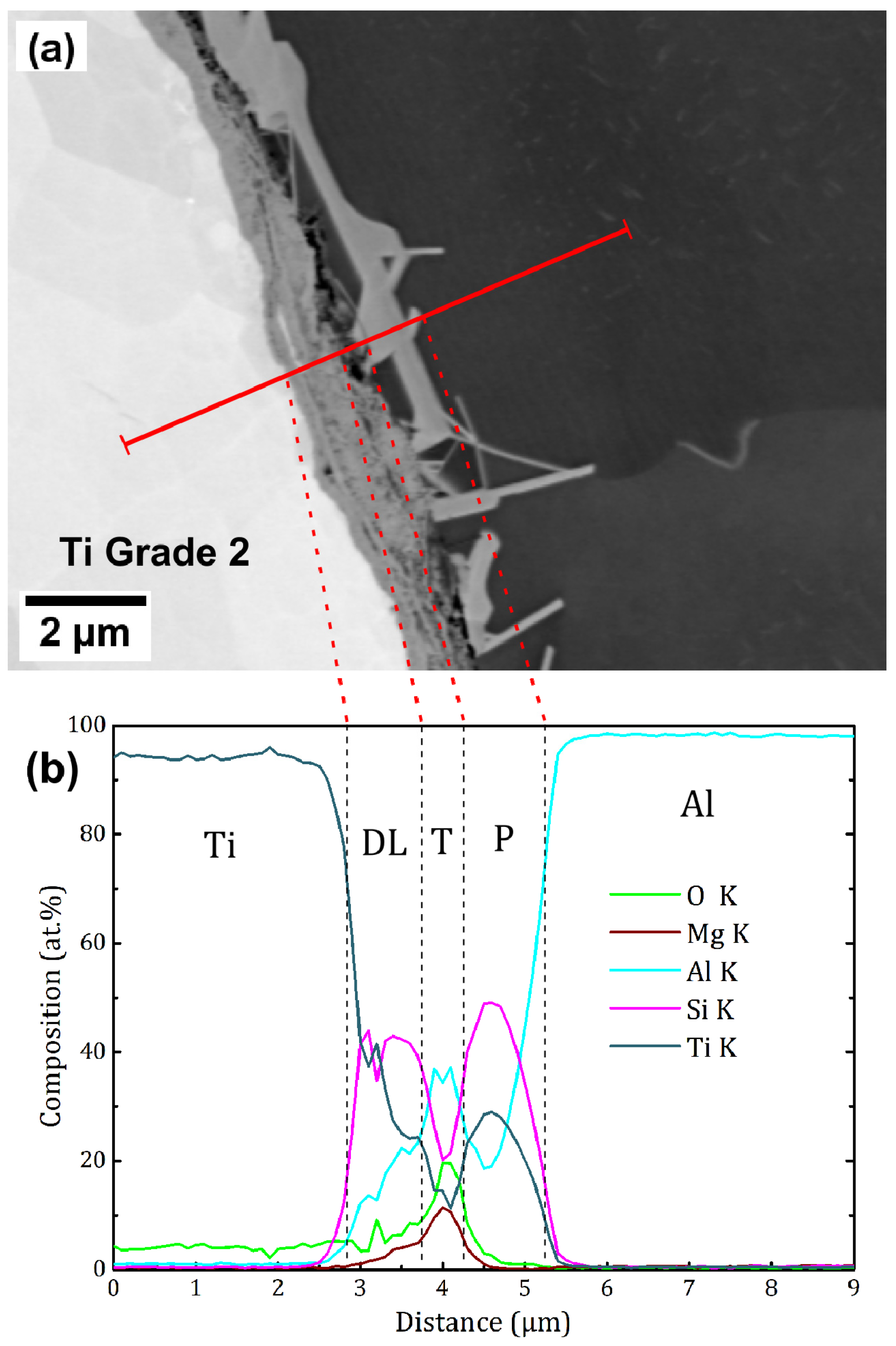
An EDS line scan was performed across the interface in the specimen, as illustrated in Figure 5a, and the resulting composition profile is shown in Figure 5b. Apart from the wire (marked Ti) and the matrix (marked Al), three distinctive regions can be identified along the line. The first, the diffusion layer in the wire strongly enriched with Si and moderately with Al (marked DL); the second, the transition layer with a high Mg and Al content (marked T) and the third, the precipitate in the Al6061 matrix having again high Si, Ti and Al content (marked P).
Diffusion coefficients and diffusion lengths were calculated for the selected elements and are shown in the Table 3. Only the isothermal part of the sintering program was taken into account, as its contribution is most important due to the exponential dependence of a diffusion coefficient on temperature.
The higher content of silicon observed in the diffusion layer than that of aluminium can be explained by the significant difference in diffusion coefficients (reaching three orders of magnitude). Silicon, despite being only an alloying element in Al6061, has reached concentrations up to 40 at.% in the diffusion layer in Ti Grade 2, while aluminium is found in lower concentrations. The precipitate was also enriched by Si and Ti, compared to the surrounding matrix. Both diffusion layer and the precipitates suggest a presence of a ternary Al-Si-Ti phase. Magnesium, being practically insoluble in titanium, is rejected from the precipitates formed in the Al matrix and remains trapped between the precipitate and the diffusion layer (which can be seen as a locally increased concentration in the transition region in Figure 5b).
In order to unambiguously identify phases in the diffusion layer, a TEM lamella was prepared from the interface of the Ti Grade 2/Al6061 sample, positioned as presented in Figure 6a. Figure 6b shows the diffusion layer and precipitates at the interface which were subsequently investigated by the TEM.
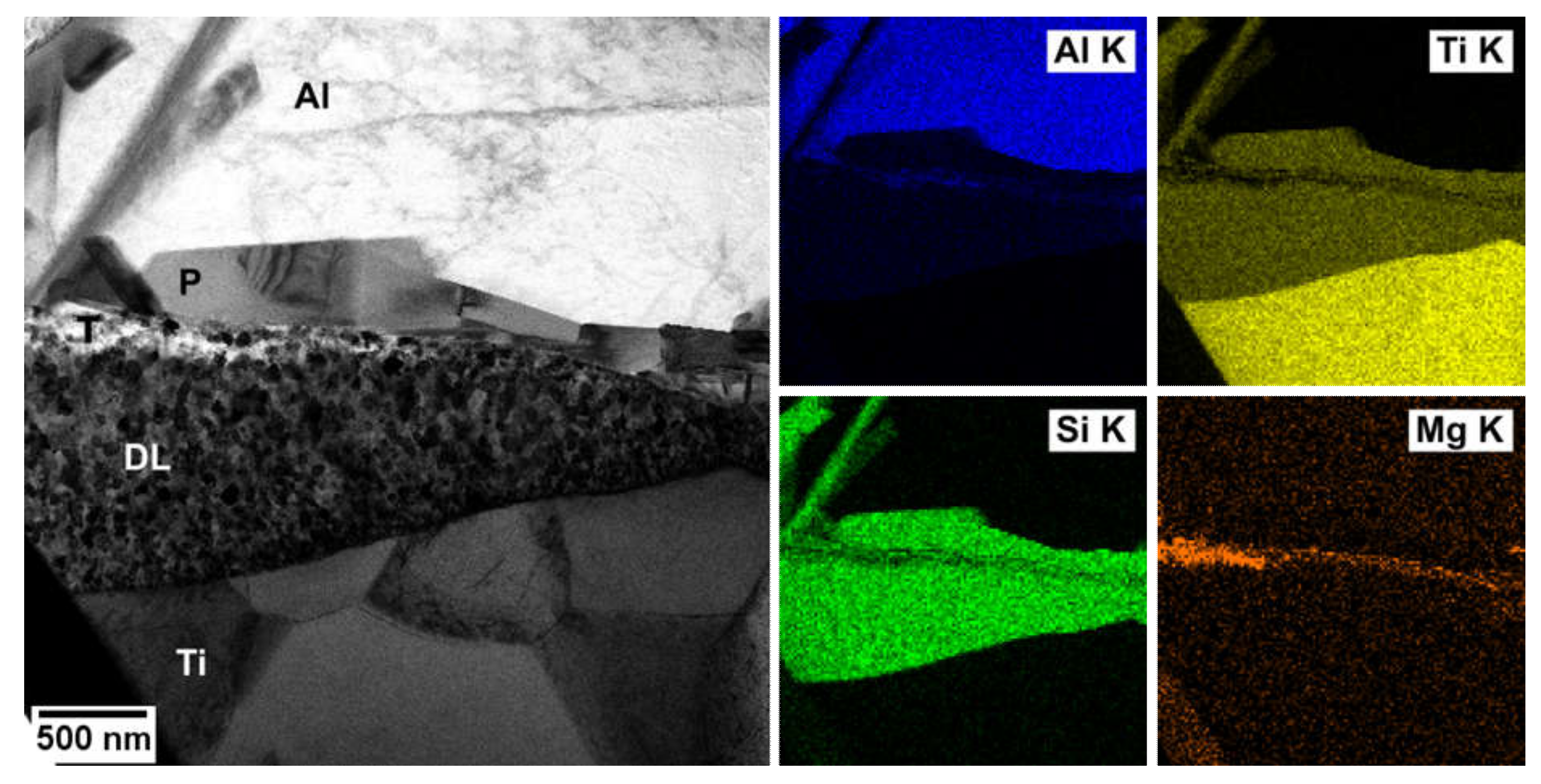
EDS map of the interface (Figure 7) confirms the results obtained using SEM. Both the diffusion layer and the precipitates are ternary phases of Si, Ti and Al, significantly enriched with Si (compared to its overall content), and Mg is segregated at the interface between them. It is also clear that the composition within the diffusion layer and within the precipitates is fairly homogeneous and that there is no significant gradient in the chemical composition near the interface of the phases. This is consistent with the limited solubility of Si in Ti and of Ti in Al.
EDS analysis of the diffusion layer and the precipitates was also performed separately. The three localized measurements are presented in the Table 4, and can be considered identical due to the uncertainty of quantitative estimation of the standardless EDS. The composition corresponds to so-called τ1 and τ2 ternary Al-Si-Ti phases reported with the approximate composition of Al8–20Ti30–50Si40–60 [38], varying with the temperature.
The important crystallographic parameters of both phases are summarized in the Table 5. Both phases have similar a and b lattice parameters, while the c lattice parameter of the τ1 phase is two times higher than that of the τ2 phase.
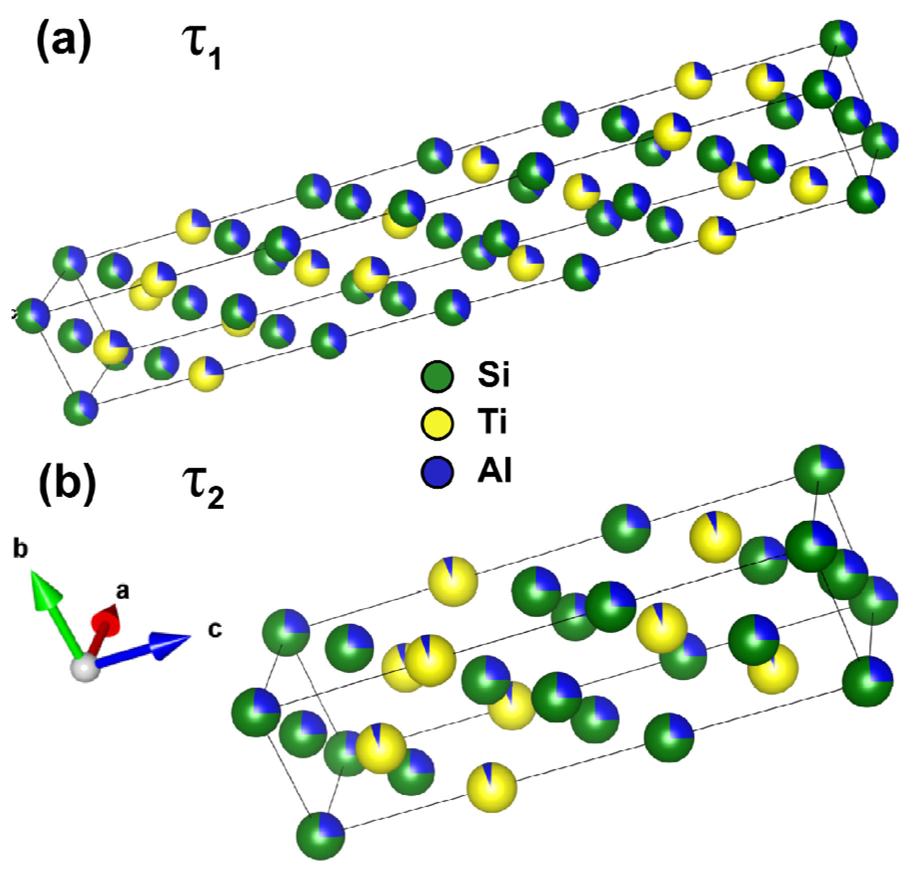
The similarity of both phases is illustrated in Figure 8 with the use of appropriate CIF (Crystallographic Information File). Due to the fact that the CIF of the τ1 phase is not readily available, it was adapted from the CIF of its prototype Zr3Al4Si5—the Zr atoms were replaced by Ti and the lattice parameters were adapted to those reported in [39].
The lattice site occupation by individual elements is not strictly defined, Al atoms can partially replace both Si and Ti atoms in their preferred sites, giving rise to the non-stoichiometry of the phase and the broad range of observed compositions. The τ1 phase is essentially a unit cell of the τ2 phase stacked in the c direction with a few atoms swapped.
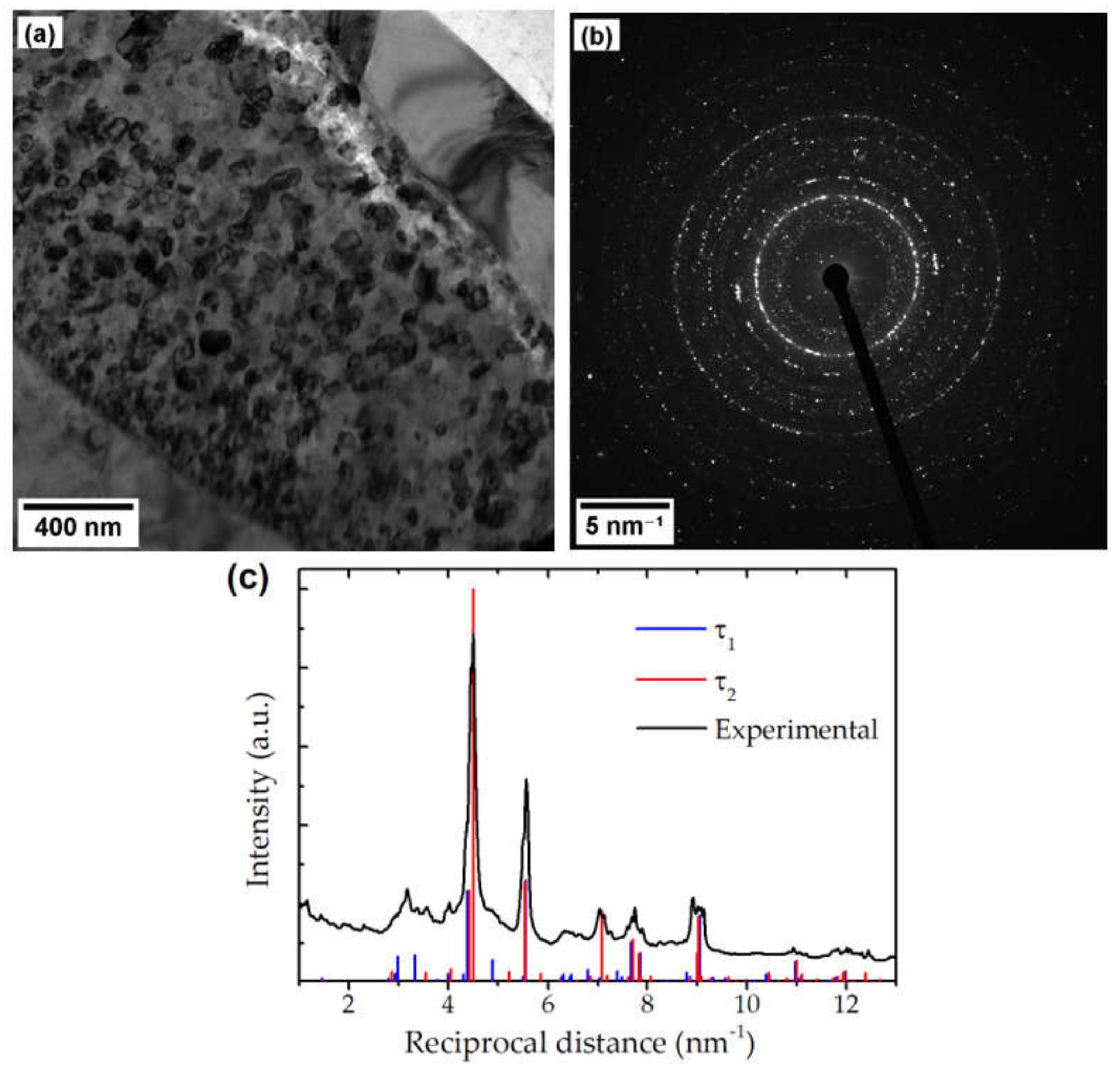
The polycrystalline diffusion layer with the grain size of approximately 100 nm is shown in Figure 9a. EDS mapping showed completely homogeneous composition. The ring SAED pattern is presented in Figure 9b and its radial integration in Figure 9c. Positions of the strongest peaks are consistent with both τ phases (having similar diffraction pattern), while the differences between them are too weak to distinguish unambiguously whether τ1 or τ2 is present in the layer.
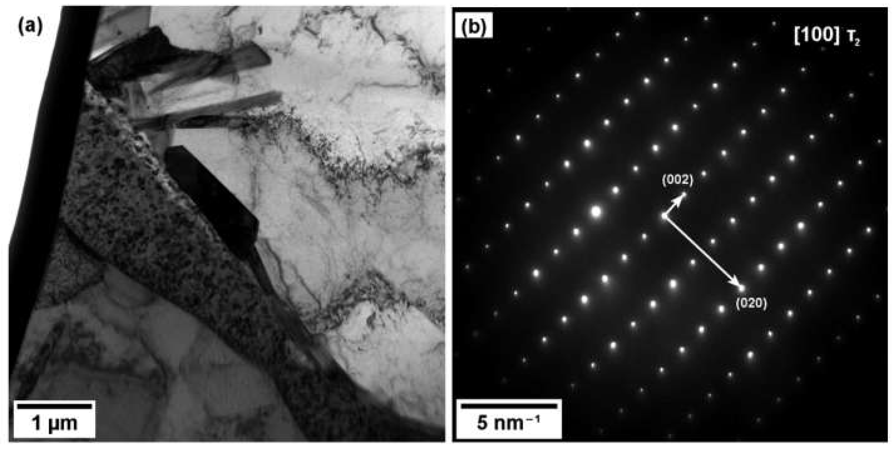
The diffraction pattern of the precipitate P2 (cf. Figure 6b) is shown in Figure 10 and corresponds to the τ2 phase with its long c axis perpendicular to the major axis of the precipitate.
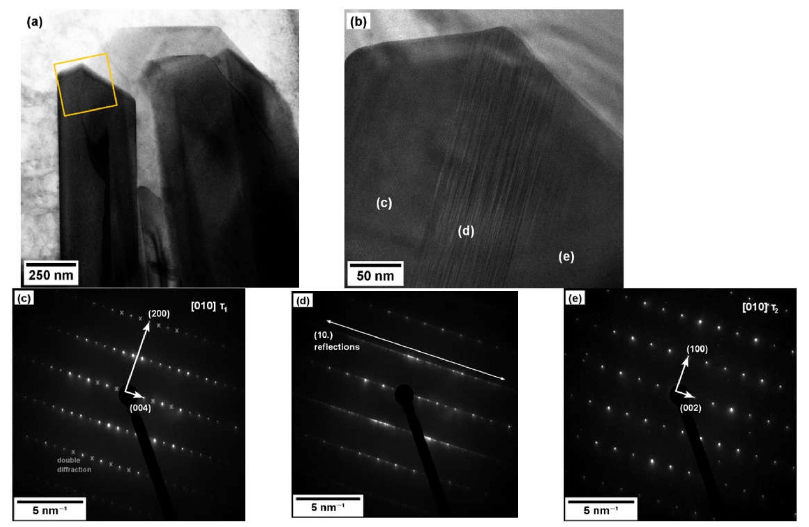
The micrographs of the precipitate P1 (cf. Figure 6b) is presented in Figure 11a,b. The detailed image revealed three different phases in the precipitate, also confirmed by SAED from the respective regions—namely τ1 phase (Figure 11c) at the left side of the precipitate and τ2 at the right side (Figure 11e). Between them, a modulated structure is observed in the micrograph, also manifested by a set of extra diffraction spots of a {10} type. This suggests a complicated or possibly irregular stacking sequence of the τ1/τ2-like unit cells (cf. Figure 8) leading to a great increase in the c lattice parameter of the phase and the extra diffraction spots, while a and b lattice constants are preserved.
4. Discussion
The interface produced between Ti Grade 2 and Al6061 was well developed with no residual porosity and with a continuous layer of intermetallic products. Despite the significant difference in the coefficient of thermal expansion between the two bonded materials, no disjoining was observed at the interface. Rajakumar and Balasubramanian [25] found following optimal parameters for diffusion bonding of Ti Grade 2/Al7075: the temperature of 510 °C, the bonding pressure of 17 MPa and the holding time of 37 min, resulting in a diffusion layer thickness of approximately 7 μm and good mechanical properties. However, the interface composition was not analyzed in detail. The Al7075 alloy contains Cu and Zn, which can lead to the formation of additional intermetallics enhancing the bonding [26]. Wilden [42] reported thinner intermetallic layer (the thickness < 1 μm) after diffusion bonding of Ti Grade 2 and Al6016 (Al-1Si-0.3Mg) alloy at 520 °C and 6 MPa for 60 min. As this temperature is below the Mg2Si solvus temperature (cf. Figure 2), Mg remains inside the precipitates within the Al matrix and does not segregate at the interface. The Mg segregation observed in this work may possibly lead to a decreased interface strength.
The high content of Si in the intermetallic product is not surprising due to the fast inter-diffusion of Si. Significant Si segregation (20 at.%) was already found during friction welding of Ti to Al containing only trace amount of Si (0.12 at.%) in [23].
The τ1 phase was reported in [43] to be the only ternary equilibrium phase in Al-Si-Ti system at 550 °C (after 45 days of annealing), having a composition of Al7.1–13.9Ti33.5–34.2Si51.9–59.1, while only τ2 phase was found after annealing at the same temperature for 132 days [44]. Both ternary τ phases were reported at 700 °C in [38], having slightly different compositions of Al6.2–9.3Ti32.4–34.0Si57.5–60.9 (τ1) and Al10.0–11.6Ti34.2–34.5Si53.9–55.6 (τ2). However, the material studied in this work is not in an equilibrium state after sintering (i.e., not directly comparable) and deviations from the reported equilibrium compositions are possible.
The selection of τ1/τ2 phase during precipitation is probably influenced by the particular diffusion history and minor changes in local concentration. As illustrated in the Figure 8, the two phases are crystallographically similar and back-and-forth transformations, as well as other stacking sequences (cf. Figure 11b,e), are possible. This layered structures resemble so-called long-period stacking order (LPSO) structures, which are observed in Mg-Zn-RE alloys [45], having complicated stacking sequences and creating additional diffraction spots in SAED patterns. Similar long range ordering was recently reported in Ti-Al alloy prepared by direct laser deposition [46]. To our knowledge, such LPSO phase has not been observed in the Al-Si-Ti system yet.
5. Conclusions
The following conclusions can be drawn from this experimental study:
- Heterogeneous composite material was manufactured from Ti Grade 2 bulk and Al6061 alloy powder by FAST at 560 °C for 10 min.
- Diffusion layer is continuous with the thickness of approx. 1–2 µm and consists of ternary Al-Si-Ti τ1 and τ2 phases.
- Si significantly affects the formation of the diffusion layer due to its high inter-diffusion coefficient in Al. Similar diffusion layers in terms of width have been observed after diffusion bonding of Ti and Al alloys.
- TEM analysis showed a modulated τ1/τ2 structure resembling the LPSO phase.
- FAST is capable of manufacturing heterogeneous composites from dissimilar materials.
Author Contributions
Conceptualization, J.K. and J.S.; methodology, J.K.; validation, J.K. and J.V.; formal analysis, J.K..; investigation, J.K and J.V.; resources, J.K., T.C. and M.J.; data curation, J.K.; writing—original draft preparation, J.K. and J.S.; writing—review and editing, J.K., J.S. and M.J.; visualization, J.K.; supervision, J.K. and J.S.; project administration, M.J. and T.C.; funding acquisition, J.K., J.S. and M.J. All authors have read and agreed to the published version of the manuscript.
Funding
This research was funded by Czech Science Foundation under the project No. 19-11275S and by the Charles University Grant Agency, project No. 752119. The partial financial support provided by ERDF under the project No. CZ.02.1.01/0.0/0.0/15 003/0000485 is also gratefully acknowledged.
Conflicts of Interest
The authors declare no conflict of interest. The funders had no role in the design of the study; in the collection, analyses, or interpretation of data; in the writing of the manuscript, or in the decision to publish the results.
References
- Aksit, M.; Altstädt, V. Hybrid Materials-Historical Perspective and Current Trends. COJ Rev. Res. 2020, 2, 17. [Google Scholar]
- Wu, X.; Zhu, Y. Heterogeneous materials: A new class of materials with unprecedented mechanical properties. Mater. Res. Lett. 2017, 5, 527–532. [Google Scholar] [CrossRef]
- Estrin, Y.; Bréchet, Y.; Dunlop, J.; Fratzl, P. (Eds.) Architectured Materials in Nature and Engineering: Archimats; Springer Series in Materials Science; Springer Nature Switzerland AG: Cham, Switzerland, 2019; ISBN 978-3-030-11941-6. [Google Scholar]
- Ashby, M.F.; Bréchet, Y.J.M. Designing hybrid materials. Acta. Mater. 2003, 51, 5801–5821. [Google Scholar] [CrossRef]
- Al-Ketan, O.; Rowshan, R.; Abu Al-Rub, R.K. Topology-mechanical property relationship of 3D printed strut, skeletal, and sheet based periodic metallic cellular materials. Addit. Manuf. 2018, 19, 167–183. [Google Scholar] [CrossRef]
- Savio, G.; Rosso, S.; Meneghello, R.; Concheri, G. Geometric Modeling of Cellular Materials for Additive Manufacturing in Biomedical Field: A Review. Available online: https://www.hindawi.com/journals/abb/2018/1654782/ (accessed on 18 November 2020).
- Schaedler, T.A.; Carter, W.B. Architected Cellular Materials. Annu. Rev. Mater. Res. 2016, 46, 187–210. [Google Scholar] [CrossRef]
- Williams, C.B.; Cochran, J.K.; Rosen, D.W. Additive manufacturing of metallic cellular materials via three-dimensional printing. Int. J. Adv. Manuf. Technol. 2011, 53, 231–239. [Google Scholar] [CrossRef]
- Cakmak, E.; Sridharan, N.; Venkatakrishnan, S.V.; Bilheux, H.Z.; Santodonato, L.J.; Shyam, A.; Babu, S.S. Feasibility Study of Making Metallic Hybrid Materials Using Additive Manufacturing. Metall. Mater. Trans. A 2018, 49, 5035–5041. [Google Scholar] [CrossRef]
- Annamalai, A.R.; Srikanth, M.; Muthuchamy, A.; Acharya, S.; Khisti, A.; Agrawal, D.K.; Jen, C.-P. Spark Plasma Sintering and Characterization of Al-TiB2 Composites. Metals 2020, 10, 1110. [Google Scholar] [CrossRef]
- Firestein, K.L.; Corthay, S.; Steinman, A.E.; Matveev, A.T.; Kovalskii, A.M.; Sukhorukova, I.V.; Golberg, D.; Shtansky, D.V. High-strength aluminum-based composites reinforced with BN, AlB2 and AlN particles fabricated via reactive spark plasma sintering of Al-BN powder mixtures. Mater. Sci. Eng. A 2017, 681, 1–9. [Google Scholar] [CrossRef] [Green Version]
- Pellizzari, M.; Cipolloni, G. Spark Plasma Sintering of Copper Matrix Composites Reinforced with TiB2 Particles. Materials 2020, 13, 2602. [Google Scholar] [CrossRef]
- Sweet, G.A.; Brochu, M.; Hexemer, R.L.; Donaldson, I.W.; Bishop, D.P. Consolidation of aluminum-based metal matrix composites via spark plasma sintering. Mater. Sci. Eng. A 2015, 648, 123–133. [Google Scholar] [CrossRef]
- Martin, G.; Fabrègue, D.; Mercier, F.; Chafino-Aixa, J.-A.; Dendievel, R.; Blandin, J.-J. Coupling electron beam melting and spark plasma sintering: A new processing route for achieving titanium architectured microstructures. Scr. Mater. 2016, 122, 5–9. [Google Scholar] [CrossRef]
- de Lama, M.A.; Balden, M.; Greuner, H.; Höschen, T.; Matejicek, J.; You, J.H. Microstructural stability of spark-plasma-sintered Wf/W composite with zirconia interface coating under high-heat-flux hydrogen beam irradiation. Nucl. Mater. Energy 2017, 13, 74–80. [Google Scholar] [CrossRef]
- Trzaska, Z.; Couret, A.; Monchoux, J.-P. Spark plasma sintering mechanisms at the necks between TiAl powder particles. Acta Mater. 2016, 118, 100–108. [Google Scholar] [CrossRef]
- Trzaska, Z.; Bonnefont, G.; Fantozzi, G.; Monchoux, J.-P. Comparison of densification kinetics of a TiAl powder by spark plasma sintering and hot pressing. Acta Mater. 2017, 135, 1–13. [Google Scholar] [CrossRef] [Green Version]
- Trzaska, Z.; Monchoux, J.-P. Electromigration experiments by spark plasma sintering in the silver–zinc system. J. Alloys Compd. 2015, 635, 142–149. [Google Scholar] [CrossRef]
- Pripanapong, P.; Umeda, J.; Imai, H.; Takahashi, M.; Kondoh, K. Tensile Strength of Ti/Mg Alloys Dissimilar Bonding Material Fabricated by Spark Plasma Sintering. IJEIR 2016, 5, 253–259. [Google Scholar]
- Cooke, K.O.; Atieh, A.M. Current Trends in Dissimilar Diffusion Bonding of Titanium Alloys to Stainless Steels, Aluminium and Magnesium. J. Manuf. Mater. Process. 2020, 4, 39. [Google Scholar] [CrossRef]
- Fuji, A. In situ observation of interlayer growth during heat treatment of friction weld joint between pure titanium and pure aluminium. Sci. Technol. Weld. Join. 2002, 7, 413–416. [Google Scholar] [CrossRef]
- Fuji, A.; Ikeuchi, K.; Sato, Y.S.; Kokawa, H. Interlayer growth at interfaces of Ti/Al–1%Mn, Ti/Al–4·6%Mg and Ti/pure Al friction weld joints by post-weld heat treatment. Sci. Technol. Weld. Join. 2004, 9, 507–512. [Google Scholar] [CrossRef]
- Hamajima, T.; Ameyama, K.; Fuji, A. Microstructural Change of Weld Interface in Ti/Al Friction Weld during Heat Treatment. J. Soc. Mater. Sci. Jpn. 1995, 44, 1224–1230. [Google Scholar] [CrossRef]
- Ma, Z.; Jin, Y.; Ji, S.; Meng, X.; Ma, L.; Li, Q. A general strategy for the reliable joining of Al/Ti dissimilar alloys via ultrasonic assisted friction stir welding. J. Mater. Sci. Technol. 2019, 35, 94–99. [Google Scholar] [CrossRef]
- Rajakumar, S.; Balasubramanian, V. Diffusion bonding of titanium and AA 7075 aluminum alloy dissimilar joints—process modeling and optimization using desirability approach. Int. J. Adv. Manuf. Technol. 2016, 86, 1095–1112. [Google Scholar] [CrossRef]
- AlHazaa, A.; Khan, T.I.; Haq, I. Transient liquid phase (TLP) bonding of Al7075 to Ti–6Al–4V alloy. Mater. Charact. 2010, 61, 312–317. [Google Scholar] [CrossRef]
- ASM Handbook, Volume 2: Properties of Wrought Aluminum and Aluminum Alloys; ASM International: Russel Township, OH, USA, 1990; ISBN 978-1-62708-162-7.
- ASM Handbook, Volume 4: Heat Treating of Aluminum Alloys; ASM Internationa: Russel Township, OH, USA, 1991; Volume 4.
- Welsch, G.; Boyer, R.; Collings, E.W. Materials Properties Handbook: Titanium Alloys; ASM International Russel Township: Russel Township, OH, USA, 1993; ISBN 978-0-87170-481-8. [Google Scholar]
- Al6061-T6, Al6061-T651. Available online: http://asm.matweb.com/search/SpecificMaterial.asp?bassnum=MA6061T6 (accessed on 22 November 2020).
- Zháňal, P.; Václavová, K.; Hadzima, B.; Harcuba, P.; Stráský, J.; Janeček, M.; Polyakova, V.; Semenova, I.; Hájek, M.; Hajizadeh, K. Thermal stability of ultrafine-grained commercial purity Ti and Ti–6Al–7Nb alloy investigated by electrical resistance, microhardness and scanning electron microscopy. Mater. Sci. Eng. A 2016, 651, 886–892. [Google Scholar] [CrossRef]
- Ti Grade 2. Available online: http://asm.matweb.com/search/SpecificMaterial.asp?bassnum=MTU020 (accessed on 22 November 2020).
- Räisänen, J.; Anttila, A.; Keinonen, J. Diffusion of aluminum in ion-implanted α-Ti. J. Appl. Phys. 1985, 57, 613–614. [Google Scholar] [CrossRef]
- Diffusion in Dilute Substitutional Alloys. In Diffusion in Solids: Fundamentals, Methods, Materials, Diffusion-Controlled Processes; Mehrer, H. (Ed.) Springer Series in Solid-State Sciences; Springer: Berlin, Heidelberg, 2007; pp. 327–339. ISBN 978-3-540-71488-0. [Google Scholar]
- Räisänen, J.; Keinonen, J. Annealing behavior of Si in ion-implanted α-Ti. Appl. Phys. Lett. 1986, 49, 773–775. [Google Scholar] [CrossRef]
- Du, Y.; Chang, Y.A.; Huang, B.; Gong, W.; Jin, Z.; Xu, H.; Yuan, Z.; Liu, Y.; He, Y.; Xie, F.-Y. Diffusion coefficients of some solutes in fcc and liquid Al: Critical evaluation and correlation. Mater. Sci. Eng. A 2003, 363, 140–151. [Google Scholar] [CrossRef]
- Murray, J.L. The Mg−Ti (Magnesium-Titanium) system. Bull. Alloy Phase Diagr. 1986, 7, 245–248. [Google Scholar] [CrossRef]
- Li, Z.; Liao, C.; Liu, Y.; Wang, X.; Wu, Y.; Zhao, M.; Long, Z.; Yin, F. 700 °C Isothermal Section of the Al-Ti-Si Ternary Phase Diagram. J. Phase Equilibria Diffus. 2014, 35, 564–574. [Google Scholar] [CrossRef]
- Schubert, K.; Frank, K.; Gohle, R.; Maldonado, A.; Meissner, H.G.; Raman, A.; Rossteutscher, W. Einige Strukturdaten metallischer Phasen (8). Naturwissenschaften 1963, 50, 41. [Google Scholar] [CrossRef]
- Raman, A.; Schubert, K. Über den Aufbau einiger zu TiAl3 verwandter Legierungsreihen. II. Untersuchungen in einigen T-Al-Si- und T4...6-In-Systemen. Z. Für Met. 1965, 56, 44–52. [Google Scholar]
- Momma, K.; Izumi, F. VESTA 3 for three-dimensional visualization of crystal, volumetric and morphology data. J. Appl. Crystallogr. 2011, 44, 1272–1276. [Google Scholar] [CrossRef]
- Wilden, J.; Bergmann, J.P.; Herz, S. Properties of diffusion welded hybrid joints titanium/aluminum. In Proceedings of the 3rd International Brazing and Soldering Conference, San Antonio, TX, USA, 24–26 April 2006; Stephens, J.J., Weil, K.S., Eds.; ASM Int.: Materials Park, OH, USA, 2006; pp. 338–343, ISBN 978-0-87170-838-0. [Google Scholar]
- Wang, J.; Liu, Y.; Liu, Y.; Wu, C.; Su, X. The Isothermal Section of the Al-Si-Ti Ternary System at 550 °C. J. Phase Equilibria Diffus. 2019, 40, 810–819. [Google Scholar] [CrossRef]
- Luo, Q.; Li, Q.; Zhang, J.-Y.; Chen, S.-L.; Chou, K.-C. Experimental investigation and thermodynamic calculation of the Al–Si–Ti system in Al-rich corner. J. Alloys Compd. 2014, 602, 58–65. [Google Scholar] [CrossRef]
- Egusa, D.; Abe, E. The structure of long period stacking/order Mg–Zn–RE phases with extended non-stoichiometry ranges. Acta Mater. 2012, 60, 166–178. [Google Scholar] [CrossRef]
- Zhang, X.; Li, C.; Zheng, M.; Zhong, H.; Gu, J. Alternative-band microstructure and LPSO phase in TiAl alloy produced by direct laser deposition. Mater. Charact. 2020, 164, 110315. [Google Scholar] [CrossRef]
Figure 1.
Cross-sections of (a) Al6061 powder particle, (b) Ti Grade 2 wire with an extrusion direction marked by the arrow.
Figure 1.
Cross-sections of (a) Al6061 powder particle, (b) Ti Grade 2 wire with an extrusion direction marked by the arrow.

Figure 2.
The course of temperature, piston pressure and piston position during the sintering process.
Figure 2.
The course of temperature, piston pressure and piston position during the sintering process.

Figure 3.
Low magnification SEM-BSE micrograph of the cross-section of Ti Grade 2/Al6061 sample, showing titanium wires embedded in the Al6061 matrix. The apparent elipticity is caused by tilting the wire with respect to the specimen surface.
Figure 3.
Low magnification SEM-BSE micrograph of the cross-section of Ti Grade 2/Al6061 sample, showing titanium wires embedded in the Al6061 matrix. The apparent elipticity is caused by tilting the wire with respect to the specimen surface.

Figure 4.
(a) Ti Grade 2/Al6061 interface with a diffusion layer and precipitates in the Al6061 matrix, (b) A detail of the diffusion layer in Ti Grade 2; the precipitates in Al6061 are growing from the diffusion layer.
Figure 4.
(a) Ti Grade 2/Al6061 interface with a diffusion layer and precipitates in the Al6061 matrix, (b) A detail of the diffusion layer in Ti Grade 2; the precipitates in Al6061 are growing from the diffusion layer.

Figure 5.
(a) A detail of the Ti Grade 2/Al6061 interface. (b) A composition profile across the interface with major regions labeled: Ti wire (Ti), Al6061 matrix (Al), diffusion layer (DL), precipitate (P) and transition layer with Mg segregation (T).
Figure 5.
(a) A detail of the Ti Grade 2/Al6061 interface. (b) A composition profile across the interface with major regions labeled: Ti wire (Ti), Al6061 matrix (Al), diffusion layer (DL), precipitate (P) and transition layer with Mg segregation (T).

Figure 6.
(a) Lamella position on the interface. (b) The finished lamella showing the interface cross-section. The diffusion layer (DL) and the precipitates (P1 and P2) investigated further by the TEM (see below) are marked.
Figure 6.
(a) Lamella position on the interface. (b) The finished lamella showing the interface cross-section. The diffusion layer (DL) and the precipitates (P1 and P2) investigated further by the TEM (see below) are marked.

Figure 7.
EDS map of the interface with precipitates and the diffusion layer. The concentrations of Al, Ti and Si are fairly homogeneous within each phase. Mg is segregated between the diffusion layer and the precipitate. The labels correspond to those in the Figure 5.
Figure 7.
EDS map of the interface with precipitates and the diffusion layer. The concentrations of Al, Ti and Si are fairly homogeneous within each phase. Mg is segregated between the diffusion layer and the precipitate. The labels correspond to those in the Figure 5.

Figure 8.
Unit cells of the (a) τ1 and (b) τ2 phase. The τ1 phase is adapted from its prototype Zr3Al4Si5. Coloring of individual atoms represent relative occupancies according to the CIFs (crystallographic information files). Visualizations were prepared using the VESTA software [41].
Figure 8.
Unit cells of the (a) τ1 and (b) τ2 phase. The τ1 phase is adapted from its prototype Zr3Al4Si5. Coloring of individual atoms represent relative occupancies according to the CIFs (crystallographic information files). Visualizations were prepared using the VESTA software [41].

Figure 9.
(a) BF TEM micrograph of the diffusion layer. (b) Corresponding powder diffraction rings of the diffusion layer. (c) Radially integrated experimental profile (b) with the theoretical positions of the τ1 and τ2 lines. The height of the line corresponds to its relative intensity.
Figure 9.
(a) BF TEM micrograph of the diffusion layer. (b) Corresponding powder diffraction rings of the diffusion layer. (c) Radially integrated experimental profile (b) with the theoretical positions of the τ1 and τ2 lines. The height of the line corresponds to its relative intensity.

Figure 10.
(a) BF TEM micrograph of the precipitate at the interface. (b) SAED of the dark particle in (a) corresponding to the τ2 phase in [100] direction.
Figure 10.
(a) BF TEM micrograph of the precipitate at the interface. (b) SAED of the dark particle in (a) corresponding to the τ2 phase in [100] direction.

Figure 11.
(a) BF STEM micrograph of the precipitate at the interface. (b) Detail of the precipitate (marked in (a)) having three different crystal structures. (c) SAED from the left side of the particle in (b) corresponding to the τ1 phase in [010] direction. Double diffractions are marked by grey crosses. (d) SAED from the central region of (b) with a complicated stacking sequence along c axis, creating extra {10} type reflections (blending into streaks). (e) SAED from the right side of the particle in (b) corresponding to the τ2 phase in [010] direction.


Table 1.
The chemical composition of Al6061 alloy according to the supplier.
| Element | Si | Mg | Fe | Cu | Cr | Ti | Mn | Zn | Al |
|---|---|---|---|---|---|---|---|---|---|
| wt.% | 0.75 | 0.93 | 0.30 | 0.33 | 0.21 | 0.01 | 0.05 | <0.002 | bal. |
| at.% | 0.72 | 1.04 | 0.15 | 0.14 | 0.11 | 0.01 | 0.02 | <0.001 | bal. |
Table 2.
Vickers microhardness of the sintered components.
| Material | Al6061 | Ti Grade 2 |
|---|---|---|
| Microhardness (HV0.5) | 57 ± 2 | 128 ± 3 |
Table 3.
Diffusion properties of the elements at the sintering temperature. Diffusion coefficients D and diffusion lengths () are shown for the diffusion of Al and Si into Ti and for Ti and V into Al. The values were calculated for T = 560 °C, t = 600 s (isothermal part of the sintering program).
Table 3.
Diffusion properties of the elements at the sintering temperature. Diffusion coefficients D and diffusion lengths () are shown for the diffusion of Al and Si into Ti and for Ti and V into Al. The values were calculated for T = 560 °C, t = 600 s (isothermal part of the sintering program).
| In α Titanium | In Aluminium | ||||||
|---|---|---|---|---|---|---|---|
| D (m2/s) | L (nm) | Reference | D (m2/s) | L (nm) | Reference | ||
| Al | 1.17 × 10⁻²⁰ | 3 | [33] | Ti | 5.69 × 10⁻¹³ | 58 | [34] |
| Si | 1.12 × 10⁻¹⁷ | 82 | [35] | Si | 5.84 × 10⁻¹³ | 1.9 × 10⁴ | [36] |
| Mg | insoluble | - | [20,37] | Mg | 4.15 × 10⁻¹³ | 1.5 × 10⁴ | [36] |
Table 4.
EDS analysis of the diffusion layer and individual powder particles, labels correspond to the labels in Figure 6b. The data are qualitative in nature.
Table 4.
EDS analysis of the diffusion layer and individual powder particles, labels correspond to the labels in Figure 6b. The data are qualitative in nature.
| Analyzed Region | Mg (at.%) | Al (at.%) | Si (at.%) | Ti (at.%) |
|---|---|---|---|---|
| Diffusion layer (DL) | 0.07 | 10.1 | 47.5 | 42.4 |
| Precipitate 1 (P1) | 0.07 | 9.5 | 38.1 | 52.4 |
| Precipitate 2 (P2) | 0.08 | 12.2 | 46.9 | 40.9 |
Publisher’s Note: MDPI stays neutral with regard to jurisdictional claims in published maps and institutional affiliations. |
© 2020 by the authors. Licensee MDPI, Basel, Switzerland. This article is an open access article distributed under the terms and conditions of the Creative Commons Attribution (CC BY) license (http://creativecommons.org/licenses/by/4.0/).
Share and Cite
MDPI and ACS Style
Kozlík, J.; Veselý, J.; Stráský, J.; Chráska, T.; Janeček, M. Interface of a Al6061/Ti Composite Prepared by Field Assisted Sintering Technique. Metals 2021, 11, 73. https://doi.org/10.3390/met11010073
AMA Style
Kozlík J, Veselý J, Stráský J, Chráska T, Janeček M. Interface of a Al6061/Ti Composite Prepared by Field Assisted Sintering Technique. Metals. 2021; 11(1):73. https://doi.org/10.3390/met11010073
Chicago/Turabian StyleKozlík, Jiří, Jozef Veselý, Josef Stráský, Tomáš Chráska, and Miloš Janeček. 2021. "Interface of a Al6061/Ti Composite Prepared by Field Assisted Sintering Technique" Metals 11, no. 1: 73. https://doi.org/10.3390/met11010073
Note that from the first issue of 2016, this journal uses article numbers instead of page numbers. See further details here.