High Cycle Fatigue Data Transferability of MAR-M 247 Superalloy from Separately Cast Specimens to Real Gas Turbine Blade


1
Institute of Physics of Materials, Czech Academy of Sciences, Žižkova 22, 616 62 Brno, Czech Republic
2
CEITEC IPM, Žižkova 22, 616 62 Brno, Czech Republic
3
PBS Velká Bíteš a.s., Vlkovská 279, 595 12 Velká Bíteš, Czech Republic
*
Author to whom correspondence should be addressed.
Metals 2020, 10(11), 1460; https://doi.org/10.3390/met10111460
Submission received: 17 September 2020
/
Revised: 27 October 2020
/
Accepted: 29 October 2020
/
Published: 31 October 2020
(This article belongs to the Special Issue Fracture, Fatigue, and Structural Integrity of Metallic Materials and Components Undergoing Random or Variable Amplitude Loadings)
Abstract
:Cast polycrystalline superalloys are widely used for critical components in aerospace and automotive industries, such as turbine blades or turbocharges. Therefore, their fatigue endurance belongs to one of the most essential mechanical characteristics. Full-scale testing of such components involves great technical difficulties and requires significant experimental effort. The present study evaluates the effects of microstructural parameters with respect to representative fatigue testing of a cast turbine blade by separately cast specimens. For that purpose, the cast polycrystalline MAR-M 247 Ni-based superalloy was investigated in the following conditions: (i) specimens extracted from a real gas turbine blade; specimens separately cast into the mould with (ii) top or (iii) bottom filling systems. Obtained diverse microstructures allowed us to assess the effect of grain size, porosity, and texture on fatigue performance. The tests were held at a symmetrical loading regime at temperature 800 °C in laboratory air. The results indicate that the level of porosity is a dominant structural parameter determining the fatigue endurance, while grain size and texture effects were of minor importance contributing mainly to fatigue life scatter.
1. Introduction
Nickel-based superalloys are a vast class of the materials, essential for the aerospace, automotive, and power generation industry, which are recognized for an excellent combination of strength, structural stability at high temperatures, and very good corrosion resistance. Although single-crystal superalloys are used in modern gas turbines or jet engines, polycrystalline investment cast superalloy blades still find a wide array of applications thanks to less demanding fabrication processes and better affordability. Therefore, the investigation of fatigue performance and the effect of the structural imperfections naturally inherited by casting technologies still attracts interest [1,2,3].
Before the integration of a blade into a turbine, the assessment of design and fatigue endurance is essential and of great interest for aerospace and power generation industries. These components experience severe service conditions comprising mechanical loading (low and high cycle fatigue, creep), high temperatures, and corrosion environments, which may result in catastrophic failure. Since the geometrical complexity of the blades inevitably presents locally different casting conditions, such as temperature gradient and solidifications rate, the microstructure of various sections can differ significantly [4]. These variations are reflected by the diversity in grain size, primary and secondary dendritic arm spacing, distribution and size of carbides, shrinkages, and gas pores. Microstructural deviations result in locally dependent susceptibility to failure by different loading conditions within a blade. For instance, high cycle fatigue (HCF) damage processes are very localized and susceptible to local stress concentrators such as shrinkages and gas pores [5,6]. Contrary to that, creep and low cycle fatigue (LCF) damage mechanisms are affected by other microstructural aspects such as the distribution and the size of brittle phases [7,8], topologically close-packed phases, and γ/γ’ eutectics [9]. Moreover, the microstructures with various phase constituents accommodate plastic deformation in a different manner reflected by different crack initiation and propagation mechanisms [2]. Therefore, the relationship of processing technology–microstructure–mechanical properties at severe service conditions possesses a high level of complexity and represents the important subject of an intensive effort for academia and industry.
Isothermal mechanical testing provides an essential experimental data for the determination of expected total operational lifetime of a turbine blade. Moreover, mechanical testing is essential for the maintenance interval optimization, which presents cost- and time-wise undesirable shut-downs. One of the possible approaches for fatigue and creep tests is the utilization of real full-scale blades. An undeniable advantage is that test blades undergo the identical manufacturing processes and possess the same microstructure and dimensions as the blade utilized in a real turbine. However, full-scale experiments are financially very demanding, time-consuming, and require a unique laboratory facility [1,10,11]. Another setback of such an approach is the inability to isolate the individual effects of various mechanical loadings, which makes the experimental data analysis difficult. Therefore, the finite element (FE) and crystal plasticity modelling [12] of turbine blades under various loading conditions is regarded as an important supplementary approach to analyse such complex engineering challenges [1,13,14,15]. Experimental results carried out on small-scale specimens extracted from various blade sections can be utilized as a data input or a verification basis of the models. This approach can bring a better understanding of mechanical property variations with respect to local microstructure and texture heterogeneity stemming from different solidification conditions [16,17,18]. A few small-scale specimen studies [19,20] were carried out in the past and have shown their worthiness by presenting significant dependence of the fatigue endurance, hardness, and tensile properties on a blade section.
The present study aims to highlight the important factors of high-temperature fatigue testing within the framework of the HCF performance assessment of a gas turbine blade. The fatigue tests were carried out using fatigue specimens produced by two casting processes varying in different mould filling setups. Acquired microstructures and related fatigue life are discussed and compared with the fatigue performance of the specimens extracted from three locations of a gas turbine blade.
2. Materials and Methods
The cast polycrystalline MAR-M 247 superalloy, provided by the company PBS Velká Bíteš, a.s., was processed by investment casting in three variants: (i) real blade casting, (ii) casting of semi-finished specimens by a mould with top filling (further entitled as TF), and (iii) with bottom filling (BF). Figure 1 shows the schematics with the highlighted flow of the molten metal during the casting. Different moulds were utilized in order to obtain various microstructures and to minimize porosity: eight cylindrical bars in an approximate shape of fatigue test specimens were attached to the top (Figure 1b) or the bottom radial running system (Figure 1c). The BF mould also contained the TF system, which was left just as a reinforcement to ease the handling. The casting was performed under vacuum 10−4 Pa, whereas pouring temperature was 1385 ± 15 °C and mould temperature was 1050 °C. After the end of solidification, the bars were extracted from the pattern and subsequently underwent hot isostatic pressing (HIP) procedure (1200 °C/4 h/100 MPa/argon) and two-step heat treatment consisting of a solution annealing at 1200 °C/2 h/air cooling followed by a precipitation annealing at 870 °C/24 h/air cooling. Several bars cast by the TF mould were left without HIP to assess the effect of this process on the porosity and resulting fatigue life. Subsequently, the semi-finished specimens were machined into final specimen geometry.
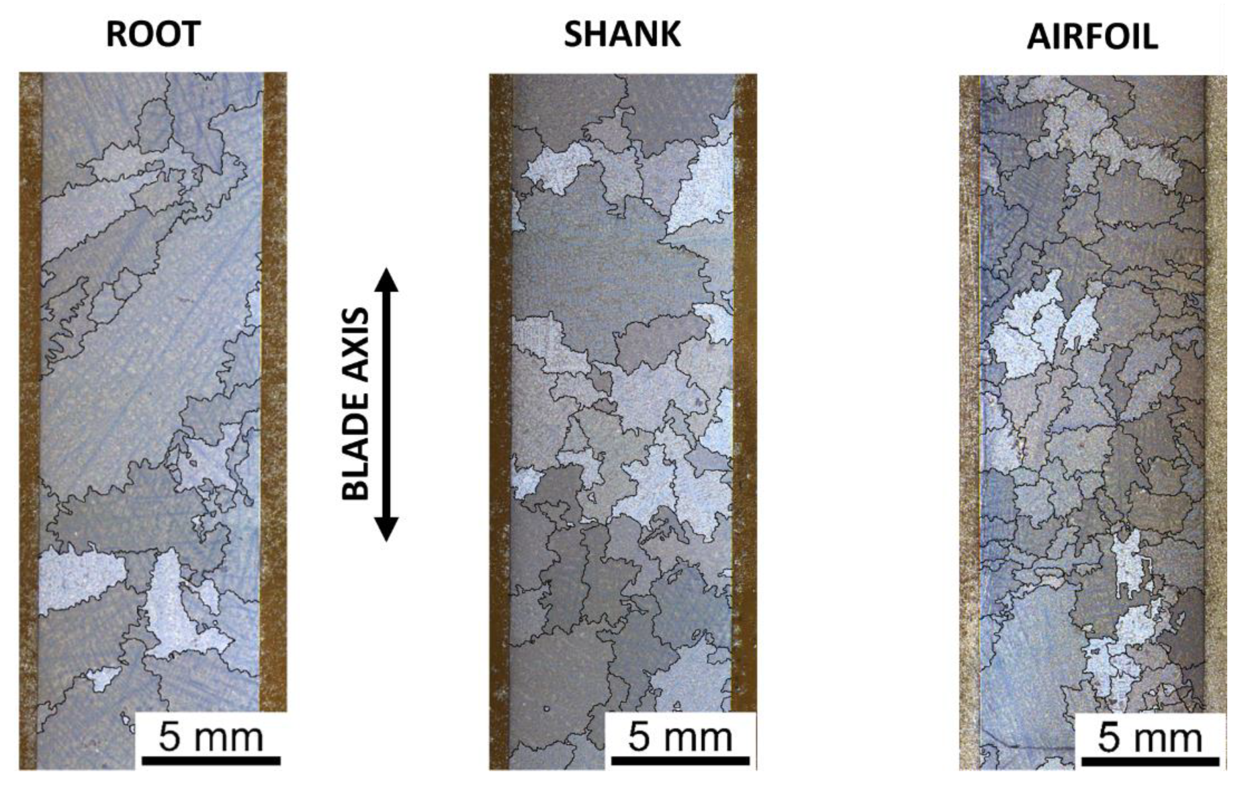
Besides the mould castings, the cylindrical bars dedicated for fatigue specimen fabrication were extracted by electrical discharge machining from three sections of the blade—further referred to as root, shank, and airfoil. From the reason of insufficient cross-blade dimensions, it was not possible to acquire specimens from the airfoil above cross-section III. The positions of bar extraction are depicted in Figure 2a and specimen geometry in Figure 2b. Due to complex geometry, the microstructure of the blade varied significantly. To examine this microstructural diversity, large-scale metallographic samples were prepared. The positions of sectioning, labelled I–IV, are depicted in Figure 2a, and the sample micrographs are shown in Figure S1 (available in the Supplementary Materials).
A resonant testing machine Amsler with 100 kN force range was used for fatigue tests under load control regime in fully reversed loading (R = −1). The fatigue tests were performed at frequency 121 ± 2 Hz in laboratory air. The experimental temperature 800 °C was achieved by an electric furnace with resistance heating. The tests were terminated, while the loading frequency decreased by 5 Hz or in the case of specimen rupture. Fatigue limit, σf, was defined as a stress amplitude value at which a minimum of three specimens reached 2 × 10⁷ cycles without failure.
The metallographic sections of blade, perpendicular to blade axis, and the sections of fatigued specimens, cut longitudinal to the loading direction, were carefully ground by sandpapers with increasing grit number and subsequently polished by 1 µm diamond paste. The final chemical–mechanical polishing by colloidal silica slurry provided the surface quality sufficient for the electron backscatter diffraction (EBSD) measurement. Etching by a solution of 100 mL H2O, 4 mL HNO3, and 2 mL HF was used to reveal grain boundaries. Initial light microscopic (LM) analysis was performed using a stereomicroscope Leica S9i, whereas fracture surfaces and longitudinal sections were observed by a scanning electron microscope (SEM) Tescan LYRA 3 XMU (Tescan Orsay Holding, a.s., Brno, Czech Republic). The EBSD observations were performed with an electron beam operating at 20 kV by a NordlysNano EBSD camera (Oxford Instruments, Abingdon, UK). The EBSD data were analysed by the CHANNEL 5 software (Oxford Instruments, Abingdon, UK). Secondary dendritic arm spacing (SDAS) measurement were performed by light microscope Olympus GX51 (Olympus, Tokyo, Japan) on polished and etched metallographic samples. For that purpose, the linear intercept method was employed, and presented values are the result of 60 measurements for each alloy variant.
Nominal chemical composition of the MAR-M 247 superalloy is given in Table 1. The alloy has a typical cast structure with coarse dendritic grains of average size ranging between hundreds of microns and a few millimetres. The microstructure, see Figure 3, contains strengthening coherent precipitates of γ’ phase heterogeneously distributed in γ matrix. Areas of fine γ’ phase with cuboidal shape (~0.4 μm) and areas of coarse γ’ phase with more complicated morphology (~1.6 μm in diameter) were present. The investigations of Harris et al. [21] and Janowski [22] revealed the volume fraction of γ’ phase of approximately 60%. Numerous carbides and γ/γ’ eutectics were located along grain boundaries and interdendritic areas.
3. Results
3.1. Microstructural Characterization
Microstructures in the gauge part of the specimens extracted from all three blade positions are shown in Figure 4. Corresponding average grain size and secondary dendrite arm spacing (SDAS) are given in Table 2. Since grain size strongly varies, minimum and maximum values are also included. The significant scatter of grain size among the blade positions stems from the variations in local blade thickness and geometry. The root of the blade consists of large equiaxed grains owing to bulky character of the section resulting from slow solidification of the melt. The shank section consisted of distinctly finer dendritic structure. Further grain refinement was observed in the lower part of the airfoil. Since the specimens were fabricated from rather thick parts of the blade, equiaxed grains were dominant over columnar grains. In summary, distinct grain size refinement in the direction of the blade axis towards the blade tip is associated with the local blade thickness. This fact is also reflected by the decrease in the SDAS parameter, which is, together with the primary dendritic arms spacing, proportionally related to the temperature gradient G and the growth rate of the solidification front υ represented by the following equation [23]:
λ1 ≈ υ−1/4 G−1/2.
Therefore, it can be assumed that the bulky blade positions solidify by lower rates, resulting in coarse grain structure with large SDAS, whereas the slender parts of the blade airfoil undergo faster solidification leading to finer dendritic microstructure and lower SDAS.
Figure 5 shows the structures of the TF mould cast specimens (TF specimens) without or with subsequent HIP processing and the BF mould cast specimens (BF specimens). Microstructural characterization was performed on metallographic samples from the specimen gauge cut parallel to the specimen axis. Utilized mould filling setups resulted in different structures in terms of grain size, grain columnarity, and porosity. As shown in Table 2, the average grain size of the BF specimens was notably larger as well as grain size scatter and SDAS parameter. These findings distinctly indicate that BF casting microstructure stems from the slower solidification due to the additional bottom radial running system, which adds a significant molten metal mass. Columnar grain structure was found within the TF specimens. Any distinct effect of the HIP on grain size was not found, which complies well with available literature [24,25].
The porosity assessment was carried out on the fracture surfaces of all fatigued specimens based on the assumption that the primary fatigue crack originates from the most serious structural defect of the specimen gauge. This assumption is deemed to be generally valid for HCF loading regime known for high sensitivity on structural imperfections and essential effect on the fatigue crack initiation [26,27]. The examination of fracture surfaces revealed that the BF specimens exhibited low porosity level with isolated pores in size range 30–70 µm, whereas the TF mould casting resulted in the microstructure containing the shrinkages with the average size 770 µm. The effect of the HIP process, evaluated on a series of the TF specimens left without this treatment, was found to be essential. Shrinkages and pore clusters of average size 3040 µm were found. The analysis of the blades in each position revealed fine pores; therefore, it can be concluded that, with respect to typical grain size observed in each of the blade sections, the porosity was negligible. The principal defects of each tested specimen characterized by Feret diameter are shown further in Figure 8 of Section 3.2.
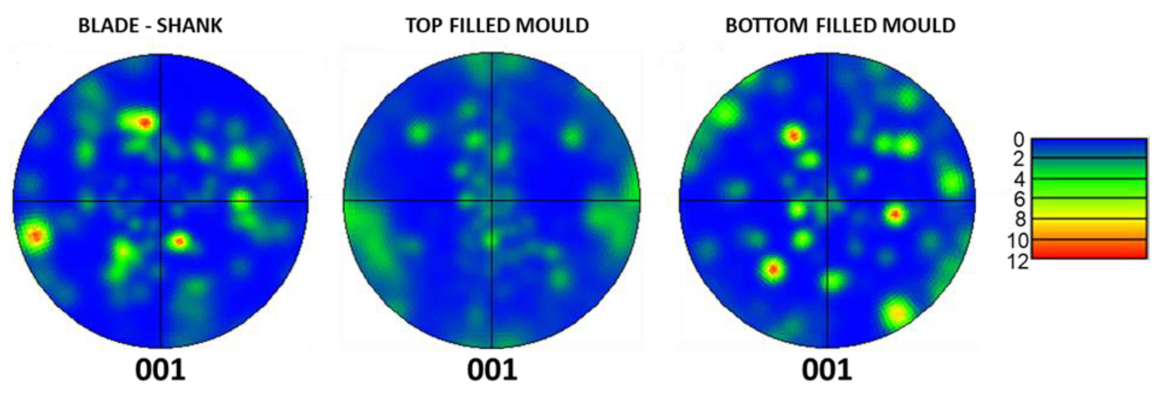
The texture analysis of the blade shank section and both filling systems are shown in Figure 6. The pole figures acquired by the EBSD measurement were performed over a large area of the specimen gauge section depicted in Figure 5. High intensities within corresponding {001} pole figures were caused by coarse microstructures where individual grains cover a significant area fraction of an EBSD map. This is especially distinct in the case of the blade shank, which possessed the largest grain size within the examined microstructures. Despite this fact, any preferential grain orientation was not found.
In summary, the microstructures of specimens cast by three casting setups resulted in distinct differences in grain size and porosity, while the random texture of grains was retained.
3.2. Fatigue Life
Stress-life (S-N) data from the fatigue tests carried out on the specimens originating from three blade positions are shown in Figure 7. Despite distinct microstructural variation among individual positions (see Figure 4), the results indicate a negligible effect of the grain size on HCF performance. Therefore, all experimental data are fitted by a single fatigue life curve, and a fatigue limit of 230 MPa was identified for the blade regardless of the specimen position. In contrast to the similarities of the HCF performance, the scatter of fatigue data varies among the blade positions. Figure 7 indicates that the highest scatter is observed for the airfoil, the section possessing the finest microstructure. It is important to note that a limited number of tests was performed for the airfoil section, since only one specimen could be extracted per blade. Therefore, the experimental data for this particular section are not fully statistically sound in terms of fatigue performance assessment but can give sufficient insight into observed significant fatigue life scatter. Microstructural examinations of several specimen gauge sections revealed that the airfoil part of a blade is sensitive on inevitable fluctuations in casting conditions and in the solidification process. The occasional occurrence of individual coarse grains was confirmed in several specimens. Such microstructural variations can be the source of this fatigue data scatter.
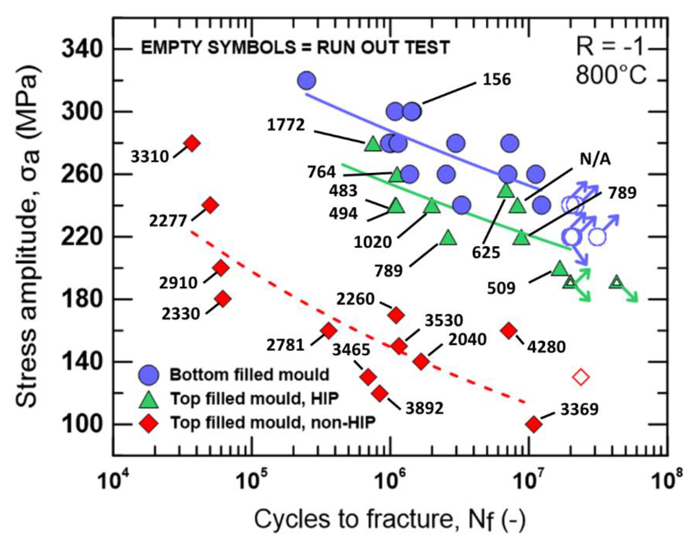
The fatigue life curves of the specimens cast into the TF and the BF moulds are plotted in Figure 8. The diagram includes Feret diameter measurements of the casting defects detected on the fracture surface of each specimen and which were responsible for the fatigue crack initiation. The specimens with no apparent pores or shrinkages to trigger the fatigue crack initiation are the data points without number, which was a domain for the BF specimens. Metallographic samples and fracture surfaces of this casting variant revealed a low level of porosity with isolated gas pores and rare shrinkages. SEM fractographs of typical fracture surfaces for specimen variants is shown in Figure S2 (available in Supplementary Materials). Corresponding fatigue life curves show distinct differences, which directly correspond with the degree of porosity. The castings with a lower content of microstructural defects exhibit better HCF performance. The results reflect the positive effect of the BF pattern casting. Even larger influence than type of the filling system can be attributed to the HIP treatment, which resulted in fatigue life enhancement by more than two orders. Contrarily, the structure without HIP manifests the HCF performance of the alloy with initial shrinkages and gas pores created during solidification. With respect to the Feret diameter of the casting defects, the gauge area cross section is severely reduced leading to increased local peak stresses compared to applied macroscopic stress. Therefore, the fatigue crack initiation within favourably oriented grains adjacent to a large shrinkage is significantly accelerated as well as crack propagation, displayed clearly by strong fatigue life reduction. Fatigue limits were measured just for the HIPed alloy variants. The BF mould casting provides the fatigue limit by 30 MPa higher compared to 190 MPa of the TF mould casting. In summary, Figure 8 demonstrates the dominant effect of the porosity on HCF performance.
3.3. Fractographic Analysis
Figure 9, Figure 10 and Figure 11 show micrograph compilations of selected failed specimens representing each casting variant. A fracture surface with a detail of the crack initiation site and an EBSD map of the grains in the fracture surface vicinity are depicted. The EBSD analysis was carried out on longitudinal sections of specimen gauge, which were cut to intersect the crack initiation site. The sectioning is highlighted by a yellow dashed line in each figure.
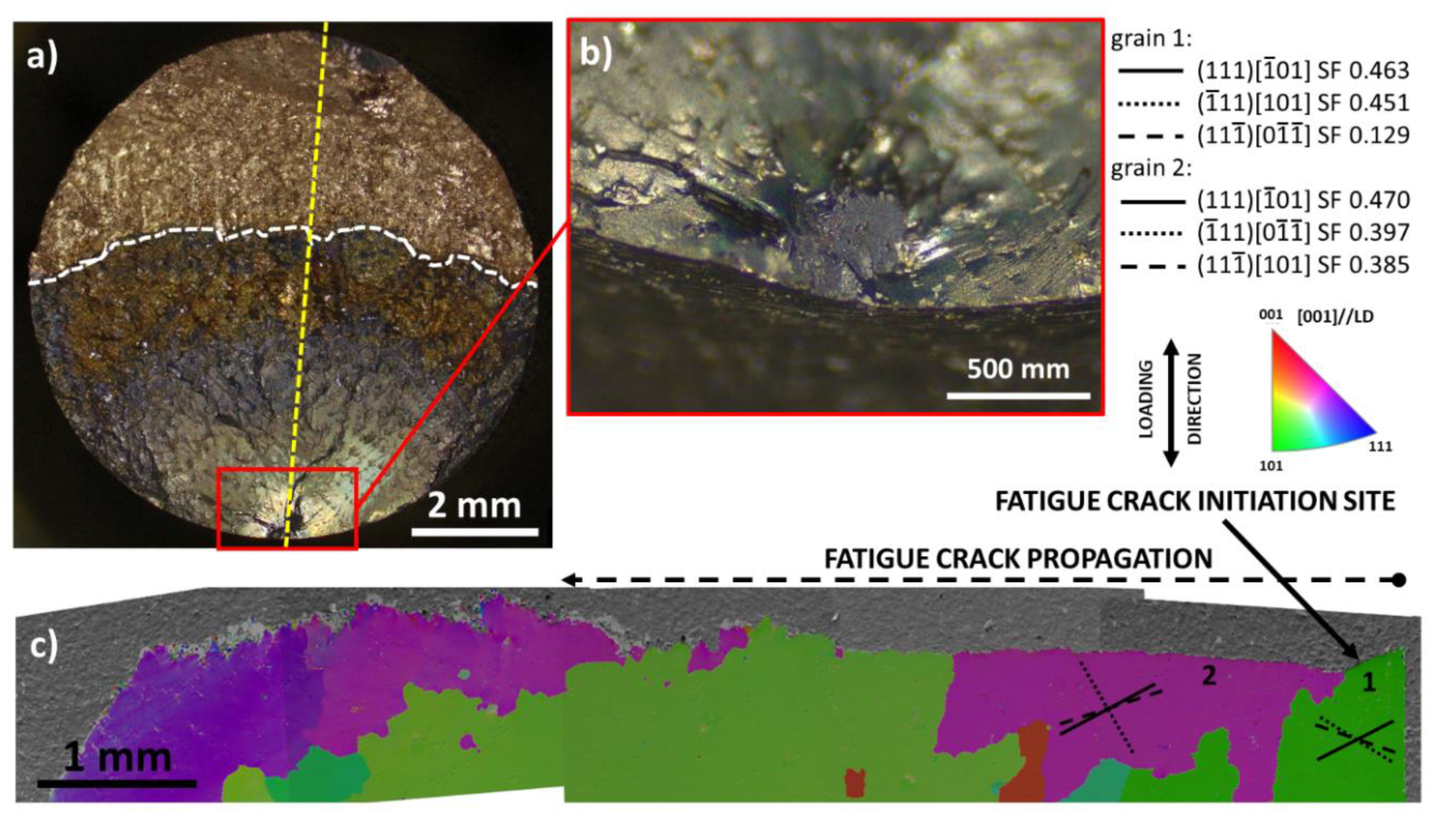
Figure 9 depicts the fracture surface of the TF HIP treated specimen. LM fractography, Figure 9a, revealed complex shrinkage in the sample interior identified as the crack initiation site. Large facets belonging to a single grain, namely grain 2, was found in the vicinity of the crack initiation site shown in Figure 9b. The early stage of the fatigue crack propagation without oxidation assistance is clearly visible as an area with markedly different fracture surface appearance, so-called “fish-eye”, highlighted by the light blue dashed line. The further crack propagation until failure (white dashed line highlight) was characterized by pronounced fracture surface roughness closely related to the dendritic character of the microstructure. Carbide particles, γ/γ′ eutectics and small pores were found on the fracture surface in this area indicating interdendritic crack propagation, see Figure S3 (available in Supplementary Materials). Slip trace analysis, Figure 9c, confirmed that the facet in the place of fatigue crack initiation was of a crystallographic nature, namely the slip plane of type {111} with the highest Schmid factor (SF). The cyclic loading forced the crack initiation along the slip plane with subsequent crack propagation in crystallographic stage I mode until the grain boundary with grain 1 was reached. Therefore, it can be assumed that the stress concentrations induced by the complex shrinkage promoted slip activity along the most suitably oriented slip plane of grain 2. The cyclic loading forced the crack initiation along the slip plane with subsequent crack propagation in crystallographic stage I mode until the grain boundary with grain 1 was reached. Afterwards, the crack driving energy was high enough to propagate further by non-crystallographic stage II mode via structurally weak spots such as carbides and γ/γ′ eutectics. The slip trace analysis of grains 1 and 3 confirmed that the crack did not follow the high SF slip planes, i.e., non-crystallographic crack propagation was active.
As noted in the previous section, the porosity level dropped significantly by using the BF casting setup. As a result, the crack initiation was frequently observed along the favourably oriented slip systems of large grains, without distinct effect of porosity, and from the specimen surface. However, Figure 10 depicts fractographic analysis of the only crack initiation from the pore agglomeration documented in the BF mould castings. Due to suitable grain 1 orientation, the pores were capable of introducing cyclic slip activity on the slip plane with the highest SF. The crack initiation and early crack propagation were under crystallographic stage I mode, while the character of the fracture surface in grains 1 and 3 indicate a transition to non-crystallographic stage II mode. The fish-eye feature is again apparent on the fracture surface indicating oxidation unassisted crack propagation.
The notably different appearance of the fracture surface is presented for the failed specimen of the blade shank part. Since the porosity was nearly absent in the blade castings, the surface crack initiation was predominantly observed. The small facet within the grain 1, shown in Figure 11b, was identified as the fatigue crack initiation site. The crystallographic crack propagation was active only in grain 1. The fracture surface roughness, Figure 11c, gradually increased with the crack length in the same manner for TF and BF specimens. That indicates that the crack path led via fatigue weak areas such as interdendritic areas, as it was already documented by Figure S3 (available in Supplementary Materials).
4. Discussion
Small-scale fatigue specimens testing with the aim to characterize the fatigue performance of a real blade has been studied in the works of Yan et al. [20,28]. Attention was predominantly focused on the influence of specific blade geometry features and the local stress gradients on HCF and LCF life. However microstructural variability was not considered. The present study is focused on the microstructural characterization enabling subsequent evaluation of the dominant structural parameters affecting HCF, such as grain size, texture, and porosity. For that purpose, the fatigue specimens were prepared by two different mould filling setups in order to obtain diverse microstructures. In parallel, the additional set of specimens was extracted from the gas turbine blade in three positions, as it has been presented in Section 2.
The fatigue performance of the material extracted from all blade positions (shown in Figure 7) was similar; however, the fatigue life scatter exhibits variations, especially in the airfoil. The microstructure of this blade position consisted of finer dendritic grains with the occasional appearance of individual coarse grain. Since the level of porosity was negligible in the blade castings, coarse dendritic grains act as a fatigue hot spots where the cyclic deformation mechanisms were facilitated and subsequently a fatigue crack initiation can occur, as it has been described by Miao et al. [29]. The planar character of the cyclic plasticity, typical for superalloys even at a wide range of temperatures as shown by Šulák et al. [30], benefits from coarse grains in terms of dislocation slip activity along feasible crystallographic planes over long distances, uninterrupted by grain boundaries. Moreover, the damage mechanisms can be further accelerated by the occurrence of stress concentrators such as carbides and fine gas pores [31]. For instance, Du et al. [32] demonstrated the synergistic detrimental effect of structural casting defects and coarse grains, and their location with respect to the specimen surface. Furthermore, the fatigue crack growth rate is higher in coarse grain structure due to the lack of grain boundaries acting as a crack inhibitor [33,34]. Thus, the fatigue data scatter is attributed to the occurrence of coarse grains in some of the specimens. This conclusion implies that grain size variation, in the range found in this study, can contribute to increased fatigue data scatter. To significantly alter the fatigue lifetime, it is assumed that the grain size change would have to be in a considerably larger magnitude, as it was demonstrated by study of Du et al. [32].
It has been proposed by several studies [35,36] in the past that the crack initiation and early propagation in nickel-based superalloys occur by a slip decohesion mechanism with at least two active planes. This distinctly crystallographic mechanism implies that grain orientation will play an important role. Moreover, Liu et al. [34] have reported that grains with <001> direction parallel to the loading axis exhibit rapid crack propagation. The fracture surfaces, shown in the present work, possess distinct features of the crystallographic cracking in the form of facets; however, studied microstructures do not possess any preferential orientation, as shown by pole figures in Figure 6. The authors believe that the necessity of favourable grain orientation for fulfilling the condition of multiple active slip systems are bypassed by the local effect of defects in terms of induced stress concentrations. In such case, even secondary slip systems with lower SF will be activated. Therefore, the grain orientation will presumably play a less important role as the fatigue life determining microstructural parameter in comparison with porosity.
The fatigue life curves of the specimens cast by two different filling systems, shown in Figure 8, manifest the effect of casting defects, such as gas pores and shrinkages, on HCF performance. In general, any of the casting processes are commonly accompanied by some degree of porosity [37] and present the major factor for mechanical properties, mainly fatigue performance. The occurrence of a gas pore or a shrinkage depends on (i) the partial pressure of gas dissolved in a melt, (ii) the volume reduction during solidification, and (iii) the casting conditions [38]. Therefore, various types of filling systems will result in different casting soundness. It is generally regarded that the BF setup leads to less turbulent melt flow and consequently in a higher quality of the final component [39]. The mould with TF setup represents technologically easier process, but the melt flow is abrupt and turbulent and, therefore, prone to higher porosity and generally lower quality of a cast, as it was documented in the past [40]. The porosity measurement from the fracture surfaces for each filling system, shown in Figure 8, is in good agreement with these findings. Murakami [41] has proposed that material defects generate a stress intensity factor dependent on given defect size. The shrinkage-induced stress intensity factor introduces local stress concentrations leading to increased dislocation slip activity on some of the octahedral {111} planes. Such localization of cyclic plastic deformation can trigger the crack initiation in the vicinity of a defect followed by the crack propagation, which has been experimentally confirmed by digital image correlation investigations [31] or by EBSD [2]. In summary, a casting defect size, inherently induced by selected casting setup, has serious implications on the HCF performance of an alloy, which is reflected by presented fatigue data and has been confirmed also in different Ni-based superalloys [5], Ti-alloys [42], Al-alloys [43,44], and others [45]. The effect of porosity is further showcased by a set of specimens cast by TF setup without subsequent HIP treatment. Such a cast structure contained enormous shrinkages leading to accelerated fatigue damage process, which resulted in shorter fatigue life. Shrinkages of such extent led to a significant reduction in the specimen nominal cross-section, which increased applied stresses and intensify the stress concentrations. As a consequence, the fatigue crack initiation and propagation are accelerated. However, it has to be noted that the results contain several inconsistencies of the specimen containing a large shrinkage, which exhibited longer fatigue life than the specimen with smaller critical casting defects. Authors ascribe as a main source of such disparity: (i) relative position of a shrinkage with respect to the specimen surface and (ii) the character of microstructure in vicinity such as crystallographic orientation of adjacent grains.
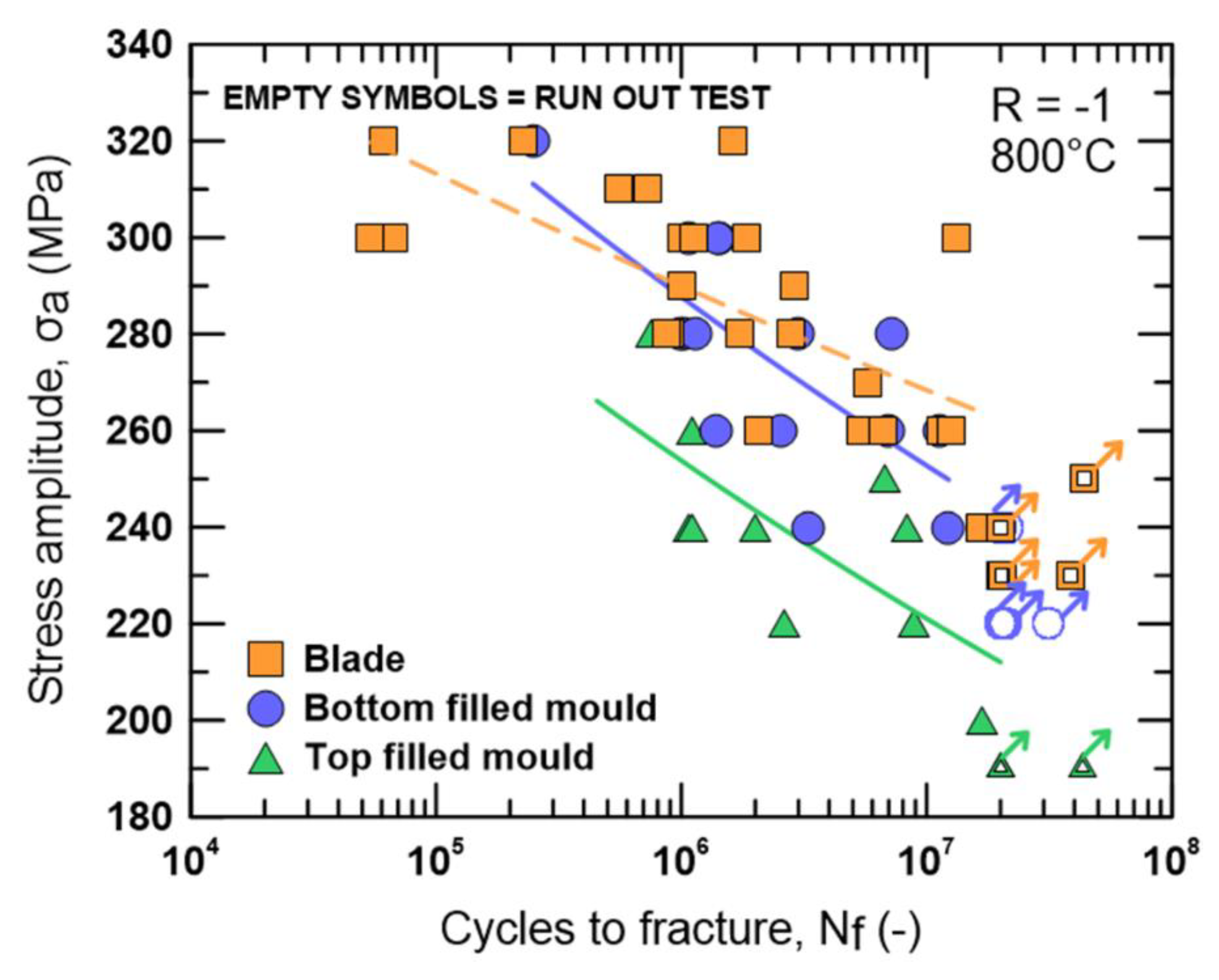
Figure 12 depicts the concluding comparison of the fatigue data acquired by testing of specimens produced by both mould filling setups and the specimens extracted from the blade. Due to the comparable porosity level, the BF pattern specimens represent well the fatigue performance of the blade, supported by similar fatigue limit.
The fracture surfaces of all batches of specimens exhibited similar features. The vicinity of initiation sites frequently contains facets indicating crystallographic stage I mode of the fatigue crack growth. Facets are a direct consequence of intensive strain localization into favourably oriented slip planes, which are promoted by stress concentrators such as pores, shrinkages, carbides, and γ/γ′ eutectics. In cast alloys, it is generally accepted that shrinkages and pores are the most critical structural defects [42,46]; therefore, the position of a fatigue crack initiation site is closely related to a position of casting defect, as it was already shown in the previous study [6]. In the case of a defect-free structure, the fatigue crack initiation from the fracture surface is the most frequent. This fact correlates well with the porosity measurements of the fatigued specimens presented in Figure 8 and the fracture analysis, shown in Figure 9, Figure 10 and Figure 11 and S2. The turbine blade specimens or the BF specimens exhibited the negligible level of porosity resulting in the transition of the fatigue crack initiation on specimen surface where a contribution to the crack initiation stemming from hot corrosion can be expected. Contrary to this finding, TF specimens (with or without HIP) contain a considerable degree of casting defects especially in specimen interior which result in interior fatigue crack initiation and subsequent propagation. With further crack growth, the fracture surface becomes more rugged and a fatigue crack propagates via interdendritic areas containing a high amount of carbides and γ/γ′ eutectics, see Figure S3.
The results confirm the dominant effect of casting defects on fatigue life, whereas grain size and texture are of minor effect. The separate casting of specimens for fatigue tests, aiming to avoid complex full-scale testing of blades or tedious and time-demanding extraction of test specimens from a blade, can deliver representative fatigue data under the condition of a similar level of porosity. Such a method of the fatigue tests can provide rapid and representative fatigue data for the design and manufacturing of a blade.
5. Conclusions
The results of this study indicate that the HCF life of polycrystalline cast MAR-M 247 superalloys at 800 °C is closely related to the retained porosity after the casting process and the HIP treatment. This finding presents a possibility for representative HCF testing of turbine blades by a set of separately cast specimens using standard laboratory fatigue testing systems. It has been concluded, based on the tests of three different series of specimens with diverse microstructural characteristics, that the determining parameter is the porosity size. The grain size and texture show only a minor effect on the overall HCF endurance and contribute most to the fatigue life scatter.
Supplementary Materials
The following are available online at https://www.mdpi.com/2075-4701/10/11/1460/s1, Figure S1: Macrostructure of the alloy in selected sections of the blade labelled according to the scheme shown in Figure 2a, Figure S2: Fractographs of (a) TF specimens without HIP, (b) TF specimen with HIP and (c) BF specimen, Figure S3: Backscattered electron micrograph of the fracture surface showing the presence of carbides and gas pores, favourable sites for the fatigue crack propagation.
Author Contributions
Conceptualization, M.Š., V.H. and P.H.; methodology, validation, investigation, data curation and visualization, M.Š. and V.H.; formal analysis and writing—original draft preparation, M.Š.; resources and supervision, P.H. and L.K.; writing—review and editing, V.H., L.K. and P.H.; project administration, P.H. and V.H.; funding acquisition, P.H. and K.H. All authors have read and agreed to the published version of the manuscript.
Funding
This research was financially supported by the project CZ.01.1.02/0.0/0.0/15_019/0004399 of Ministry of Industry and Trade of the Czech Republic.
Acknowledgments
Authors also acknowledge the equipment base of research infrastructure IPMinfra (LM2015069) and CEITEC (LQ1601) used during the research activities.
Conflicts of Interest
The authors declare no conflict of interest.
References
- Lin, H.; Geng, H.P.; Zhang, Y.Y.; Li, H.; Liu, X.Y.; Zhou, X.F.; Yu, L. Fatigue Strength and Life Prediction of a MAR-M247 Nickel-Base Superalloy Gas Turbine Blade with Multiple Carbide Inclusions. Strength Mater. 2019, 51, 102–112. [Google Scholar] [CrossRef]
- Liu, G.; Salvat Cantó, J.; Winwood, S.; Rhodes, K.; Birosca, S. The effects of microstructure and microtexture generated during solidification on deformation micromechanism in IN713C nickel-based superalloy. Acta Mater. 2018, 148, 391–406. [Google Scholar] [CrossRef] [Green Version]
- Liu, Y.; Kang, M.; Wu, Y.; Wang, M.; Li, M.; Yu, J.; Gao, H.; Wang, J. Crack formation and microstructure-sensitive propagation in low cycle fatigue of a polycrystalline nickel-based superalloy with different heat treatments. Int. J. Fatigue 2018, 108, 79–89. [Google Scholar] [CrossRef]
- Lamm, M.; Singer, R.F. The Effect of Casting Conditions on the High-Cycle Fatigue Properties of the Single-Crystal Nickel-Base Superalloy PWA 1483. Metall. Mater. Trans. A 2007, 38, 1177–1183. [Google Scholar] [CrossRef]
- Kunz, L.; Lukáš, P.; Konečná, R.; Fintová, S. Casting defects and high temperature fatigue life of IN 713LC superalloy. Int. J. Fatigue 2012, 41, 47–51. [Google Scholar] [CrossRef]
- Smid, M.; Hornik, V.; Hutar, P.; Hrbacek, K.; Kunz, L. High Cycle Fatigue Damage Mechanisms of MAR-M 247 Superalloy at High Temperatures. Trans. Indian Inst. Met. 2016, 69, 393–397. [Google Scholar] [CrossRef]
- He, L.Z.; Zheng, Q.; Sun, X.F.; Guan, H.R.; Hu, Z.Q.; Tieu, A.K.; Lu, C.; Zhu, H.T. Effect of carbides on the creep properties of a Ni-base superalloy M963. Mater. Sci. Eng. A 2005, 397, 297–304. [Google Scholar] [CrossRef]
- Liu, L.R.; Jin, T.; Zhao, N.R.; Wang, Z.H.; Sun, X.F.; Guan, H.R.; Hu, Z.Q. Effect of carbon addition on the creep properties in a Ni-based single crystal superalloy. Mater. Sci. Eng. A 2004, 385, 105–112. [Google Scholar] [CrossRef]
- Ruttert, B.; Meid, C.; Mujica Roncery, L.; Lopez-Galilea, I.; Bartsch, M.; Theisen, W. Effect of porosity and eutectics on the high-temperature low-cycle fatigue performance of a nickel-base single-crystal superalloy. Scr. Mater. 2018, 155, 139–143. [Google Scholar] [CrossRef]
- Asquith, G.; Pickard, A.C. Fatigue testing of gas turbine components. High Temp. Technol. 1988, 6, 131–143. [Google Scholar] [CrossRef]
- Hu, D. Combined fatigue experiments on full scale turbine components. Aircr. Eng. Aerosp. Technol. 2013, 85, 4–9. [Google Scholar] [CrossRef]
- Kiyak, Y.; Fedelich, B.; May, T.; Pfennig, A. Simulation of crack growth under low cycle fatigue at high temperature in a single crystal superalloy. Eng. Fract. Mech. 2008, 75, 2418–2443. [Google Scholar] [CrossRef]
- Witek, L. Simulation of crack growth in the compressor blade subjected to resonant vibration using hybrid method. Eng. Fail. Anal. 2015, 49, 57–66. [Google Scholar] [CrossRef]
- Chen, L.; Liu, Y.; Xie, L. Power-exponent function model for low-cycle fatigue life prediction and its applications – Part II: Life prediction of turbine blades under creep–fatigue interaction. Int. J. Fatigue 2007, 29, 10–19. [Google Scholar] [CrossRef]
- Lin, B.; Zhao, L.G.; Tong, J.; Christ, H.J. Crystal plasticity modeling of cyclic deformation for a polycrystalline nickel-based superalloy at high temperature. Mater. Sci. Eng. A 2010, 527, 3581–3587. [Google Scholar] [CrossRef] [Green Version]
- Xue, X.; Xu, L. Numerical simulation and prediction of solidification structure and mechanical property of a superalloy turbine blade. Mater. Sci. Eng. A 2009, 499, 69–73. [Google Scholar] [CrossRef]
- Whitesell, H.S.; Li, L.; Overfelt, R.A. Influence of solidification variables on the dendrite arm spacings of Ni-based superalloys. Metall. Mater. Trans. B 2000, 31, 546–551. [Google Scholar] [CrossRef]
- El-Bagoury, N.; Nofal, A. Microstructure of an experimental Ni base superalloy under various casting conditions. Mater. Sci. Eng. A 2010, 527, 7793–7800. [Google Scholar] [CrossRef]
- Holländer, D.; Kulawinski, D.; Weidner, A.; Thiele, M.; Biermann, H.; Gampe, U. Small-scale specimen testing for fatigue life assessment of service-exposed industrial gas turbine blades. Int. J. Fatigue 2016, 92, 262–271. [Google Scholar] [CrossRef]
- Yan, X.J.; Qi, M.J.; Deng, Y.; Chen, X.; Sun, R.J.; Lin, L.S.; Nie, J.X. Investigation on Material’s Fatigue Property Variation Among Different Regions of Directional Solidification Turbine Blades-Part II: Fatigue Tests on Bladelike Specimens. J. Eng. Gas Turbines Power-Trans. ASME 2014, 136, 102503. [Google Scholar] [CrossRef]
- Harris, K.; Erickson, G.L.; Schwer, R.E. MAR M 247 derivations—CM 247 LC DS alloy, CMSX® single crystal alloys, properties and performance. In Proceedings of the 1984, Seven Springs Mountain Resort, Champion, PA, USA, 2 October 1984. [Google Scholar]
- Janowski, G.M. The Effect of Tantalum on the Structure/Properties of Two Polycrystalline Nickel-Base Superalloys: B-1900+ Hf MAR-M247. Master’s Thesis, Michigan Technological University, Houghton, MI, USA, 1985. [Google Scholar]
- Kurz, W.; Fisher, D.J. Fundamentals of Solidification, 4th ed.; Trans Tech Publications: Aedermannsdorf, Switzerland, 1998. [Google Scholar]
- Mujica Roncery, L.; Lopez-Galilea, I.; Ruttert, B.; Huth, S.; Theisen, W. Influence of temperature, pressure, and cooling rate during hot isostatic pressing on the microstructure of an SX Ni-base superalloy. Mater. Des. 2016, 97, 544–552. [Google Scholar] [CrossRef]
- Haocheng, Z.; Anqiang, W.; Zhixun, W.; Zhufeng, Y.; Chengjiang, Z. Effects of Hot Isostatic Pressing (HIP) on Microstructure and Mechanical Properties of K403 Nickel-Based Superalloy. High Temp. Mater. Process. 2016, 35, 463–471. [Google Scholar] [CrossRef]
- Suresh, S. Fatigue of Materials, 2 ed.; Cambridge University Press: Cambridge, UK, 1998. [Google Scholar]
- Kunz, L.; Lukáš, P.; Konečná, R. High-cycle fatigue of Ni-base superalloy Inconel 713LC. Int. J. Fatigue 2010, 32, 908–913. [Google Scholar] [CrossRef]
- Yan, X.J.; Chen, X.; Sun, R.J.; Deng, Y.; Lin, L.S.; Nie, J.X. Investigation on Material’s Fatigue Property Variation Among Different Regions of Directional Solidification Turbine Blades-Part I: Fatigue Tests on Full Scale Blades. J. Eng. Gas Turbines Power-Trans. ASME 2014, 136, 102502. [Google Scholar] [CrossRef]
- Miao, J.; Pollock, T.M.; Wayne Jones, J. Crystallographic fatigue crack initiation in nickel-based superalloy René 88DT at elevated temperature. Acta Mater. 2009, 57, 5964–5974. [Google Scholar] [CrossRef]
- Šulák, I.; Obrtlík, K. AFM, SEM AND TEM study of damage mechanisms in cyclically strained mar-M247 at room temperature and high temperatures. Theor. Appl. Fract. Mech. 2020, 108, 102606. [Google Scholar] [CrossRef]
- Jiang, R.; Bull, D.J.; Evangelou, A.; Harte, A.; Pierron, F.; Sinclair, I.; Preuss, M.; Hu, X.T.; Reed, P.A.S. Strain accumulation and fatigue crack initiation at pores and carbides in a SX superalloy at room temperature. Int. J. Fatigue 2018, 114, 22–33. [Google Scholar] [CrossRef] [Green Version]
- Du, B.; Yang, J.; Cui, C.; Sun, X. Effects of grain size on the high-cycle fatigue behavior of IN792 superalloy. Mater. Design (1980-2015) 2015, 65, 57–64. [Google Scholar] [CrossRef]
- Gao, Y.; Stölken, J.S.; Kumar, M.; Ritchie, R.O. High-cycle fatigue of nickel-base superalloy René 104 (ME3): Interaction of microstructurally small cracks with grain boundaries of known character. Acta Mater. 2007, 55, 3155–3167. [Google Scholar] [CrossRef]
- Liu, G.; Winwood, S.; Rhodes, K.; Birosca, S. The effects of grain size, dendritic structure and crystallographic orientation on fatigue crack propagation in IN713C nickel-based superalloy. Int. J. Plast. 2020, 125, 150–168. [Google Scholar] [CrossRef]
- Leverant, G.R.; Gell, M. The influence of temperature and cyclic frequency on the fatigue fracture of cube oriented nickel-base superalloy single crystals. Metall. Trans. A 1975, 6, 367. [Google Scholar] [CrossRef]
- Bowles, C.Q.; Broek, D. On the formation of fatigue striations. Int. J. Fract. Mech. 1972, 8, 75–85. [Google Scholar] [CrossRef]
- Gunasegaram, D.R.; Farnsworth, D.J.; Nguyen, T.T. Identification of critical factors affecting shrinkage porosity in permanent mold casting using numerical simulations based on design of experiments. J. Mater. Process. Technol. 2009, 209, 1209–1219. [Google Scholar] [CrossRef]
- Flemings, M.C. Solidification processing. Metall. Trans. 1974, 5, 2121–2134. [Google Scholar] [CrossRef]
- Cox, M.; Wickins, M.; Kuang, J.P.; Harding, R.A.; Campbell, J. Effect of top and bottom filling on reliability of investment castings in Al, Fe, and Ni based alloys. Mater. Sci. Technol. 2000, 16, 1445–1452. [Google Scholar] [CrossRef]
- Wu, S.-P.; Li, C.-Y.; Guo, J.-J.; Su, Y.-Q.; Lei, X.-Q.; Fu, H.-Z. Numerical simulation and experimental investigation of two filling methods in vertical centrifugal casting. Trans. Nonferrous Met. Soc. China 2006, 16, 1035–1040. [Google Scholar] [CrossRef]
- Murakami, Y. Material defects as the basis of fatigue design. Int. J. Fatigue 2012, 41, 2–10. [Google Scholar] [CrossRef]
- Tammas-Williams, S.; Withers, P.J.; Todd, I.; Prangnell, P.B. The Influence of Porosity on Fatigue Crack Initiation in Additively Manufactured Titanium Components. Sci. Rep. 2017, 7, 7308. [Google Scholar] [CrossRef]
- Yi, J.Z.; Gao, Y.X.; Lee, P.D.; Flower, H.M.; Lindley, T.C. Scatter in fatigue life due to effects of porosity in cast A356-T6 aluminum-silicon alloys. Metall. Mater. Trans. A 2003, 34, 1879. [Google Scholar] [CrossRef]
- Wang, Q.G.; Apelian, D.; Lados, D.A. Fatigue behavior of A356-T6 aluminum cast alloys. Part I. Effect of casting defects. J. Light Met. 2001, 1, 73–84. [Google Scholar] [CrossRef]
- Horstemeyer, M.F.; Yang, N.; Gall, K.; McDowell, D.; Fan, J.; Gullett, P. High cycle fatigue mechanisms in a cast AM60B magnesium alloy. Fatigue Fract. Eng. Mater. Struct. 2002, 25, 1045–1056. [Google Scholar] [CrossRef]
- Nicoletto, G.; Konečná, R.; Fintova, S. Characterization of microshrinkage casting defects of Al–Si alloys by X-ray computed tomography and metallography. Int. J. Fatigue 2012, 41, 39–46. [Google Scholar] [CrossRef]
Figure 1.
Schemes of the utilized casting setups: (a) real blade cast by the top filling system, (b) the mould with the top radial filling system, and (c) the pattern with the bottom radial filling system. The melt flow during pouring is depicted by arrows.
Figure 1.
Schemes of the utilized casting setups: (a) real blade cast by the top filling system, (b) the mould with the top radial filling system, and (c) the pattern with the bottom radial filling system. The melt flow during pouring is depicted by arrows.

Figure 2.
Schemes of (a) the blade cutting plan with indicated positions of extracted fatigue specimens (highlighted as red circles) and metallographic sample sections; (b) the specimen geometry.
Figure 2.
Schemes of (a) the blade cutting plan with indicated positions of extracted fatigue specimens (highlighted as red circles) and metallographic sample sections; (b) the specimen geometry.

Figure 3.
Microstructure of MAR-M 247 superalloy.

Figure 4.
Structure of the specimen gauge sections extracted from three different positions of a gas turbine blade.
Figure 4.
Structure of the specimen gauge sections extracted from three different positions of a gas turbine blade.

Figure 5.
Dendritic structures of the specimen gauge sections.

Figure 6.
(001) pole of longitudinal specimen gauge sections obtained by three different casting conditions depict random crystallographic orientation. High intensities are caused by coarse grains.
Figure 6.
(001) pole of longitudinal specimen gauge sections obtained by three different casting conditions depict random crystallographic orientation. High intensities are caused by coarse grains.

Figure 7.
Stress-life (S-N) diagram for individual blade positions cycled at 800 °C.

Figure 8.
S-N diagram of particular batches of pre-cast specimens cycled at 800 °C. The numbers of each data point represent the Feret diameter of a casting defect (in µm) responsible for the fatigue crack initiation.
Figure 8.
S-N diagram of particular batches of pre-cast specimens cycled at 800 °C. The numbers of each data point represent the Feret diameter of a casting defect (in µm) responsible for the fatigue crack initiation.

Figure 9.
Fracture surface of top filling (TF) hot isostatic pressing (HIP)ed specimen (σa = 280 MPa, Nf = 0.752 × 10⁶ cycles) (a). Fatigue crack initiated from large complex shrinkage situated in gauge length interior (b). The blue dashed line highlights the “fish-eye” representing the fatigue crack propagation period prior to reaching a specimen surface. The white dashed line refers to the final stage of crack propagation before final failure. The yellow line represents the plane of longitudinal section for electron backscatter diffraction (EBSD) analysis underneath the surface (c).

Figure 10.
Fracture surface of bottom filling (BF) specimen (σa = 300 MPa, Nf = 1.438 × 10⁶ cycles) (a). Fatigue crack initiated from small shrinkage (b). The blue dashed line highlights the fish-eye area representing fatigue crack propagation prior to reaching specimen surface. The white dashed line depicts the final stage of the crack propagation before final failure. The yellow line represents the plane of longitudinal section for EBSD analysis underneath the surface (c).

Figure 11.
Fracture surface of blade shank specimen (σa = 300 MPa, Nf = 106 cycles) with surface crack initiation highlighted by a red rectangle (a). The white dashed line highlights final stage of the crack propagation before final failure. Detail of the crack initiation site is depicted in (b). The yellow line represents the plane of longitudinal section for EBSD analysis underneath the surface (c).

Figure 12.
Comparison of high cycle fatigue (HCF) performance of the blade and the specimens cast by two different mould filling setups.
Figure 12.
Comparison of high cycle fatigue (HCF) performance of the blade and the specimens cast by two different mould filling setups.


Table 1.
Chemical composition of MAR–M 247 superalloy (in wt. %).
| C | Cr | W | Co | Al | Ti | Ta | Hf | Mo | Nb | B | Ni |
|---|---|---|---|---|---|---|---|---|---|---|---|
| 0.15 | 8.37 | 9.92 | 9.91 | 5.42 | 1.01 | 3.05 | 1.37 | 0.67 | 0.04 | 0.015 | bal. |
Table 2.
Basic microstructural parameters.
| Average Grain Area [mm2] | Grain Size Scatter [mm2] | SDAS [µm] | |
|---|---|---|---|
| Root | 4.91 | 0.1–51.21 | 136 ± 39 |
| Shank | 4.35 | 0.02–30.62 | 105 ± 24 |
| Airfoil | 1.46 | 0.01–19.36 | 101 ± 27 |
| Top filled mould without HIP * | 0.33 | 0.01–5.76 | 33 ± 5 |
| Top filled mould with HIP | 0.36 | 0.02–6.14 | 34 ± 8 |
| Bottom filled mould | 2.45 | 0.02–18.66 | 39 ± 8 |
* Hot isostatic pressing (HIP).
Publisher’s Note: MDPI stays neutral with regard to jurisdictional claims in published maps and institutional affiliations. |
© 2020 by the authors. Licensee MDPI, Basel, Switzerland. This article is an open access article distributed under the terms and conditions of the Creative Commons Attribution (CC BY) license (http://creativecommons.org/licenses/by/4.0/).
Share and Cite
MDPI and ACS Style
Šmíd, M.; Horník, V.; Kunz, L.; Hrbáček, K.; Hutař, P. High Cycle Fatigue Data Transferability of MAR-M 247 Superalloy from Separately Cast Specimens to Real Gas Turbine Blade. Metals 2020, 10, 1460. https://doi.org/10.3390/met10111460
AMA Style
Šmíd M, Horník V, Kunz L, Hrbáček K, Hutař P. High Cycle Fatigue Data Transferability of MAR-M 247 Superalloy from Separately Cast Specimens to Real Gas Turbine Blade. Metals. 2020; 10(11):1460. https://doi.org/10.3390/met10111460
Chicago/Turabian StyleŠmíd, Miroslav, Vít Horník, Ludvík Kunz, Karel Hrbáček, and Pavel Hutař. 2020. "High Cycle Fatigue Data Transferability of MAR-M 247 Superalloy from Separately Cast Specimens to Real Gas Turbine Blade" Metals 10, no. 11: 1460. https://doi.org/10.3390/met10111460
Note that from the first issue of 2016, this journal uses article numbers instead of page numbers. See further details here.