1. Introduction
As it is commonly known in the EU, Natura 2000 is a network of nature protection areas in EU states. Nowadays, there are 27,312 such sites across Europe, with terrestrial area covering almost 18% percent of the land of EU countries [
1]. They vary significantly in their character. There are agricultural and forested localities, and many of them are connected to wetlands, water streams, and water reservoirs, or they are located in the relative wilderness of National Parks and large Nature Protected Territories. However, we may find them quite easily also in urban areas. Unfortunately, Natura 2000 sites, regardless of their individual locations, may suffer as any “ordinary” area from various types of environmental pollution [
2]. Old deposits of toxic metals of anthropogenic origin (mining, metallurgy, chemical industry, treatment of metallic ores, etc.) represent a specific problem that often requires to be approached technologically in order to fulfil Natura 2000 protection standards [
3,
4]. It is obvious that the chosen decontamination approach must be non-invasive to the environment, but still as highly effective as is usual when treating, for example, brownfields. However, utilization of decontamination tools intended for brownfields is, in most cases, inacceptable. Due to industrial activities on many sites, hexavalent chromium, which originates from the galvanic processing of metals, is often present.
Most of the conventional methods for hexavalent chromium removal were, one after another, excluded from the list of potential decontamination tools. These were tested in preliminary experiments, and then, critically assessed. Cr
6+ reduction in an acid environment (optimal pH = 4.5 to 5) using Na
2SO
3 yielding Cr
3+ and its precipitation using NaOH or Ca(OH)
2 towards Cr(OH)
3 at pH = 9 requires ex situ operation, but the main disqualification mark is the extensive use of potentially risky chemicals [
5]. The addition of a precipitating agent (FeCl
3, Fe
2SO
4, or Al
2(SO
4)
3) to the effluent stream forms, at suitable conditions (e.g., pH), insoluble aggregates that bind to the contaminants and form a sludge that can be physically separated from the aqueous phase (e.g., by settlement, flotation, filtration) [
6]. Cr
6+ reduction using nano-sized Fe can be applied in situ but nano-sized Fe requires a special filtration system, is expensive, and very often has low effectiveness [
7]. Ionic exchange applied for the additional treatment of residual Cr
6+ concentrations or adsorption on active carbon reveals the main disadvantage in the requirement of regeneration of ion exchangers and activated carbon or their storage. Under the conditions of the treated locality, the method would be the most expensive per 1 m
3 of treated water [
8,
9]. There are also other methods of Cr
6+ adsorption—the use of an adsorbent improved with magnetic particles, enabling enhancement of adsorbing efficiency and utilization of persistent free radicals for the reduction of Cr
6+. All these approaches are still at the experimental level and their practical utilization is rather questionable [
10]. Microbial methods are not effective due to the high toxicity of Cr
6+ [
11].
Based on our previous knowledge, we finally chose to design, develop, optimize, and process modular electrocoagulation for the reduction of Cr
6+ to Cr
3+ and its subsequent removal (as sludge with Cr
3+). It should be briefly reminded that electrocoagulation (EC) is an alternative to standard chemical coagulation (CC) [
12,
13]. It allows the water treatment to be carried out with no or significantly reduced amounts of coagulant chemicals that can potentially exhibit health and safety risks during transportation, handling, process use, or storage. It also offers the potential for reduced sludge volumes or much higher removal efficacy [
14,
15]. Unlike CC, electrocoagulation does not require the addition of any external coagulating agent as it is formed in situ under optimized process conditions. The process can be supported by the addition of Ca(OH)
2 as it is beneficial for low concentrations of Ni
2+ in treated effluent [
16]. It does not serve for precipitation of Cr(OH)
3 as this is ensured during the electrocoagulation step.
The fundamental physical mechanism of EC performance is colloid destabilization. This results in contaminant removal from solution (by precipitation) and occurs through charge balancing of colloidal particles, leading to particle aggregation and precipitation [
17]. The principal difference between CC and EC is the mechanism of the addition of ions to the treated solution. Whilst in CC this is carried out via the addition of coagulant chemicals (e.g., FeCl
3 or Al
2(SO
4)
3), in EC, metal ions dosing is achieved through the electrodissolution of an electrode (e.g., steel or aluminum). Mechanisms of electrocoagulation and ongoing electrochemical reactions can be found elsewhere [
12,
18,
19].
The main intention of this communication is to report on the strategy of decontamination of a nature reserve area from chromium and nickel, by using an advanced modular electrocoagulation method. The technology is environment-friendly and does not bring any additional risks to the valuable area. It is highly effective and capable to “fulfil the task” of decontamination of the locality in a reasonable time and for a competitive cost.
2. The Locality and the EC Process
2.1. Site History
Zlate hory (Golden Mountains) is a typical example of a small town located in Zlaty potok (Golden Creek) in the countryside below the ridge of the eastern part of Jeseniky Mountains (Czech–Polish Odra river border). The town was recognized for river gold-bringing sands already in the medieval ages. Gold sources were exhausted quickly, but surveyors and prospectors searching for metallic ores, especially those involving iron, nickel, lead, copper, and chromium, started to come soon afterwards. The industrial revolution induced the expansion of small engineering, metallurgy, chemistry, machinery, and other companies, bringing not only enormous prosperity to the originally remote mountain region, but also, as would be clearly revealed years later, a heavily polluted environment.
To find some gold in Zlaty potok (Golden Creek) is very rare now. On the other hand, the occurrences of European otter (Lutra lutra), Wild cat (Felis silvestris), Eurasian lynx (Lynx lynx), Bullhead small fish (Cottus gobio), Black stork birds (Ciconia nigra), and European hoopoe (Upupa epops) are all exquisite indicators of the nature value of this locality. Unfortunately, due to industrial activities spanning from the 1860s to the 1980s, there is also a high occurrence of hexavalent chromium (Cr6+) deposits.
2.2. Contamination
The contaminated area is located in a zone of a company working in the metallurgic industry and dealing also with galvanic plating. The contaminated water contains mainly Cr6+ and Ni2+ ions as a consequence of old industrial pollution. The area is equipped with a series of boreholes, enabling monitoring of the contamination concentration.
The depth of the boreholes is 6 m and the level of underground water level oscillates between 3 and 5 m (affected by the intensity of draining the borehole and climatic conditions). The contaminated water in the borehole had been monitored long before the campaign started. The long-term average pH value oscillates between 3.1 and 4.9, with conductivity oscillating between 3 to 5 mS/cm (temperature 15–19 °C). The characteristic contents of contaminants, pH, and conductivity are given in
Table 1.
It is obvious that the highest concentration in groundwater reveals Ni2+, which is higher than 90 mg/L. The second dominating contaminant is chromium at a concentration 43 mg/L, of which hexavalent chromium comprises 41.9 mg/L. Contamination by these metallic ions is a consequence of industrial activity on this site, which was already described above. Other contaminants are of minor importance. The polluted area was about 150 × 150 m (22,500 m2), and it contained approximately 78,750 m3 of water contaminated with Cr6+ and Ni2. The contaminant cloud was located in a subsurface water layer (3 to 6 m deep). Targeted concentrations after treatment were 0.1 mg/L for Cr6+, 0.5 mg/L for Crtot., and 0.8 for Ni2+.
2.3. Process Design
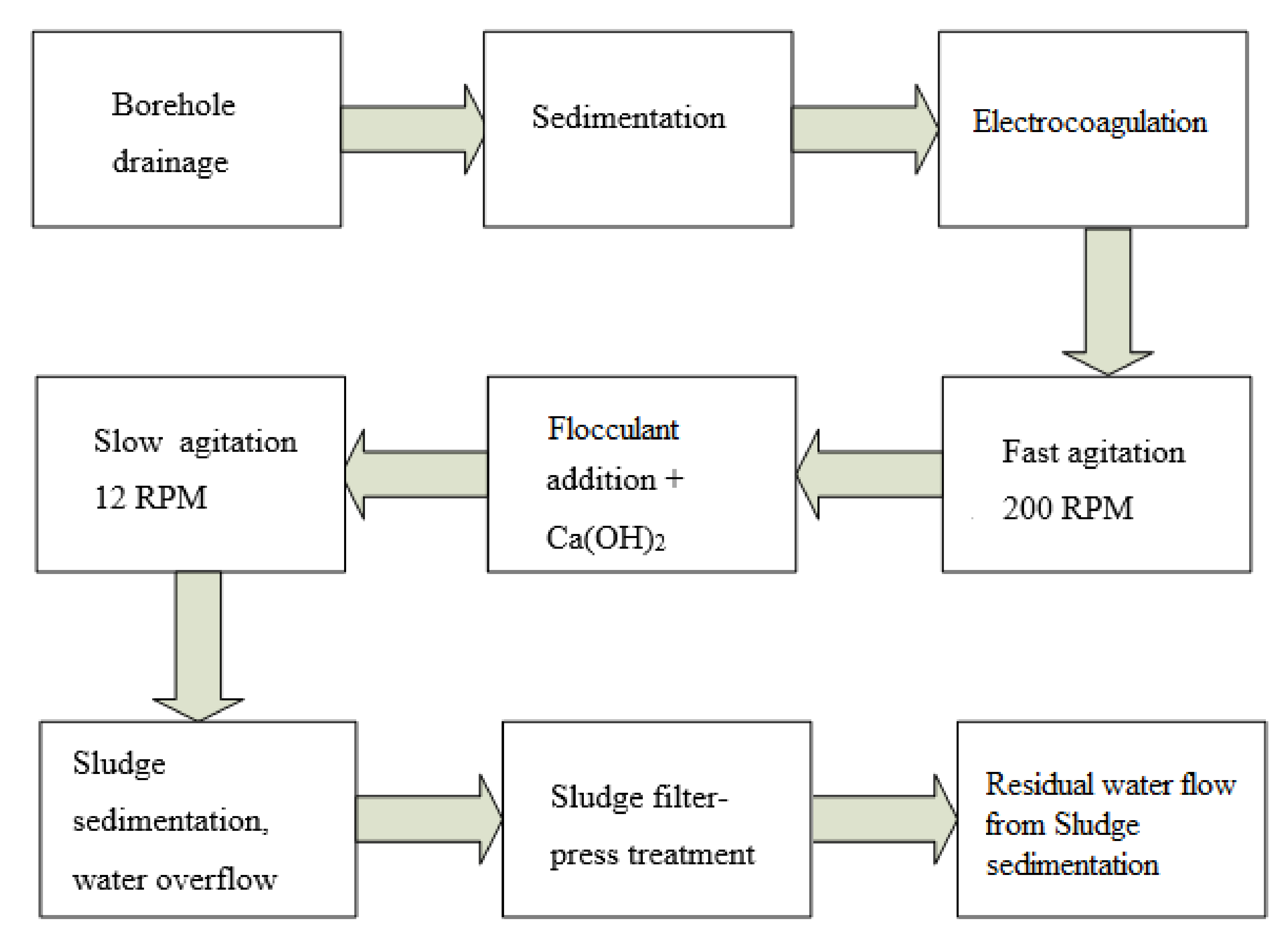
Figure 1 shows the stepwise procedure of the contaminated effluent treatment.
Firstly, the contaminated water is pumped from the borehole to a storage tank for separation of solid particles appearing together with the pumped water (stones, sand, clay).
After primary sedimentation, the water is pumped through an electrocoagulation (EC) cell where Fe2+ dosing takes place. The EC cell is constructed as a continuous apparatus with a single flow-through loop.
After Fe2+ dosing, rapid agitation with 200 rpm is applied in order to homogenize the treated water with dosed coagulant.
Flocculant (SUPERFLOC® A130, Kemira, Kemifloc, Prerov, Czech Republic) and Ca(OH)2 addition to the treated water is implied before the slow agitation period in order to support particle growth and their coalescence to larger aggregates (similar to standard industrial jar-testing).
The constructed unit is modular—this means that if a higher capacity of the process is required, more EC modules (containers) can be connected in series.
Ca(OH)
2 was mainly added to EC-treated effluent in order to enhance the removal of Ni
2+ ions. EC itself was unable to remove them below the desired limit (0.8 mg/L) because the pH increase during dosing was not sufficiently high for complete removal of Ni. Gentle addition of Ca(OH)
2 brought the desired result in efficiency. The course of Ni residual concentrations followed the course of Fe residual concentrations. In addition, Ca(OH)
2 could not be used separately for treatment of this industrial effluent because it was unable to remove Cr
6+ ions (see
Table 2).
Ca(OH)2 was capable of very efficient removal of Ni2+ and other metals, but it was not able to remove Cr6+. Treated water then enters the sedimentation tank to separate the precipitated coagulant. Treated water leaves the tank through the overflow and the coagulated sludge is treated with a filter-press (Antares AKHR 400/25-00, ANTARES-AZV s.r.o., Prerov–Dlouhonice, Czech Republic).
2.4. EC Cell Characteristics
The electrodes are constructed as metallic sheets made of mild steel with dimensions 750 × 75 × 5 mm. The gap between the electrodes is set at 6 mm and the complete electrode pack consists of 4 anodes and 4 cathodes, providing 7 channels between the electrodes with 6 mm width. The highest safe current input was determined at 90 A; above this value, an undesired rapid overheating of the conductive wires was observed. The electrodes are connected to a power supply (EA PSI 8080 120 2U), enabling set up of the current in the range 0–120 A, with 0–80 V. The cell is also equipped with a polarity switch.
Switching between the anode and the cathode is possible because they are of identical material (mild steel). While the anode is being consumed, the cathode remains unconsumed. Their switching in defined periods of time enables prolongation of the electrode pack lifetime. Technical data of the EC cell are given in the
Table 3.
Total and residual concentrations of Cr, Ni2+ were determined by microwave plasma-atomic emission spectrometry (Agilent 420 MP-AES, Agilent Technologies, Santa Clara, CA, USA). Cr6+ was determined by UV–vis spectrophotometry by reaction with diphenylcarbazide at 540 nm. Conductivity and pH were measured with a multi-parameter probe (WTW Multi 3620, WTW s.r.o., Prague, Czech Republic).
3. Results and Discussion
During the testing period, a range of typical technical problems that can be associated with pilot scale and the prototype unit occurred—unstable weather, clogging of pumps caused by inappropriate setup, oscillation of flow rate, etc. However, all problems were solved and the presented data contain results obtained by operation without interruption. The entire campaign lasted three individual workweeks and this section describes one of these uninterrupted weeks (all three weeks’ data are given in the
Supplementary Materials).
The EC cell was operated continuously at a flow rate of 350 L/h. The constant flow rate was ensured by an air-operated diaphragm pump and an assigned regulation valve. The flow rate was monitored on a conical flow meter. The unit contains two electrochemical cells. We decided to designate them as Cell A and Cell B. If Cell A is in use during experiment, Cell B is in stand-by mode and vice versa.
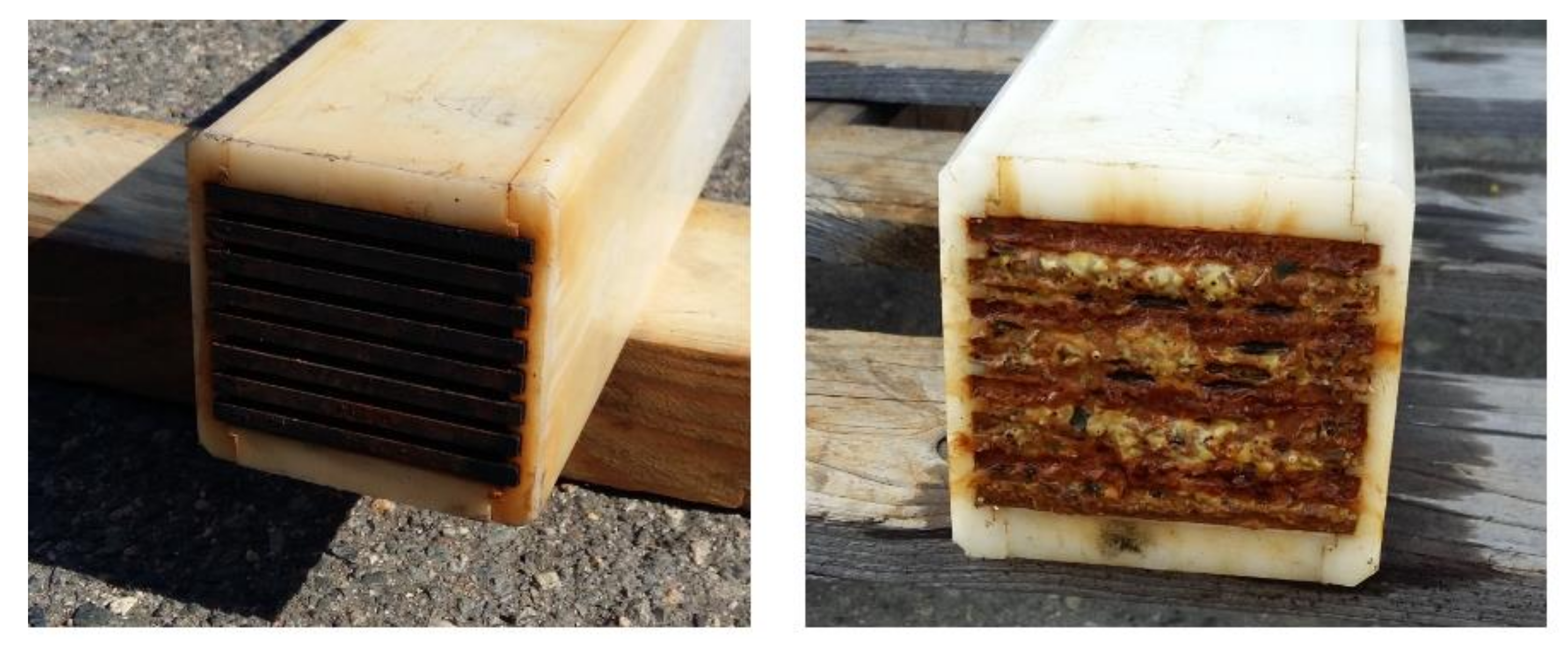
The left part of
Figure 2 displays the details of a fresh electrode pack ready for testing. The right part of
Figure 2 shows the passivated surface requiring maintenance. Passivation is caused by surface clogging due to the agglomeration of produced sludge and coagulation of contaminants and salts contained in groundwater. In addition, some non-clarified mechanisms can contribute to the passivation phenomena. This undesired clogging of electrode surface caused a conductive connection between the anode and cathode, instigating a closed circuit and consequently, electric discharge. This is accompanied with the rise in electric resistance. This passivated surface required mechanical cleaning and chemical regeneration using 5% H
3PO
4.
Some of the process parameters had to be optimized prior to pilot scale testing in order to resolve all possible troubleshooting. These included: flow rate and current input—dosing of coagulant, mixing regime, dose of flocculant, and addition of Ca(OH)
2. Flow rate and current input are crucial parameters closely bound together and they are the main indicators of the process’ performance. Mixing regime and dose of coagulant are important for the separation of coagulated particles from the treated solution. Ca(OH)
2 addition was applied to enhance removal of Ni
2+ by an increase in pH. All process parameters were optimized as published before [
16].
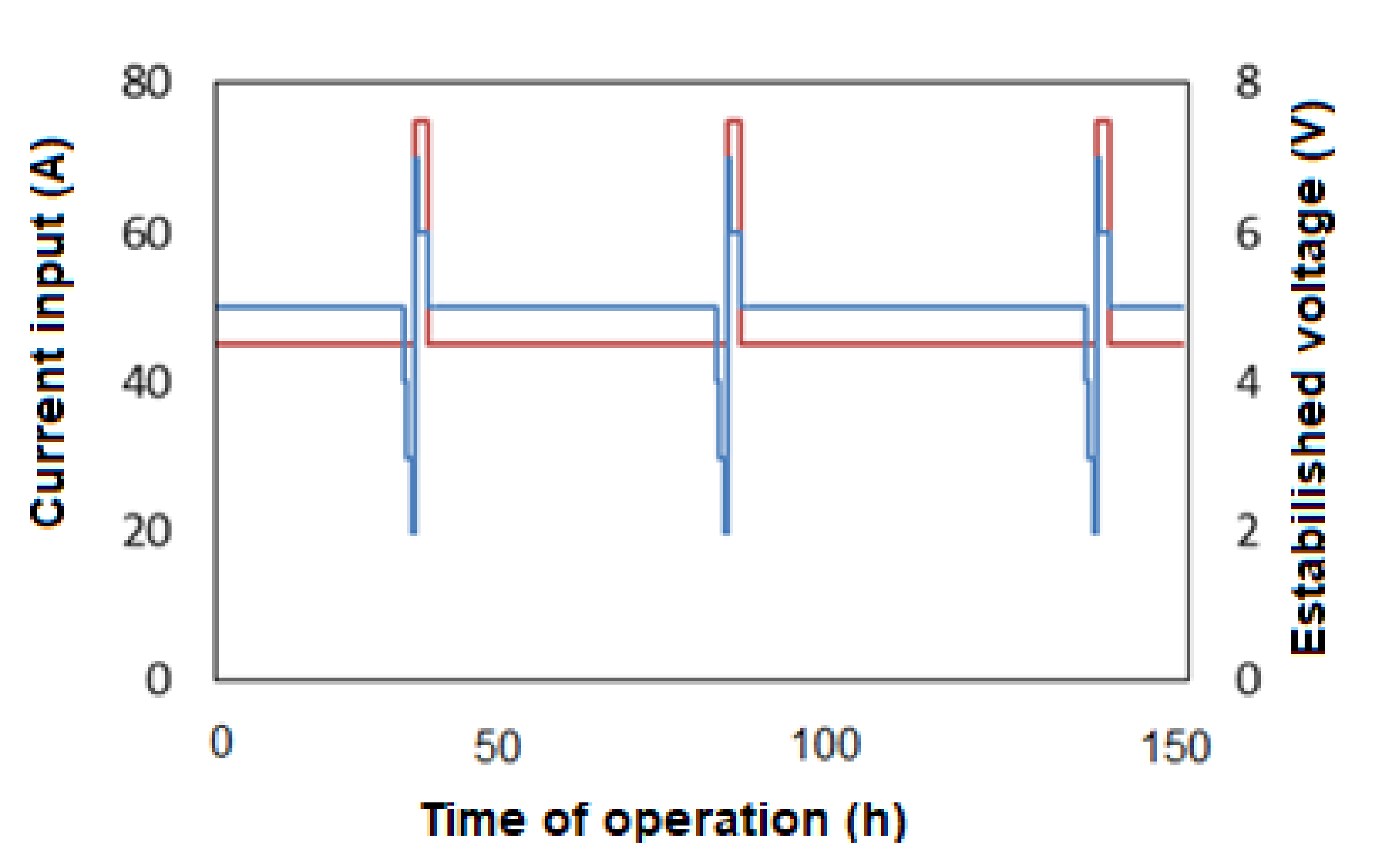
Current input was kept during the testing period at a constant value of 45 A and its value was set based on previous optimization experiments that provided stable performance in the removal of selected contaminants. Its course is represented by a red line in
Figure 3. After 35 h, there was a peak of current input at 75 A and this represented the need of electrode pack maintenance due to the clogging of the electrode surface and consequently, caused the presence of short circuit areas. This is accompanied by a drop and immediate rise in established voltage at the same time. It is obvious that the established voltage is nearly stable and any eye-catching deviation may indicate a process problem. The phenomena were periodically repeated within an interval of 35–50 h, showing that at the current technical arrangement, operation of the EC cell without maintenance is possible approx. two days. Switching between EC cells did not require termination of operation.
3.1. Main Contaminants Removal
The concentrations of Cr
6+ and Ni
2+ were noted to be decreasing during the experimental campaign and the decrease varied between 15% and 25% of day 0’s concentration (91.6 mg/L for Ni
2+ and 43 mg/L for Cr). This could have been caused by the continuous pumping of water to the storage tank and subsequent natural dilution caused by underground inflow of water to the borehole. During the process, the reduction of Cr
6+ ions is performed according to the hypothesized equation:
This is followed by the formation of Cr(OH)
3 and Ni(OH)
2 and their co-precipitation and adsorption in the coagulant sludge according to conjectured reactions:
Long-term variation of input concentrations can be found in the supplementary data.
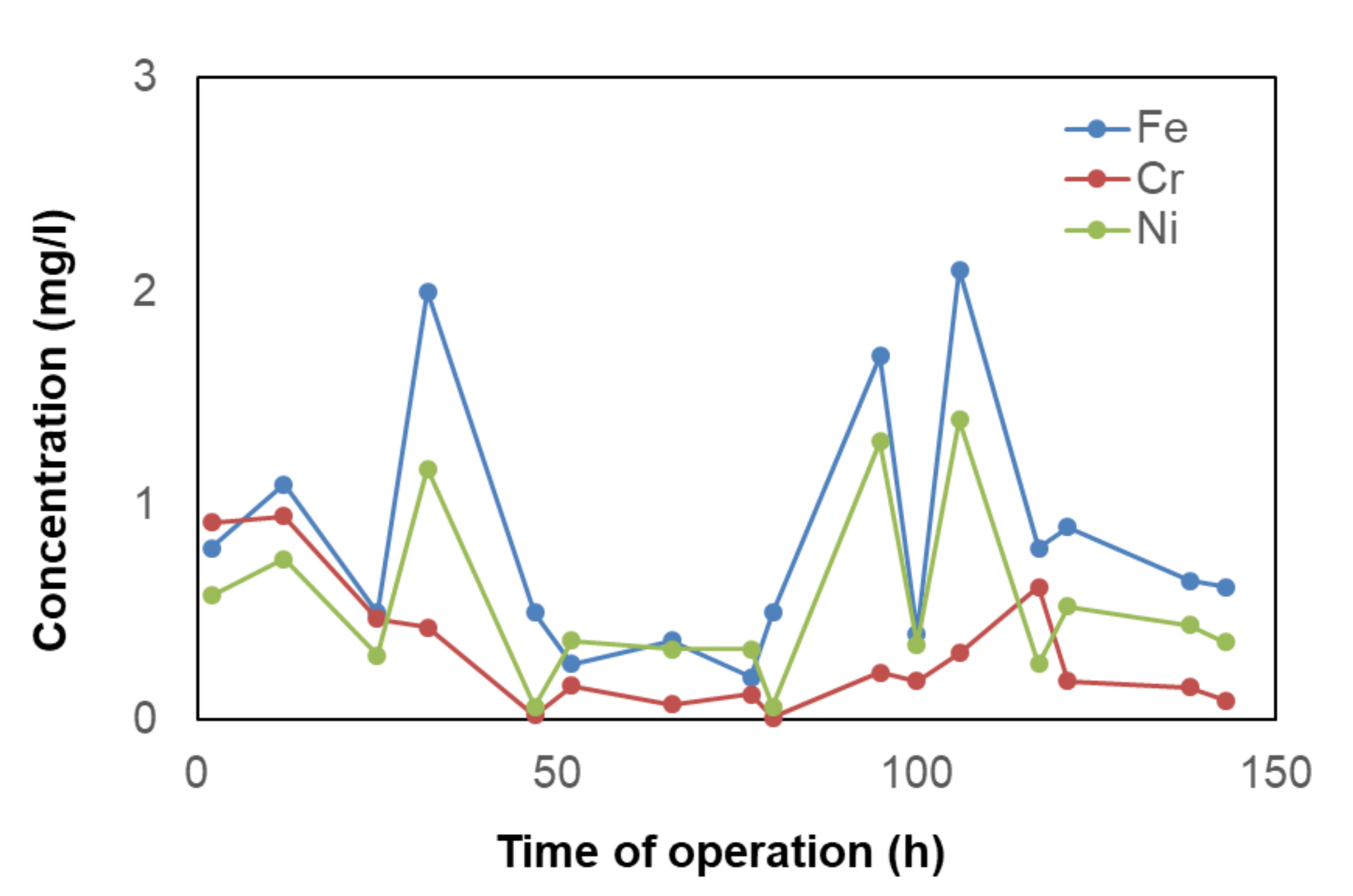
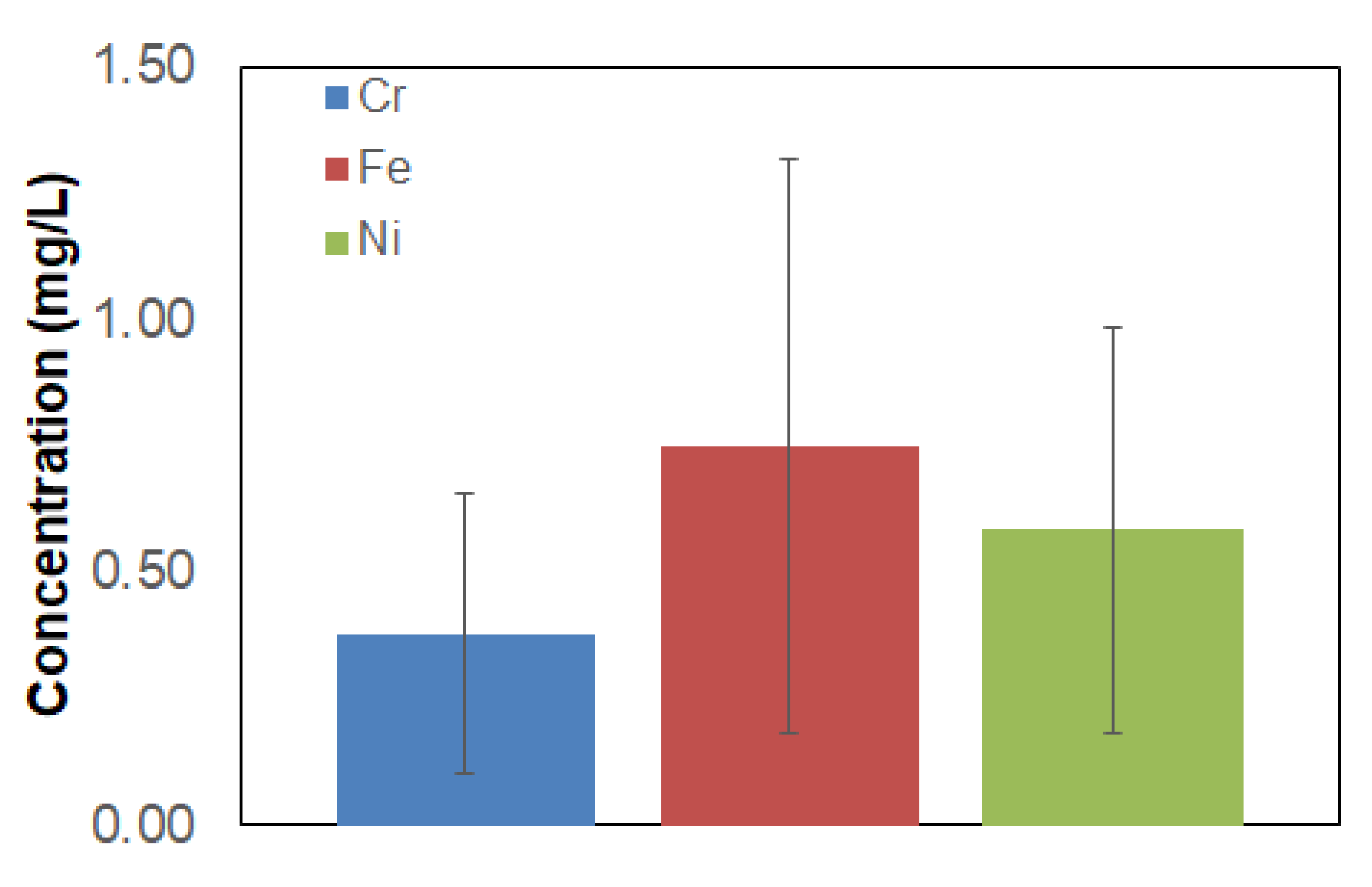
An example of residual concentrations of the main contaminants is depicted in
Figure 4. Full data of three weeks’ testing are included in the
Supplementary Materials (Figure S7). The residual concentration of Cr
tot. was kept below 0.5 mg/L, which was the limit for draining treated water back to the ground. Only at the beginning residual concentration was higher than the permissible limit, but this was caused by launching the technology into operation. From this, it is obvious that a carefully controlled well-timed system of regeneration ensures long-term stable operation. The residual concentration of Ni
2+ exceeded the limit for Ni
2+ (0.8 mg/L) a few times and it can be seen that it correlated with the residual concentration of Fe. This might have been caused by the temporary decrease in pH to a value of 8, causing higher Ni solubility. Precipitated Fe(OH)
3 forms the main part of the sludge. A higher residual concentration of Fe (and correspondingly, Ni) might have also been caused by oxygen bubbles, which were being formed during the electrocoagulation process. That might have kept small flocs of Fe sludge suspended in the bulk volume. Average concentrations, including all data with variations, are given in
Figure 5. The confidence intervals include all three weeks’ data. This displays that the required residual concentrations of Ni and Cr are possible to be reached; however, further optimization would be needed.
The decrease in pH may have several reasons. Water is pumped to the EC cell with an air-operated diaphragm pump, which is supported by a compressor. With this pump, it may be difficult to regulate flow rate precisely and sometimes, non-precise regulation could cause short-term increase or decrease in the flow rate. Simultaneously, the Ca(OH)2 dosing was not interconnected to the current value of flow rate and due to manual regulation of the flow rate, it may have caused a temporary excess or lack of Ca(OH)2, causing an increase in residual concentration—the modular unit was a prototype. It is possible to assume that in the case of series manufacture, the pumping of water to be treated and the dosing of Ca(OH)2 would be fully automated and this would be avoided. Finally, natural variation in the borehole water level and its pH could act its role during the process, which is, unfortunately, not possible to influence.
Sludge collected at the bottom of the sedimentation tank had to be treated by using a filter-press. The residual concentration of metals in the water leaving the filter-press is given in
Table 4. The filter-press was operated once per day and the volume of treated water with concentrated sludge varied from 1 to 1.5 m
3.
It can be seen that the first values of residual concentration significantly differ from other concentrations and the content of contaminants is much higher. This was caused by the fact that there was a concentrated sludge from the previously performed experiments with a not sufficiently high degree of removal in the filter-press. Backward leaching of metals to treated water was thus observed. This could also have been caused by leaching of the smallest-grained particles from sludge to the treated water, which could have been intensified by a rise in filtration pressure in the fully filled filter-press and consequently, lower flow rate through the filter-press. After clearing out the filtering chambers, all residual concentrations of monitored contaminants were below detection limits. It is obvious that detected concentrations in water leaving the filter-press were lower than water leaving electrocoagulation after sedimentation. This might be caused by imperfect separation by sedimentation as some of the flocs might have been carried away by emerging oxygen during electrocoagulation and helped them to remain in bulk volume, while the filter-press effectively separated them.
Table 5 summarizes concentrations of Ni and Cr in influent, effluent, and sludge dewatering, including removal efficiencies.
During the entire period of testing the unit (not just the period presented in this manuscript), more than 74 m
3 of contaminated water was treated and 220 kg of electrocoagulation sludge was produced with 47% of dry matter. Standard chemical coagulation would produce up to 50% more sludge than electrocoagulation [
20]. Collected sludge was mineralized in aqua regia (1 g of sludge in 10 mL of aqua regia) under microwave conditions and the leachate was then diluted to 100 mL. Samples were analyzed on MP-AES and the concentrations of metals were calculated fordry matter. It is obvious that most of the removed contaminants remained in the concentrated sludge (see
Table 6).
The collected sludge enabled simple manipulation and disposal. After sampling, it was stored in the metallic barrel and then, treated as a non-hazardous waste (category II; based on leaching examination test). The leaching test was performed according to Czech regulation 294/2005 legal code. The sludge could not have been categorized in group I because of the higher leaching of fluorides that was allowed (limit is 1 mg/L, leachate contained 1.28 mg/L). Fluorides are bound in the form of CaF2, with Ks = 2.69 × 10⁻¹¹; equilibria concentration of fluorides is then 3.5 mg/L, therefore electrocoagulation leachate would most probably always exceed the limits for being categorized in group I (inert waste). The full protocol of the leaching test can be found in the supplementary material.
3.2. Operating Cost
Based on long-term testing, an estimation of operating cost was performed. All the costs are related to 1 m
3 of treated water. It is obvious that electric energy is the dominating item in determining the cost of the technology. The energy supply to the EC cells represents only 14% of the total energy consumed. The rest of the energy was consumed by other components requiring electricity (centrifugal pumps, sensors, mixing motors, etc.). The energy consumption of other apparatuses is given in
Table 7. It is important to point out that a range of these Natura 2000 sites have available small hydro plants (SHP); thus, the cost of electricity might be favorably low.
The second highest item determining the operating cost is the fabrication of the electrode pack (cutting and connecting electrodes from a steel sheet and working for their exchange in the cells). Other process costs are of minor importance, as can be seen in
Table 8.
The total process cost for treatment of groundwater on the treated site contaminated mainly with Cr6+ and Ni2+ was determined at 1.97 EUR/m3. The operating cost is seemingly high, but it must be noted that such contaminations and specific sites require an explicit approach. The most suitable application could be on sites with high protection standards like the presented Natura 2000 site because modular units do not necessitate insensitive adjustment of surroundings.
An advantage of the presented prototype unit lies in its modular construction that can be placed in a transportable container, providing compact dimensions of the entire technology. It can be easily transported to the contaminated site and the site can be treated for a required period of time. The entire container unit is a “plug and play” system. The only requirement is the accessibility of electric energy, which is often available via SHP.
3.3. Theoretical and Simplified Strategy for Site Groundwater Remediation
The authors’ team proposed a simplified theoretical remediation scenario for removal of Crtot. and Ni2+ from Zlaty potok (Golden Creek) groundwater based on pilot scale testing and the presented results. It must be pointed out that the proposed groundwater remediation strategy does not account for the contaminated soils on site. The overall strategy must compulsorily cover both aspects (contaminated soil and contaminated groundwater) and groundwater remediation must follow soil decontamination (the source of contamination must be eliminated before groundwater treatment). This groundwater remediation scenario is grounded on several considerably simplifying assumptions:
The contaminated site has limited supplies of groundwater.
A series of boreholes prevents mixing of contaminated water with clean water.
The contaminated site has well described contamination; the issue is that the site is not brownfield.
The level of contamination is constant (after remediation, the site is completely cleansed).
Soil contamination is already resolved and no more contaminants are being leached to the groundwater environment.
Based on these assumptions, a simplified calculation was performed:
The underground water level is 3 m, its depth is 3.5 m → maximum depth 6.5 m.
The theoretical area of contamination is: 150 × 150 = 22,500 m2.
Thus, the theoretical contaminated volume is 22,500 × 3.5 = 78,750 m3 of contaminated groundwater.
In the case of just one modular EC unit in use (as presented), the flow rate of 350 L/h would treat the entire volume in 78,750,000:350 = 225,000 h → 225,000:24 = 9375 days → 9375:365 = 25.68 years.
Multiplication of modular units could proportionally decrease the time of remediation (e.g., use of ten EC modular units could decrease the duration of site remediation 25.68:10 = 2.568 years).
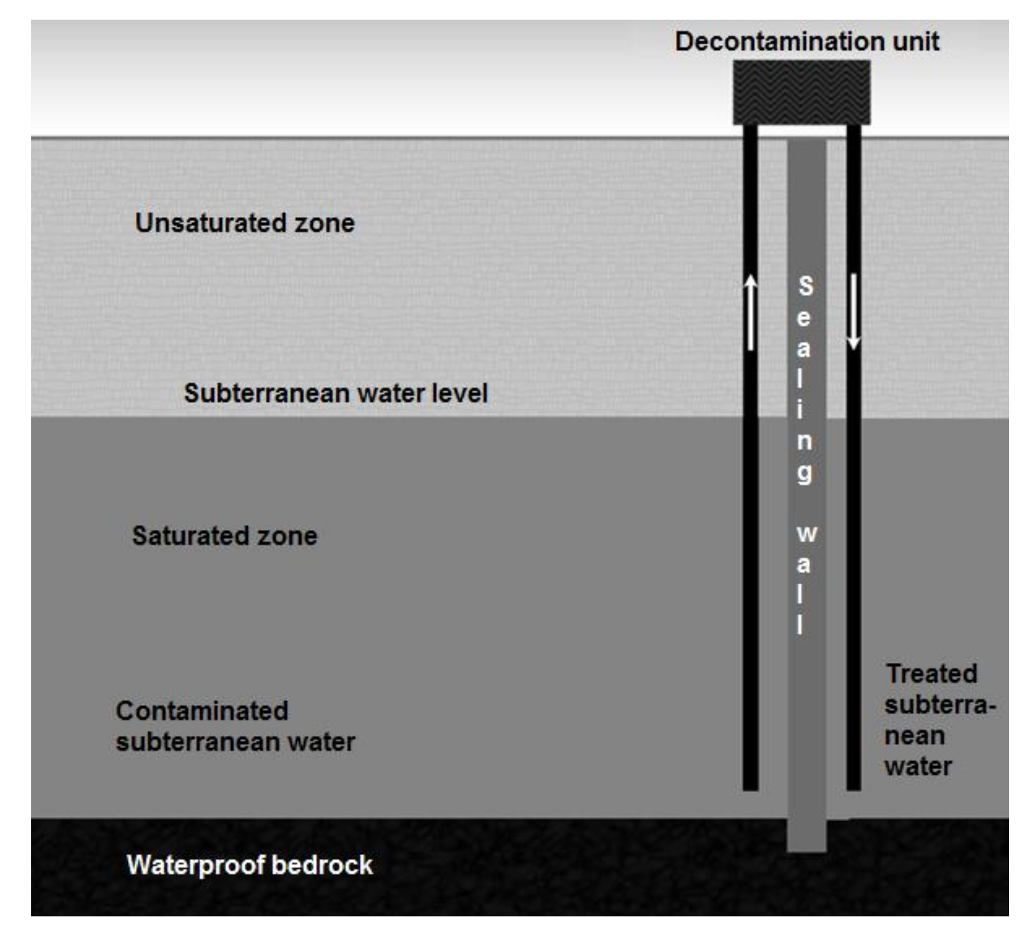
Simplified calculations have shown that the time needed for theoretical remediation of groundwater could be determined by the number of used modular EC units. The total time could be divided into a corresponding number of treatment campaigns with a duration of six months during late spring, the entire summer, and early autumn—this might provide a theoretical scenario for the treatment of contaminated groundwater in the area. It would of course require other idealistic assumptions, such as avoiding mixing of treated and untreated water, diluting of contaminated water with rainwater, undisturbed groundwater flow, etc. Such an environment-friendly approach might help in the development of a strategy for Zlaty potok (Golden Creek) site remediation. An example of a proposed groundwater remediation strategy can be seen on
Figure 6.


