Article

A New Method to Prepare Stable Polyaniline Dispersions for Highly Loaded Cathodes of All-Polymer Li-Ion Batteries

by
Elena Tomšík
1,*,†,
Daniil R. Nosov
2,3,†,
Iryna Ivanko
1,
Václav Pokorný
1,
Magdalena Konefał
1,
Zulfiya Černochová
1,
Krzysztof Tadyszak
1,
Daniel F. Schmidt
2 and
Alexander S. Shaplov
2
1
Institute of Macromolecular Chemistry AS CR, Heyrovského Nám. 2, Prague 6, 162 00 Prague, Czech Republic
2
Luxembourg Institute of Science and Technology (LIST), 5 Avenue des Hauts-Fourneaux, L-4362 Esch-sur-Alzette, Luxembourg
3
Department of Physics and Materials Science, University of Luxembourg, 2 Avenue de l’Université, L-4365 Esch-sur-Alzette, Luxembourg
*
Author to whom correspondence should be addressed.
These authors contributed equally to this work.
Polymers 2023, 15(11), 2508; https://doi.org/10.3390/polym15112508
Submission received: 20 March 2023 / Revised: 15 May 2023 / Accepted: 27 May 2023 / Published: 29 May 2023

Abstract

:
A new method for the preparation of polyaniline (PANI) films that have a 2D structure and can record high active mass loading (up to 30 mg cm−2) via acid-assisted polymerization in the presence of concentrated formic acid was developed. This new approach represents a simple reaction pathway that proceeds quickly at room temperature in quantitative isolated yield with the absence of any byproducts and leads to the formation of a stable suspension that can be stored for a prolonged time without sedimentation. The observed stability was explained by two factors: (a) the small size of the obtained rod-like particles (50 nm) and (b) the change of the surface of colloidal PANI particles to a positively charged form by protonation with concentrated formic acid. The films cast from the concentrated suspension were composed of amorphous PANI chains assembled into 2D structures with nanofibrillar morphology. Such PANI films demonstrated fast and efficient diffusion of the ions in liquid electrolyte and showed a pair of revisable oxidation and reduction peaks in cyclic voltammetry. Furthermore, owing to the high mass loading, specific morphology, and porosity, the synthesized polyaniline film was impregnated by a single-ion conducting polyelectrolyte-poly(LiMn-r-PEGMm) and characterized as a novel lightweight all-polymeric cathode material for solid-state Li batteries by cyclic voltammetry and electrochemical impedance spectroscopy techniques.

1. Introduction

The role of lithium in the global economy is increasing as green energy is introduced. The acceleration of decarbonization leads to a high demand for lithium, with metal being the most important raw material for the production of modern electronics and electric vehicles (lithium-ion batteries and energy storage systems). With the economy recovering in 2021 and electric vehicle sales rising, the Li metal price has increased throughout the year and will remain high for the next decade. According to the U.S. Geological Survey (USGS) Mineral Commodity Summaries (MCS), although known lithium deposits have significantly increased in number worldwide, the general quantity of Li is limited and will be consumed by 2050 (for mineral ores) if the rate of consumption remains unchanged [1]. Thus, the decrease in amount of Li in batteries and the increase in capacity and gravimetric energy density remains crucial and represents an important topic for scientific studies [2,3].
Currently, the typical cathode materials used in commercial lithium ion batteries are mainly represented by inorganic compounds such as LiFePO4 (LFP) [4], LiCoO2 [5], LiNiO2 [6], LiNiMnCoO2 (NMC), etc. In spite of the benefits, all of them have drawbacks: relatively low specific capacity and poor electronic and ionic conductivity are known for LiFePO4 [7], LiCoO2 is very expensive, and LiNiO2 possesses a weak stability. One of the suggested solutions to solve some of the above-mentioned drawbacks was the application of electrochemically active electron-conducting polymers (EAECPs) into the LFP, NMC, etc., cathode structure to replace the conventional conductive carbons, improving the electronic conductivity and mechanical properties of cathode materials [7,8]. Later on, to decrease the Li amount in batteries, EAECPs were suggested to solely substitute the inorganic metal oxide cathode materials [9,10]. The theoretical values of conducting polymers specific capacity are comparable with those of metal oxide electrodes, while their synthesis is easier and significantly less expensive. Among semiconducting polymers, polyaniline (PANI) is uniquely attractive from an economic standpoint. The monomer is commercially available with a low price, the polymer can be synthesized via one step simple reactions, and the obtained PANI dispersions can be stabilized for storage and subsequent realization [11]. The most known method for PANI synthesis is the chemical oxidation of aniline by ammonium peroxydisulfate in the presence of organic or inorganic acids [12]. The perchloric acid-doped PANI nanotubes have already shown promising results when they were applied as sole cathode materials in lithium/polymer rechargeable batteries [13]. The charge–discharge curves demonstrated good reversibility with an average discharge–plateau voltage of 3.0 V and an average charge–plateau voltage of 3.4 V. The highest discharge capacity of PANI nanotubes/nanofibers-based Li batteries reached 75.7 mA h g−1 out of 147 mA h g−1 theoretically calculated capacity [13]. However, such loss in capacity and unsatisfactory performance of neat PANI as a cathode material explained the strong agglomeration of the PANI chains, and the inaccessibility of interior of the resultant nanotubes with respect to ion intercalation/penetration [14]. Therefore, the modification of the PANI synthesis and its molecular self-assembly at the cathode is desirable.
Recently, our group [15,16], in parallel with the team of George Chen [16], demonstrated that PANI chains could be specifically assembled in 3D structures with 80% crystallinity by chemical polymerization of aniline in the presence of Hoffmeister ions. The intercalation of ions into such PANI 3D structures occurs much faster compared to the agglomerated state of common PANI. However, the limitation of this method was the mass loading of PANI that can be achieved on a current collector. The simple layer deposition resulted in the formation of thin films (~100–200 nm) that demonstrated excellent results in sensor applications [17]. However, the attempts to increase the thickness of the PANI layer via layer-by-layer deposition led to only 1–5 mg cm−2 of PANI mass loading [15]. A maximum of 2.4 mg cm−2 of PANI mass loading on the conductive carbon cloth electrode was realized after multiple sequential polymerization deposition steps [16,18,19].
In the present study, we report a very simple and clean one-step reaction route for the synthesis of a stable PANI suspension (Scheme 1), whose deposition on fluorine-doped tin oxide-coated (FTO) glass or conductive carbon cloth (CC) current collectors lead to a never-before-achieved record high mass loading of electro-active material (30 mg cm−2). The resulting PANI film possesses a 2D structure, as confirmed by X-ray diffraction measurements, and shows significant porosity, as observed via SEM. This structure was found to be ideal for impregnation by solutions of single ion conducting polyelectrolytes (SPEs), leading to the formation of an attractive composite cathode material and facilitating ion intercalation during charging and discharging processes.

2. Materials and Methods

2.1. Materials

Formic acid (>88%, Aldrich, St. Louis, MO, USA), ammonium peroxydisulfate (99%, Lach-ner, Neratovice, The Czech Republic), ethyl alcohol (99.8%, Aldrich), aniline (99+%, analytic grade, Lach-ner), poly(ethylene glycol)methyl ether methacrylate (PEGM, Mn = 500 g/mol, Aldrich), 3-sulfopropyl methacrylate potassium salt (98%, Aldrich), lithium hydride (LiH, 97%, Sigma-Aldrich), trifluoromethanesulfonamide (97%, ABCR, Karlsruhe, Germany), triethylamine (TEA, Et3N, ≥99%, Merck, Rahway, NJ, USA), lithium bis(trifluoromethylsulfonyl)imide (99+%, ABCR), 4-cyano-4-(phenylcarbonothioylthio)pentanoic acid (CPAD, chain transfer agent (CTA), >97%, Aldrich), dichloromethane (DCM, 99.8%, Aldrich), dimethylformamide (DMF, anhydrous, 99.5%, Acros, Waltham, MA, USA), N-methyl-2-pyrrolidone (NMP, anhydrous, 99.5%, Acros), diethyl ether (99%, Aldrich), methanol (99.8%, Aldrich), and tetrahydrofuran (THF, anhydrous, Acros) were used as received. Thionyl chloride (99.7% Acros) was distilled over linseed oil. 2,2′-Azobisisobutyronitrile (AIBN, initiator, 98%, Acros) was recrystallized from methanol. 4-Methoxyphenol (99%, Acros) was sublimed in a vacuum prior to use.
Fluorine-doped tin oxide-coated glass slides (FTO, SnO2/F, Aldrich, 100 × 100 × 2.2 mm3, surface resistivity 7 Ω/sq) were placed in an ultrasonic bath with acetone for 15 min, then with ethanol for 15 min and with water for 15 min. The slides were dried with N2 flow and in vacuum oven at 60 °C/1 mbar for 4 h before polyaniline coating. Carbon cloth (CC, Elat®, Fuel Cells Etc. Co., Bryan, TX, USA, ELAT-hydrophilic plain cloth, 3 × 4 cm2, 13 mg cm−2 80% porosity, 99.5% carbon content) was washed with ethanol in ultrasonic bath for 15 min, then with distilled water and dried in a vacuum oven at 60 °C/1 mbar for 4 h before PANI-a and PANI-c deposition.

2.2. Synthesis of Polyaniline via Acid-Assisted Polymerization (PANI-a)

Acid-assisted polymerization was carried out in one step in the presence of ammonium peroxydisulfate following the procedure described below. Aniline (0.510 g, 0.50 mL, 5.5 mmol) was dissolved at room temperature in 4.7 mL of concentrated formic acid and 1 mL of ethanol. Ammonium peroxydisulfate (0.094 g, 0.4 mmol) was dissolved in 1 mL of distilled water and was added dropwise into the solution of aniline. The molar ratio of monomer (aniline) to oxidant was 1.0:0.076. The polymerization was continued at room temperature for 48 h and UV-VIS spectroscopy was used to determine the completeness of the reaction (absence of monomer). After the evaporation of formic acid and ethanol, polyaniline (PANI-a) was obtained as a dark green powder. Polymer was washed with ethanol and the product was dried at 60 °C/1 mbar for 10 h. Yield: 0.522 g (99%, with protonation by HCOOH equal to 5%); Raman (785 nm laser): 1590, 1500, 1350, 1260, 1175 cm−1; σ = 0.41 ± 0.02 S cm−1 (25 °C).
The same procedure was repeated for the deposition of PANI-a film on the current collector. After completeness of polymerization, the resulting PANI dispersion was directly deposited either on the surface of the FTO glass slide or on CC with slow (!) solvent evaporation at room temperature to form a thin PANI-a film. The resultant film was rinsed with ethanol (to remove the oxidant residue) and dried at 60 °C for 2 h. For electrochemical characterization the total amount of PANI-a was 60 mg, which corresponds to 30 mg cm−2.

2.3. Synthesis of Polyaniline via Common Chemical Polymerization (PANI-c)

Polyaniline (PANI-c) was prepared in accordance with the previously published method [16]. In brief, aniline (0.10 mL, 0.001 mol, 0.04 mol L−1) was dissolved in a 12.5 mL of 5 M aqueous formic acid mixed with NaCl (6.092 g, 6.4 mol L−1). The aniline solution was cooled down to 5 °C in the ice bath and the solution of ammonium peroxydisulfate (0.224 g, 0.41 mmol, 0.04 mol L−1) in 12.5 mL of 5 M formic acid mixed with NaCl (6.092 g, 6.4 mol/L) was added to it dropwise. The total volume of the polymerization solution reached 25 mL. The reaction continued at 5 °C for 60 min, whereupon the obtained dispersion was deposited on FTO or CC surface. To obtain the film with active mass loading of PANI-c equal to 2.5 mg cm−2, four sequential polymerization reactions were carried out (4 PANI layers were deposited). The resultant film was rinsed with ethanol (to remove the oxidant residue) and dried at 60 °C for 2 h.

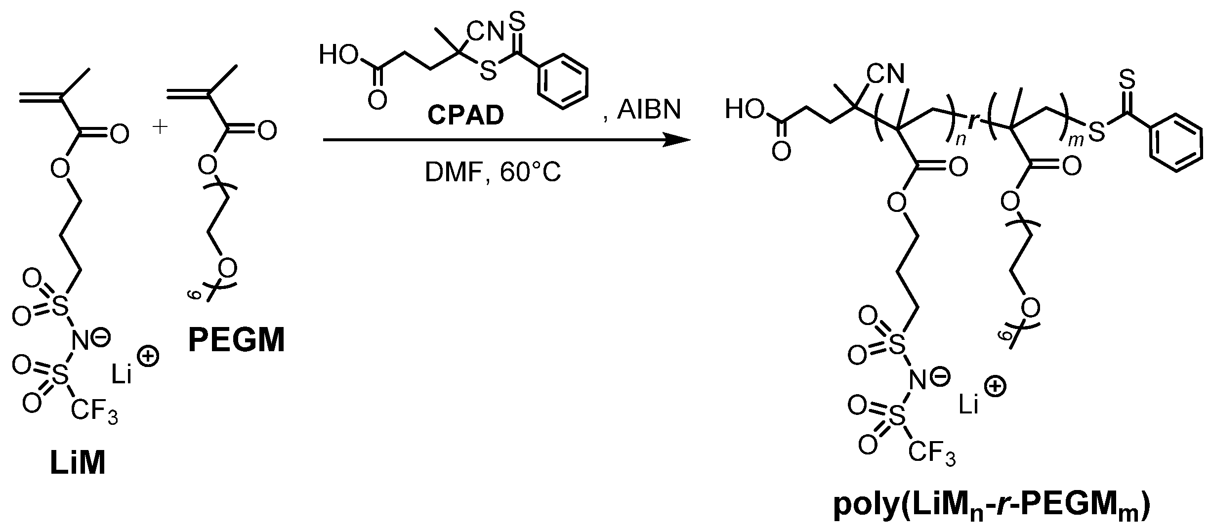
2.4. Synthesis of Lithium 1-[3-(methacryloyloxy)propylsulfonyl]-1-(trifluoromethanesulfonyl)imide (LiM)

Lithium 1-[3-(methacryloyloxy)propylsulfonyl]-1-(trifluoromethanesulfonyl)imide was synthesized in accordance with the procedures published previously [20,21]. The monomer was crystallized from anhydrous dichloromethane, and the resultant crystalline powder was dried at 25 °C/1 mbar overnight and stored under inert atmosphere in an argon-filled glove-box (MBRAUN MB-Labstar, H2O and O2 content < 0.5 ppm). Spectroscopic data of the target compound were in full accordance with those reported in the literature [22].

2.5. Synthesis of Random Poly(LiM13-r-PEGM81) Copolymer

Random copolymer poly(LiM13-r-PEGM81) was prepared via controlled RAFT copolymerization following the procedure given below.
PEGM (14.48 g, 28.97 mmol) and LiM (2.00 g, 5.79 mmol) were dissolved in 52.4 mL (49.45 g) of anhydrous DMF at room temperature under inert atmosphere, whereupon the AIBN (11.50 mg, 70.15 μmol) and CPAD (98.00 mg, 350.73 μmol) were added, and the stirring was continued until the formation of a clear pink solution. The following initial reagent ratios were loaded: ([PEGM]0 + [LiM]0):[CPAD]0:[AIBN]0 = 99.1:1:0.2. The solution was quantitatively transferred to the Schlenk flask equipped with magnetic stirring bar, degassed by three freeze–evacuate–thaw cycles, flashed with argon, and placed in the bath preheated to 60 °C. Polymerization was continued at 60 °C for 44 h. The resultant viscous solution was cooled down to RT, diluted with DMF, and precipitated into the excess of diethyl ether. Copolymer was collected, redissolved in acetone with the addition of 4-methoxyphenol (polymerization inhibitor, 40 mg), and precipitated for the second time into the excess of diethyl ether. The product in form of a pink viscous cold flowing liquid was collected and dried at 55 °C/0.1 mbar for 12 h in B-585 oven (Buchi Glass Drying Oven, Flawil, Switzerland) and filled with P2O5. Yield: 13.30 g (81.0%). The total conversion determined by 1H NMR: q = 0.96. The ratio between LiM and PEGM in the copolymer was determined by 1H NMR as 1:6.2 by mol; 1H NMR (600 MHz, DMSO-d6): δ = 3.89–4.20 (t, 14H, -CO-O-CH2), 3.38–3.87 (m, 212H, -CH2-O-CH2-CH2-O-), 3.24 (s, 18.6H, -O-CH3), 3.00 (s, 2H, -CH2-SO2-N-SO2CF3), 1.25–2.20 (m, 16H, -CH2-CH2-SO2-N-SO2CF3, -CH2-C(CH3)), 0.50–1.24 (m, 22H, -CH2-C(CH3)); 19F NMR (565 MHz, DMSO-d6): δ = −79.8 (s, CF3); 7Li NMR (233.2 MHz, DMSO-d6): δ = −1.03 (s, Li); IR (ATR-mode): 2947 (m, νC-H), 2872 (s, νC-H), 1723 (vs, νC=O), 1475 (m), 1451(m), 1404 (m), 1379 (w), 1352 (m, νasSO2), 1326 (w), 1265 (m), 1246 (m), 1227 (m), 1179 (s, νCF), 1105 (vs, νasC-O-C), 1055 (s, νCF), 947 (m), 858 (s, νsC-O-C), 842 (s), 789 (w), 749 (w) cm−1; Mn(SEC) = 43.7 kDa, Mw/Mn(SEC) =1.53; Tg = −53 °C (DSC 5 °C min−1); Tonset = 150 °C (TGA, 5 °C min−1, on air); σDC = 4.1 × 10⁻⁷ S cm−1 (25 °C).

2.6. Preparation of SPE/PANI-a@CC Composite Polymer Cathode

The coating of PANI-a deposited on carbon cloth (hereinafter abbreviated as PANI-a@CC), as described in Section 2.2., was used for further preparation of the composite cathode by its uniform impregnation with the 0.1 wt.% solution of poly(LiM13-r-PEGM81) in anhydrous NMP. The poly(LiM13-r-PEGM81) solution was filtered through 0.22 μm syringe filter and cast at room temperature on top of PANI-a@CC placed on the leveled hotplate, whereupon the surface of the hotplate was heated to 70 °C. The as-obtained cathode tape was further dried in an oven at 70 °C/1 mbar for 24 h.

2.7. Measurements

NMR spectra were recorded on Avance III HD 600 MHz spectrometer (Bruker, Mannheim, Germany) at 25 °C in the indicated deuterated solvent and are listed in ppm. The signals corresponding to the residual protons and carbons of the deuterated solvent were used as an internal standard for 1H and 13C NMR, respectively. The C6F6 (−164.9 ppm) and LiBF4 (−1.04 ppm) were utilized as external standards for 19F and 7Li NMR, correspondingly. Raman spectra were registered on an InVia™ microspectrometer (Renishaw plc, Wotton-under-Edge, UK) equipped with a DM LM microscope (Leica microsystems, Wetzlar, Germany). The spectra were measured with two excitation lasers: Ag laser (514 nm excitation) and NIR diode laser (785 nm excitation) with gratings 2400 and 1200 lines mm–1, respectively. IR spectra were acquired on an INVENIO-R Fourier-transform IR-spectrometer (Bruker, Germany) using ATR technology with 128 scans and a resolution of 2 cm−1. The electron paramagnetic resonance (EPR) measurements were conducted with ELEXSYS 540 X band spectrometer (Bruker, Germany) equipped with 049X microwave bridge (Super X) and ER4108 TMHS slim design resonator (Bruker, Germany). The following EPR spectrometer settings were applied for the experiments: 6.362 mW (15 dB) microwave power; 0.1 G (L-3) and 1 G (M-10) modulation amplitude; 100 kHz frequency modulation; 5.12 ms time constant; 20.48 ms conversion time; 60 dB gain; resolution of 2048 points and at temperature of 295 K. G-factors were estimated by comparison with DPPH free radical standard, assuming that g-factor is equal to 2.0036. Line asymmetry was defined as the ratio of positive amplitude (A) to the absolute value of the negative amplitude (|B|) of the first derivative of resonant microwave absorption recorded in EPR.
The size exclusion chromatography (SEC) was used to determine the number-average molecular weight (Mn(SEC)) and Mw/Mn ratio for ionic random poly(LiM13-r-PEGM81). The study was performed on a 1200 Infinity gel permeation chromatograph (Agilent Technologies, Santa Clara, CA, USA) equipped with PLgel 5 μm MIXED-D column (Agilent Technologies, USA), PLgel 5 μm (Agilent Technologies) pre-column and an integrated refractive index detector. The system was operated at 50 °C and 1.0 mL/min flow using 0.1 M Li(CF3SO2)2N solution in DMF as an eluent. Poly(methyl methacrylate) standards (EasiVial PM, Agilent Technologies, Mp = 550–1558 × 103) were used to perform calibration.
Thermogravimetric analysis (TGA) was carried out in air on a TGA2 STARe System (Mettler Toledo, Greifensee, Switzerland) by applying a heating rate of 5 °C min−1. The onset weight loss temperature (Tonset) was determined as the point in the TGA curve at which a significant deviation from the horizontal was observed. The resulting temperature was then rounded to the nearest 1 °C. For DSC measurements, the polymer sample was preliminary dried at 60 °C/1 mm Hg for 12 h in the B-585 oven (Buchi Glass Drying Oven, Switzerland), filled with P2O5, and was transferred under a vacuum inside an argon-filled glovebox (MBRAUN MB-Labstar, H2O and O2 content < 0.5 ppm), where it was hermetically sealed in Al pans. Prior to measurements, the calorimeter was calibrated using the indium calibration standard (Mettler-Toledo, purity > 99.999%). The DSC of polymer sample was performed on a DSC3+ STARe System (Mettler Toledo, Switzerland) with a heating rate of 5 °C min−1 (1st and 2nd cycles) and 10 °C min−1 (3rd cycle) in the range of −80 to 80 °C. The glass transition temperature (Tg) was determined during the second heating cycle, as the first one was used to eliminate the thermal history of the sample.
Diffraction patterns were obtained using a high-resolution diffractometer Explorer (GNR Analytical Instruments, Novara, Italy) equipped with a 1D silicon strip detector Mythen 1K (Dectris, Baden, Switzerland). A sealed X-ray tube operated at 40 kV, 35 mA, and monochromatized with Ni foil (β filter) was used to produce CuKα radiation (wavelength λ = 1.54 Å). Measurements were performed in the range 2θ = 2–35° with 0.1° step and an exposure time of 10 s at each step.
Static and Dynamic Light Scattering (SLS and DLS). The intensity-weighted hydrodynamic radius (RH) and scattering intensity of the PANI-a samples in the form of formic acid solutions were studied at 20 °C as a function of scattering angle using ALV-6000 equipment (ALV-GmbH, Langen, Germany). The data were processed with the Repes algorithm [23]. The weight average molecular mass ( M w ¯ ) and radii of gyration ( R g ¯ ) for PANI particles were determined at 20 °C by SLS method using the same ALV-6000 equipment. The z-average radii of gyration of particles ( R g ¯ ) and their Mw were calculated from a wide range of scattering angles (20° to 150°, increment 2°) and polymer concentrations (6.0, 5.45, 5.0, and 4.5 µg mL−1 in the solution of formic acid). All solutions were filtered using 0.46 µm PVDF syringe filter prior investigations. The SLS was measured three times and the SLS acquisition time was 90 s. Subsequently, the Guinier correlations were plotted from the obtained data and analyzed by the ALV/static and Dynamic FIT and PLOT 4.31 10/01 software ((ALV-GmbH, Germany).
Electrochemical impedance spectroscopy (EIS) was applied to determine the ionic conductivity (σDC) of poly(LiM13-r-PEGM81) copolymer using a VSP potentiostat/galvanostat (Bio-Logic Science Instruments, Seyssinet-Pariset, France). To avoid any influence of moisture/humidity on the conductivity of polymer electrolyte, the latter was preliminary dried at 60 °C/1 mbar for 12 h in the B-585 oven (Buchi Glass Drying Oven, Switzerland) filled with P2O5 and transferred under a vacuum inside an argon-filled glovebox (MBRAUN MB-Labstar, H2O, and O2 content < 0.5 ppm). The polymer was sandwiched between two stainless steel (SS-316) blocking electrodes. The distance between the electrodes was kept equal to 250 µm using a Teflon spacer ring with the inner area of 0.502 cm2. The symmetrical stainless steel/copolymer/stainless steel assembly was clamped into the 2032 coin cell and was then taken out from the glovebox. Cell impedance was measured at the open circuit potential (OCP) by applying a 10 mV perturbation in the frequency range from 10−2 to 2 × 10⁵ Hz and in a temperature range from 20 to 100 °C. Temperature was controlled using the programmed KT-53 oven (Binder, Tuttlingen, Germany), where cells were allowed to reach thermal equilibrium for at least 1 h before each test.
Electrochemical characterization of the neat electrodes (PANI-a@CC and PANI-c@CC) was carried out by cyclic voltammetry (CV) in 0.2 M aq. HCl liquid electrolyte. The CV was performed at 25 °C in three electrodes cell configuration using an AUTOLAB PGSTAT302N potentiostat (Metrohm Inula GmbH, Prague, Czech Republic) with a FRA32M Module and Nova 2.1 software. A Pt sheet (1.2 cm2) was used as the counter electrode, and the Ag/AgCl wire was applied as the pseudo-reference electrode. The potential sweeps were carried out between −0.1 and 0.8 V vs. Ag+/Ag at variable scan rates.
The CV of SPE/PANI-a@CC composite cathodes was performed in both liquid electrolyte and in a solid state. (1) The CV in liquid electrolyte was recorded using the three-electrode cell (CC as working, Pt foil as counter, and Ag/AgCl wire as the reference electrodes) in 2.0 M lithium bis(trifluoromethylsulfonyl)imide (LiTFSI) solution in a mixture of ethylene carbonate/dimethyl carbonate with a ratio of 1:1 by volume. The CV was measured at 25 °C on AUTOLAB PGSTAT302N potentiostat (Metrohm Inula GmbH, Czech Republic) in the potential window ranging from −0.9 to 1.0 V vs. Ag+/Ag with various scan rates. (2) For the CV in solid state, the Li||SPE/PANI-a@CC||Cu cell was assembled inside the glovebox (MBRAUN MB-Labstar, H2O and O2 content < 0.5 ppm). Li foil was used as a reference and counter electrode, and SPE/PANI-a@CC was used as a working electrode. The hermetically sealed cell was taken out of the glovebox, placed in the heating oven for 1 h at 70 °C for conditioning, and then tested by cyclic voltammetry applying 1 mV s−1 sweep rate at 70 °C. Five continuous cycles were performed and recorded.
The EIS for SPE/PANI-a@CC composite cathodes were measured in liquid electrolyte and in a solid state on AUTOLAB PGSTAT302N potentiostat (Metrohm Inula GmbH, Czech Republic), applying the frequency range from 10−1 to 10−4 Hz with 5 mV perturbation. All measurements were performed at an open circuit potential (OCP). (1) The EIS in liquid electrolyte was carried out at 25 °C using 2.0 M LiTFSI solution in a mixture of ethylene carbonate/dimethyl carbonate with a ratio of 1:1 by volume. (2) For the EIS in solid state, the SPE/PANI-a@CC cathode was sandwiched between two stainless steel (SS-316) blocking electrodes inside an argon-filled glovebox (MBRAUN MB-Labstar, H2O, and O2 content < 0.5 ppm). The distance between the electrodes was kept equal to 250 µm using a Teflon spacer ring with the inner area of 0.502 cm2. The symmetrical stainless steel||SPE/PANI-a@CC||stainless steel assembly was clamped into a 2032 coin cell and was taken out from glovebox afterwards. The EIS was further measured at 25 and 70 °C. To reach the equilibrium, the corresponding temperature was applied for 2 h before the measurement.

3. Results and Discussions

3.1. Synthesis of Polyaniline via Formic Acid-Assisted Polymerization (PANI-a)

Several synthetic techniques have been applied to obtain organized PANI film for different applications (sensors, electro-magnetic shielding, pseudo-capacitors, and batteries). These techniques include chemical oxidation, electrochemical polymerization [24], template-assisted chemical method [25], interface polymerization [26], etc. The chemical oxidation of aniline has been conducted in the presence of various dopant acids (hydrochloric acid (HCl) [27,28], sulfuric acid (H2SO4) [29,30], o-amino benzoic acid [31], dodecylbenzene sulfonic acid [32], formic acid [33], acetic acid (AA) [30], malic acid (MA) [34], propionic acid (PA) [34], succinic acid (SA) [34], tartaric acid (TA) [34], citric acid (CA) [34], (etc.) and oxidants (ammonium persulfate (APS), vanadic acid [35], hydrogen peroxide (H2O2) [36], potassium dichromate (K2Cr2O7) [37], iron(III) chloride (FeCl3) [38], potassium permanganate (KMnO4) [39], etc.). The nature of the acid used is believed to be of high importance, as it simultaneously acts as a dopant and as a structure-directing agent. Both the acidity of the medium and its concentration affect the morphology of the synthesized PANI, varying from flowers, sheets [27], and plates [40] to nanotubes [34,41], nanorodes [35], and nanofibers [27]. In contrast to oxidative chemical polymerization, where the ratio of aniline monomer: ammonium peroxydisulfate is 1:1 or 1:1.25 [41], the acid-assisted aniline polymerization is suggested to be a radical process, which was proved by measuring EPR signal for freshly mixed polymerization solution (SI, Figure S1). Although the acid-assisted polymerization of aniline has been known (see [42,43,44]), here we report a significantly improved method with the utilization of concentrated formic acid, proceeding at room temperature without the need for cooling. The process consists of the addition of aqueous ammonium peroxydisulfate solution to the solution of aniline in the mixture of concentrated formic acid and ethanol (Scheme 1). The optimization of the process allowed to us establish the optimal monomer/initiator ratio equal to 13:1, leading to the formation of a stable PANI suspension. The video of the synthetic process is shown in the Supporting Information (Video S1). From the initiation centers the reaction starts with the formation of dark blue colored oligomers, and 30 min at ambient temperature results in the dark green PANI suspension (Figure S1 and Video S1). It was found that the concentration of the formic acid plays a crucial role for the stability of the suspension due to the interaction with polymer chains via protonation as it was previously shown for another polymer-poly (3,4-ethylene dioxythiophene) (PEDOT) [44]. The concentration of the PANI in suspension was only limited by the amount of added monomer. With the increase in aniline concentration, the reaction proceeded faster.
The obtained PANI suspension was very stable without any precipitation for at least six months and the PANI mass loading on the current collector surface could be further controlled by changing either the deposition volume of the suspension and/or by dilution of the suspension with concentrated formic acid or any other organic solvent with the exception for water, which leads to the immediate coagulation (precipitation) of PANI.

3.2. Study of PANI-a Suspension via Dynamic (DLS) and Static Light Scattering (SLS)

The PANI-a suspension was studied via dynamic (DLS) and static light scattering (SLS) analyses. During DLS measurements of PANI-a colloid suspension at different angles, structures with a hydrodynamic radius of 50 nm were detected. The distribution of their sizes depicted as a 3D diagram (Figure 1a) demonstrated unimodal character.
The equal-area representation (the Z-axis shows RH·A(RH), where A(RH) is the intensity-weighed distribution function of hydrodynamic radii RH of particles in the sample) was applied for plotting Figure 1a. The results indicated that the 50 nm PANI-a particles were fairly stable in terms of colloidal homogeneity, showing practically no coalescence and sedimentation. The dependence of decay rate Γ vs. the square of the scattering vector q (Figure 1b) demonstrated linear character and approached above zero when crossing the y-axis. This can serve as proof of the rotational diffusion of these particles. The results of SLS and DLS experiments are presented in Table 1. The value of v = RH/Rg = 1.718 can be ascribed to the elongated rod-like shape of the particles similar to those rod-type structures observed for block copolymers obtained from N-(2-hydroxypropyl)-methacrylamide and N-(2N′-Boc-aminoethyl)acrylamide in aqueous solution [45]. The key role of the presented new synthetic method for PANI-a synthesis is the possibility to obtain stable PANI suspension with high concentration and without addition of any soluble polyelectrolyte. The observed stability can be explained by two factors: (a) the small size of the obtained rod-like particles (50 nm) and (b) the change of the surface of colloidal PANI particles to a positively charged form by protonation with concentrated formic acid. These conclusions can be additionally proved by comparison with PANI-c synthesis, where the concentration of the weak formic acid is not enough to efficiently modify the PANI surface charge, and the agglomeration and sedimentation of the particles are observed within a few minutes from the start of reaction.

3.3. PANI-a Physical and Electrochemical Properties

The newly obtained PANI suspension (denoted as PANI-a) and coatings on FTO and CC (herein and after-mentioned as (PANI-a@FTO and PANI-a@CC) were characterized by a set of methods and further compared with the PANI prepared by “common” oxidation method (denoted as PANI-c). The “Roadmap” of the experiments is shown in Scheme 2. It must be emphasized that PANI-c has been reported in the literature [16] and is shown in the current study only for comparison purposes.

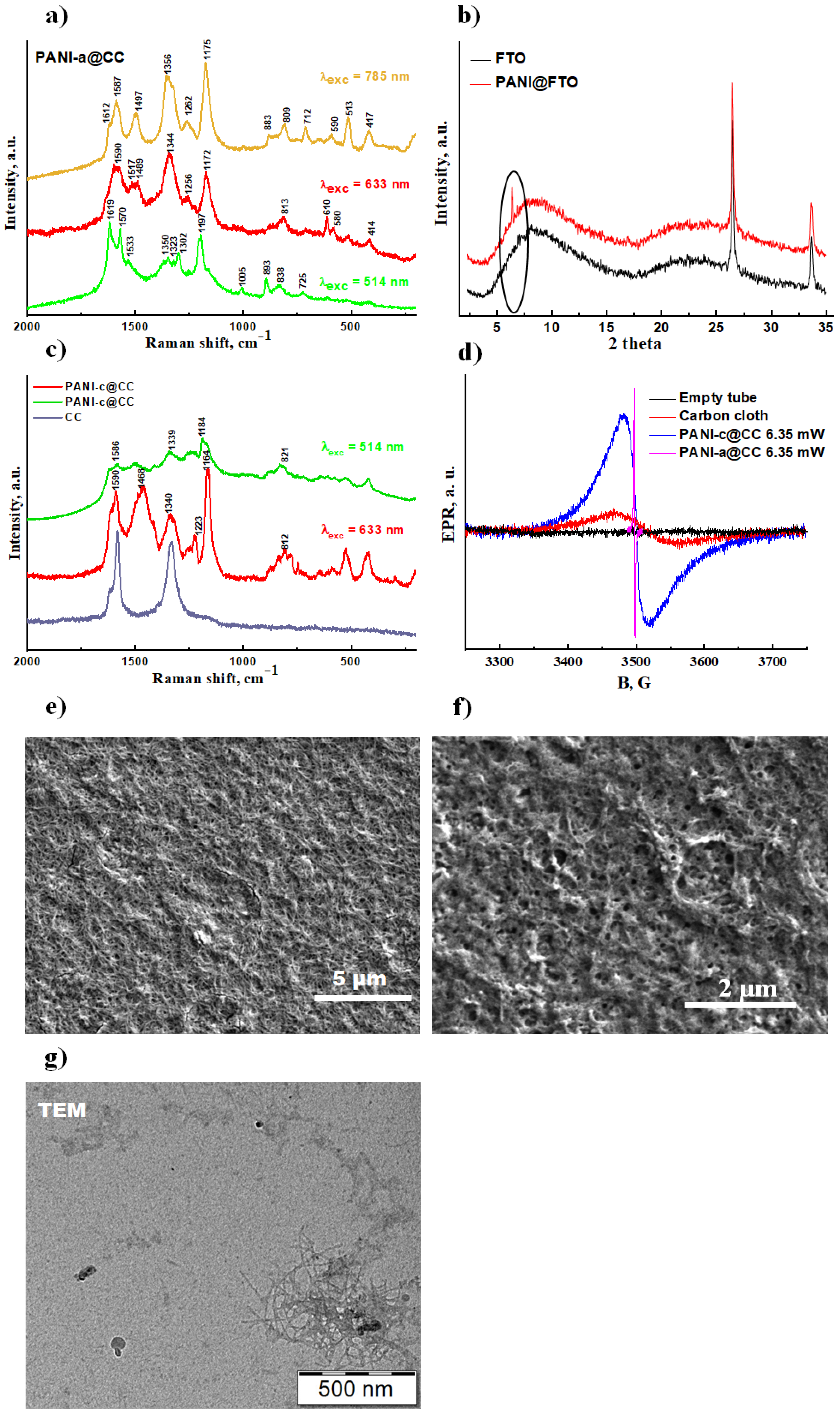
3.3.1. Spectroscopic Characterization

Raman spectra were measured with excitation lines of 785 and 633 nm, and spectra for both PANI-a@CC and PANI-c@CC were found to be identical regardless of the excitation laser. Figure 2a shows the Raman spectrum for PANI-a@CC, while the spectrum of PANI-c@CC is presented in Figure 2c for comparison. The position and intensities of the main peaks in PANI-a@CC confirmed the formation of polyaniline at the surface of the CC (Figure 2a). The band at 1590 cm–1 was assigned to the C=C stretching vibration and the band at 1500 cm–1—to the C=N stretching vibration in the quinoid ring. The band linked with the C stretching vibration of the C~N+ delocalized polaron structure was observed at 1350 cm–1. The relatively high intensity was previously ascribed to the formation of charge transfer between PANI and carbonaceous material [46]. The characteristic band for C–N stretching in benzene rings was found at 1260 cm–1. The sharp intensive peak at 1175 cm–1 was attributed to the deformation C-H vibrations in the semi-quinoid rings. The band at 810 cm–1 was assigned to the ring deformation vibration of the protonated structures [46,47]. As the Raman excitation line of 785 and 633 nm is known to be in resonance with the quinoid units of PANI [48], additional Raman spectrum was measured with the excitation line of 514 nm (Figure 2a). In contrast to spectra recorded with the 785 and 633 nm excitation lasers, the band associated with the C~C vibrations in the benzenoid rings at 1619 cm–1 substantially shifted and its intensity significantly increased when spectrum was measured with the excitation 514 nm line. The novel band associated with the ring vibrations of the quinoid units appeared at 1570 cm–1. Another new band at 1350 cm−1 was subsequently assigned to the delocalization of the polaron in the C~N+ structure. The band corresponding to the vibration of secondary amine was observed at 1302 cm–1. Finally, the band at 1197 cm–1 was assigned to the C–H deformation vibrations in the rings [48,49]. Based on the Raman data analysis, it can be concluded that PANI-a has a chemical structure similar to PANI-c, although the mechanisms of the synthesis are different.

3.3.2. X-ray Diffraction Studies

The XRD analysis for PANI-a was performed on the film deposited on FTO glass (PANI-a@FTO) and the result is shown in Figure 2b. The obtained diffraction patterns revealed broad humps at 2Θ = 9° and 23°, as well as two intense peaks at 2Θ = 26.51° and 33.71° (corresponding to (110) and (101) planes, respectively), originated from the FTO substrate [50]. The difference in the XRD patterns consisted of a sharp peak at 2Θ = 6.41° and was attributed to neat PANI-a (Figure 2b). According to the literature [51,52], this peak corresponds to interplanar spacing d = 13.8 Å and is associated with the distance between two stacks in the 2D stacking arrangement of polymer chains created by the intervening dopant ions. Another difference relates to a slight increase in intensity of a broad reflection at about 2Θ = 22°, which is characteristic for amorphous PANI films and is attributed to the scattering from polymer chains due to π-π stacking interactions [53].
In contrast to PANI-a, the XRD pattern of PANI-c on the FTO glass exhibited several diffraction peaks [16,54]. The position of these peaks indicates the strong interchain packing, and clearly defined scattering refers to high crystallinity of the film [44]. The indexation of the respective reflections has been performed before by various authors (see for example [31]). Analyzing the XRD data, it can be concluded that PANI-a has 2D stacking arrangement of polymer chains together with the amorphous phase, in contrast to PANI-c, which possesses a high degree of crystallinity (up to 70%) [19].

3.3.3. Electronic Paramagnetic Resonance (EPR)

To reveal further difference in the physical properties of PANI-a and PANI-c polymers, they were deposited on the conductive carbon cloth (CC) and the electronic paramagnetic resonance (EPR) was performed (Figure 2d). In the selected recording conditions, the resonator with an empty tube showed no signal. The neat CC showed a weak EPR Dyson line (ΔBPANI-a = 73.7 G, A/|B| = 1.6, b = 0.23) and it was the main reason for the decrease in the resonator’s Q-factor. The PANI-a@CC demonstrated very narrow linewidth (ΔBPANI-a = 0.87 G), large line asymmetry (A/|B|), which for multiple samples varied in the range 1.33–1.43, and g-factor equal to 2.0009 ± 0.0005. In comparison with PANI-a@CC, the PANI-c@CC showed a significantly wider linewidth ΔBPANI-c = 34.7 G, smaller line asymmetry A/|B| in the range 1.08–1.34, b = 0.11, and nearly the same g-factor equal to 2.0003 ± 0.0005 (Figure 2d and Figures S2–S7). As both PANI-a and PANI-c polymers are conductive to the line asymmetry, A/|B| started to appear in the spectrum. This asymmetry is considered to be typical for conductive polymers where the gradient of microwaves penetrates the skin depth of the sample due to the skin effect. This results in the asymmetrical shape of the Dyson line detected in EPR spectroscopy. The asymmetry ratio A/|B| depends on specific conductivity and on the thickness and homogeneity of the sample on the CC. For two samples exhibiting the same specific conductivity, the thicker and more homogeneous polymer layer will cause larger line asymmetry [55,56]. The equal values of the g-factors found for both PANI-a@CC and PANI-c@CC samples are typical for materials that have free radicals and/or conductive electrons. The largest difference between the two polymers was observed in the linewidth, which differed 40 times. It is of common knowledge [57] that the line width is inversely proportional to the relaxation times ( 1 T 2 ~ Δ B ), which in its turn allows for the assumption that the dissipation of microwave energy is faster for PANI-c polymer and the saturation effects will appear for higher microwave powers (Figures S3–S7). Thus, the EPR results are in good agreement with the measured XRD data (Figure 2b).
It is important to note that CC is visible in the background of the PANI-c spectrum for samples with minor deposition of the PANI-c polymer. The amplitude ratio (PANI-c/CC) is 6.3:1, the intensity ratio is ~3.3:1, and the linewidth ratio is ~2.1:1. In contrast to PANI-c, the CC signal in PANI-a sample was not detectable at all (Figure 2d). The Dyson lines were fitted with modified Dyson line [58] equations (Equations (1)–(5)):
y = A · ( f 1 + f 2 ) + y 0
f 1 = ( b · ( 1 p 2 ) 2 p ) ( 1 + p 2 ) 2    
  f 2 = ( b · ( 1 q 2 ) 2 q ) ( 1 + q 2 ) 2
p = ( x x 0 ) w
q = ( x + x 0 ) w
where A is the amplitude, w—linewidth, b—function defined asymmetry parameter (0 is assigned for symmetrical parameter), x0—resonance field, y0—constant (Table 2).

3.3.4. Scanning (SEM) and Transmission Electron (TEM) Microscopies

The microstructure of PANI-a was examined via scanning electron microscopy (SEM) on the FTO glass slides (Figure 2e,f). According to the SEM image, the PANI-a has nanofibrillar morphology similar to that reported for PANI-c [44], with higher porosity. The size of nanofibrillar can be estimated as 200 nm–1 μm. The observed porosity will play a crucial role in the impregnation of PANI-a film with solid polymer electrolyte, as it will be shown during the formation of a cathode material (see Section 3.5 below).
The transmission electron analysis (TEM) was carried out for PANI-a suspension on Pt-grid (Figure 2g). The TEM image clearly demonstrates the formation of the nanofibrils. Therefore, it can be concluded that during the suggested acid-assisted polymerization in highly concentrated acidic medium the synthesized PANI chains are assembled into 2D structures with nanofibrillar morphology. The size of the latter according to TEM analysis can be estimated as 100–150 nm, which is lower than that determined by SEM (200 nm–1 μm) and higher than that calculated with the results of DLS (50 nm, see Section 3.2). The difference in the nano-objects size between these methods can be driven by different sample preparations: while the DLS/SLS measurements were performed using the as prepared or diluted suspensions, the SEM/TEM analysis was conducted for the PANI-a films, where the particles were agglomerating and collapsing during the casting and drying process. In DLS, we measured swollen particles directly in the suspension and, therefore, DLS is a more precise method for determining the particle size of PANI-a as it measures the particles in their natural state close to the solution.

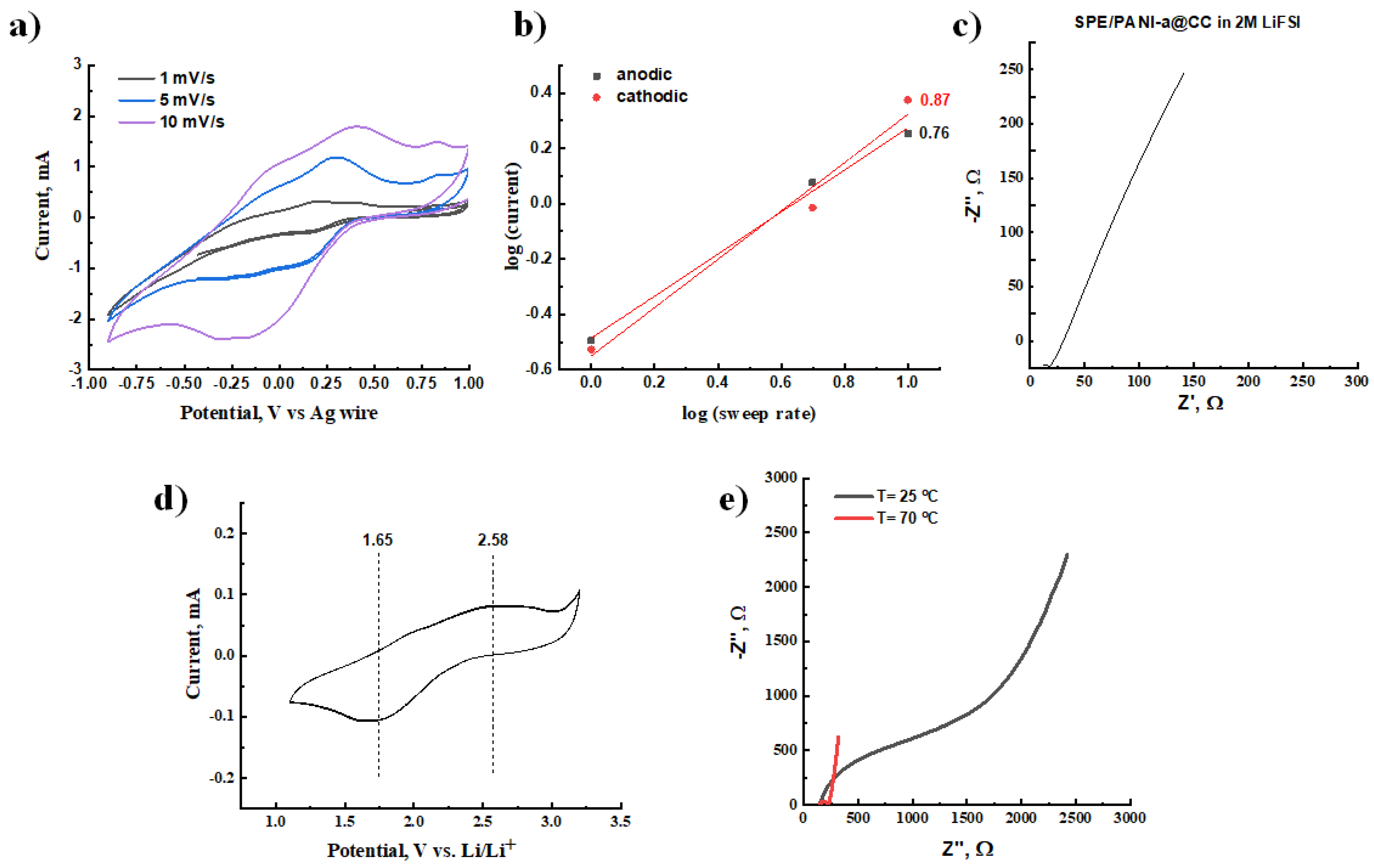
3.3.5. Cyclic Voltammetry (CV) and Electrochemical Impedance Spectroscopy (EIS)

The electrochemical performance of the PANI-a@CC was first investigated by cyclic voltammetry, varying the scan rates in the range from 10 to 100 mV s−1, and was further compared with the data obtained for PANI-c@CC (Figure 3). It is important to note that PANI-a film was deposited with the polymer mass loading of 30 mg cm−2, while PANI-c had only 2.5 mg cm−2 mass loading. As discussed above, this difference in the mass loading is connected with the limitations of each synthesis/deposition method. The PANI-a@CC film clearly demonstrated the symmetrical cyclic voltammetry curves independently of the scan rate applied (Figure 3a,b). The CV curves of PANI-a@CC demonstrated the presence of two oxidations and two reductions peaks that we found to be revisable. The cyclic voltammetry measurements for PANI-a@CC revealed that the separation between anodic and cathodic peaks is equal to 120 mV for the first pair and 30 mV for the second pair (Figure 3b). Moreover, the deposited high mass loading of PANI-a has dependences of the log (peak current) for the anodic and cathodic currents vs. the log (sweep rate), with their slopes approaching unity (Figure 3c).
According to previous investigations, the shape of the EAECPs cyclic voltammograms, the position, and the number of the redox peaks were found to be influenced by the macromolecular arrangements, and more importantly by the interactions between polymer chains (see [16,44]). As discussed above, the XRD data (Figure 2b) showed that PANI-a possesses 2D structure incorporated into the amorphous phase that can clearly explain its unique electrochemical performance despite the high polymer mass loading. In contrast to PANI-a, the PANI-c@CC film, despite its significantly lower polymer mass loading (2.5 mg cm−2), showed the dependences of the log (peak current) for the anodic and cathodic currents vs. the log (sweep rate) with the slopes of 0.71 and 0.74, respectively (Figure 3e). Moreover, the oxidations and reductions peaks observed for PANI-a@CC were absent on the CV curves of PANI-c@CC, having had an almost rectangular shape (Figure 3a,d). It can be concluded that the simultaneous possession of 2D organization and amorphous phase in PANI-a leads to faster oxidation and reduction in comparison with PANI-c, having a compact crystalline-like structure. The calculated slopes of the log (peak current) vs. the log (sweep rate) dependence additionally prove that the intercalation (diffusion) of ions into the PANI-a film is happening much faster than in the PANI-c electrode (Figure 3c,e).

3.4. Synthesis and Characterization of Solid Polymer Electrolyte (SPE)

Copolymerization of lithium 1-[3-(methacryloyloxy)propylsulfonyl]-1-(trifluoromethanesulfonyl)imide (LiM) with poly(ethylene glycol)methyl ether methacrylate (Scheme 3) was performed via controlled reversible addition fragmentation chain-transfer polymerization (RAFT) using AIBN and 4-cyano-4-(phenylcarbonothioylthio)pentanoic acid (CPAD) as an initiator and chain transfer agent, respectively [22,59]. Synthesis was carried out with the conversion of 96%, as determined by H1 NMR, and resulted in the preparation of poly(LiM13-r-PEGM81) having Mn(SEC) = 43700 Da and satisfactory Mw/Mn ratio (1.53). The composition, purity, and chemical structure of the obtained copolymer were supported by 1H, 19F, 7Li NMR, and FTIR spectroscopies. The isolated poly(LiM13-r-PEGM81) represented pink highly viscous cold flowing liquid with a low glass transition temperature equal to −53 °C, as determined by DSC. The investigation of its ionic conductivity in anhydrous conditions provided σDC value of 4.1 × 10⁻⁷ S cm−1 at 25 °C. The electrochemical stability window of the poly(LiM13-r-PEGM81) copolymer was studied by cyclic voltamperometry at 70 °C in Li||polymer||Cu configuration and the results are presented in Figure S8. The ESW of poly(LiM13-r-PEGM81) was found to be 4.3 V versus Li+/Li.

3.5. Composite PANI-a/SPE Cathode Material: Preparation and Testing

The cyclic voltammetry measurements of PANI-a@CC clearly demonstrated that electrochemical processes were not limited by diffusion, even when thick PANI-a film with a high mass loading of polymer was tested. This observation opened up possibilities to apply PANI-a not only as a promoter of electronic conductivity in addition to common inorganic LFP or NMC materials, but also as an original complete cathode material. Moreover, with the aim to enhance safety and to create an all-polymer-based battery, the PANI-a@CC was further combined with ionically conductive poly(LiM13-r-PEGM81). The impregnation of the single-ion conducting solid polymer electrolyte (SPE) was performed through the deposition of its NMP solution on the surface of PANI-a@CC with subsequent drying. The unique porous 2D stacking arrangement of PANI-a polymer chains allowed for the perfect penetration of SPE macromolecules and their mutual intercalation inside the SPE/PANI-a@CC electrode. This novel cathode material was tested by cyclic voltammetry and electrochemical impedance spectroscopy in 3-electrode cell configuration, wherein the results are presented in Figure 4a.
The CV examination of SPE/PANI-a@CC electrode was performed in 3-electrode configuration, using 2 M LiTFSI solution in a mixture of ethylene carbonate/dimethyl carbonate (1:1 by volume) as an electrolyte (Figure 4a). Moreover, the LiTFSI containing electrolyte was chosen with additional purpose to demonstrate the high levels of accessibility of the SPE/PANI-a layer to Li+ ions insertion/diffusion. Due to the nature of the selected liquid electrolyte, it was possible to increase the limits of the potential window, and the testing was carried out in the range from −0.9 V to 1 V vs. pseudo-reference Ag wire electrode. Several scan rates from 1 to 10 mV s−1 were applied to reveal the level of SPE and PANI-a intercalation. It was observed that both oxidation and reduction currents were increased proportionally with the acceleration of the scan rate, which can serve as a proof perfect SPE impregnation and that no SPE layer was blocking the surface of the PANI network. Moreover, the dependencies of the log (peak current) for the anodic and cathodic currents vs. the log (sweep rate) decreased slightly (0.76 for anodic and 0.87 cathodic, see Figure 4b) compared to the electrodes without SPE (Figure 3c). It can be concluded that the impregnation of PANI via drop casting of SPE solution did not block the surface of PANI. However, the impregnation/deposition process can still be optimized to fully utilize the electrochemical performance of PANI.
The charge transfer resistance, which is defined as a measure of the difficulty encountered when an electron is shifted from one atom in PANI macromolecule to another atom or to current collector, was estimated for SPE/PANI-a@CC electrode by electrochemical impedance spectroscopy (Figure 4c). In the SPE/PANI-a@CC composite cathode, the charge transfer resistance can happen between the SPE and PANI or PANI and CC interfaces. The measurement was performed at open circuit potential and at 25 °C. Figure 4c clearly demonstrates that the EIS curve does not have any semi-circle, which is the characteristic feature of the charge transfer resistance between PANI/SPE. Such a shape allows us to conclude that the newly obtained PANI-a structure/morphology is ideal for its impregnation by the solution of a single ion conducting polyelectrolyte and leads to the formation of an attractive composite cathode material with low charge transfer resistance.
To ensure the ability of the SPE/PANI-a@CC composite cathode to work with Li metal, the cyclic voltammetry of a Li||SPE/PANI-a@CC||Cu cell was studied at 70 °C (Figure 4d). The CV showed two broad symmetrical peaks at 2.58 and 1.65 V vs. Li/Li+. These peaks correspond to oxidation and reduction reactions, respectively. The maintenance of their shape and position upon cycling (5 continuous cycles) clearly demonstrates that the doping/de-doping processes are reversible [60]. The total obtained ESW of 2.1 V vs. Li/Li+ fully coincided with the stability window (2.4 V vs. Li/Li+) of a cathode composed of perchloricacid-doped PANI nanotubes [13]. To further show the potential of the SPE/PANI-a@CC cathode to work in all-solid-state batteries, its impedance was measured between two stainless steel plates in the absence of any liquid electrolyte at 25 and 70 °C (Figure 4e). The temperatures of experiment were selected by the following reasons: (a) solid state polymer Li batteries typically operate at elevated temperatures (70 °C); (b) given the unstable nature of many conducting polymers, it is important to demonstrate that PANI provides stable performance at elevated temperatures (70 °C) required by batteries. The total impedance of the SPE/PANI-a@CC in a solid state at 25 °C showed an increase in comparison with the measurement performed for the same material in 2 M LiTFSI liquid electrolyte (Figure 4c). However, this can be leveled by an increase in temperature to 70 °C and the enhancement of the ion’s mobility and conductivity in SPE, leading to a decrease in both the real and imaginary parts of the impedance spectra (Figure 4e).

4. Conclusions

A novel method for the synthesis of polyaniline (PANI) via acid-assisted polymerization in concentration solution has been proposed for the first time. The physical and electrochemical properties of the obtained PANI-a were studied in detail and compared with the PANI-c prepared by the well-known oxidative polymerization procedure. The most striking advantages of PANI-a can be summarized as follows: (1) the polymer is formed in a form of stable suspension that consists of rod-like particles with a size of 50 nm and stabilized by the formation of the positively charged form via the protonation with concentrated formic acid; (2) the deposition of the concentrated PANI-a suspension of FTO glass slides or carbon cloth surface results in never-before-achieved record high mass loading of electro-active material (30 mg cm−2); (3) the deposited PANI-a chains are amorphous and assembled into 2D structures with nanofibrillar morphology; (4) the PANI-a film shows very fast and efficient diffusion of the ions through its body, as proved by the presence of two revisable oxidation and reduction peaks in cyclic voltammetry; (5) the morphology and porosity of PANI-a film allows for its impregnation with the solid polymer electrolytes and leads to the formation of all-polymer-based cathode materials with excellent electrochemical performance and a promising capacity for future application in supercapacitors and batteries.

Supplementary Materials

The following supporting information can be downloaded at: https://www.mdpi.com/article/10.3390/polym15112508/s1, Figure S1: Normalized EPR signal of polymerization mixture (PANI-a) immediately after preparation (t = 0) and after 24 h; Video S1: synthesis of PANI suspension by acid-assisted polymerization; Figure S2: EPR spectra of carbon cloth used as support for polymer synthesis and empty tube; Figure S3: Microwave room temperature saturation experiment of PANI-a@CC and PANI-c@CC polymer; Figure S4: EPR spectra of PANI-c polymer covering carbon cloth, carbon cloth recorded separately and the difference spectrum of only PANI-c polymer without carbon cloth contribution. Figure S5: EPR line of carbon cloth and the fit with modified Dyson line; Figure S6: EPR line of PANI-c polymer after subtraction of carbon cloth and the fit with modified Dyson line; Figure S7. EPR line of PANI-a polymer and the fit with modified Dyson line; Figure S8: Electrochemical stability windows obtained by CV for poly(LiM-r-PEGM) solid polymer electrolyte at 70 °C (stainless steel as a working electrode and Li foil as counter and reference electrodes, scan rate 0.2 mV s−1).

Author Contributions

Conceptualization, E.T. and A.S.S.; methodology, I.I.; SPE synthesis, D.R.N. and A.S.S.; XRD, V.P.; data analysis, M.K.; SLS and DLS analysis, Z.Č.; EPR analysis, K.T.; writing—original draft preparation, E.T. and D.R.N.; writing—review and editing, E.T., A.S.S. and D.F.S.; supervision, E.T. and A.S.S.; project administration, E.T.; funding acquisition, E.T. All authors have read and agreed to the published version of the manuscript.

Funding

This research was funded by Czech Health Research Council (grant number NU20–06–00424)-synthesis of PANI samples, cathode preparation and investigation and in part was supported by the Luxembourg National Research Fund (FNR) through ANR-FNR project DISAFECAP (agreement number INTER/ANR/19/13358226)–synthesis of LiM monomer and random poly(LiM13-r-PEGM81) copolymer.

Institutional Review Board Statement

Not applicable.

Data Availability Statement

The data presented in this study are available on request from the corresponding author.

Acknowledgments

Authors would like to warmly thank Benoit Marcolini (LIST) and Régis Vaudemont (LIST) for their help and advices related to materials characterization.

Conflicts of Interest

The authors declare the following financial interest/personal relationships which may be considered as potential competing interests: Elena Tomsik reports financial support was provided by Czech Health Research Council, NU20-06-00424.

References

  1. Ore, I.; Pigments, I.O.; Rock, P.; Crystal, Q.; Earths, R.; Ash, S. Mineral Commodity Summaries 2021; U.S. Geological Survey: Reston, VA, USA, 2021; ISBN 9781411343986.
  2. Meister, P.; Jia, H.; Li, J.; Klöpsch, R.; Winter, M.; Placke, T. Best Practice: Performance and Cost Evaluation of Lithium Ion Battery Active Materials with Special Emphasis on Energy Efficiency. Chem. Mater. 2016, 28, 7203–7217. [Google Scholar] [CrossRef]
  3. Canepa, P.; Sai Gautam, G.; Hannah, D.C.; Malik, R.; Liu, M.; Gallagher, K.G.; Persson, K.A.; Ceder, G. Odyssey of Multivalent Cathode Materials: Open Questions and Future Challenges. Chem. Rev. 2017, 117, 4287–4341. [Google Scholar] [CrossRef] [PubMed]
  4. Xiao, L.; Chen, X.; Cao, R.; Qian, J.; Xiang, H.; Zheng, J.; Zhang, J.G.; Xu, W. Enhanced performance of Li|LiFePO4 cells using CsPF6 as an electrolyte additive. J. Power Sources 2015, 293, 1062–1067. [Google Scholar] [CrossRef]
  5. Oz, E.; Altin, S.; Demirel, S.; Bayri, A.; Altin, E.; Baglayan, O.; Avci, S. Electrochemical effects and magnetic properties of B substituted LiCoO2: Improving Li-battery performance. J. Alloys Compd. 2016, 657, 835–847. [Google Scholar] [CrossRef]
  6. Zheng, X.; Li, X.; Wang, Z.; Guo, H.; Huang, Z.; Yan, G.; Wang, D. Investigation and improvement on the electrochemical performance and storage characteristics of LiNiO2-based materials for lithium ion battery. Electrochim. Acta 2016, 191, 832–840. [Google Scholar] [CrossRef]
  7. Chepurnaya, I.; Smirnova, E.; Karushev, M. Electrochemically Active Polymer Components in Next-Generation LiFePO4 Cathodes: Can Small Things Make a Big Difference? Batteries 2022, 8, 185. [Google Scholar] [CrossRef]
  8. Chung, Y.M.; Ryu, K.S. Surface coating and electrochemical properties of LiNi0.8Co0.15Al0.05O2/polyaniline composites as an electrode for Li-ion batteries. Bull. Korean Chem. Soc. 2009, 30, 1733–1737. [Google Scholar] [CrossRef]
  9. Kotz, R.; Carlen, M. Principles and applications of electrochemical capacitors. Electrochim. Acta 2000, 45, 2483–2498. [Google Scholar] [CrossRef]
  10. Zhang, L.; Zhao, X.S. Carbon-based materials as supercapacitor electrodes. Chem. Soc. Rev. 2009, 38, 2520–2531. [Google Scholar] [CrossRef]
  11. Miller, J.; Burke, A. Electrochemical Capacitors: Challenges and Opportunities for Real-World Applications. Electrochem. Soc. Interface 2008, 17, 53. [Google Scholar] [CrossRef]
  12. Simon, P.; Gogotsi, Y. Materials for electrochemical capacitors. Nat. Mater. 2008, 7, 845–854. [Google Scholar] [CrossRef]
  13. Cheng, F.Y.; Tang, W.; Li, C.; Chen, J.; Liu, H.; Shen, P.; Dou, S. Conducting Poly(aniline) Nanotubes and Nanofibers: Controlled Synthesis and Application in Lithium/Poly(aniline) Rechargeable Batteries. Chem. Eur. J. 2006, 12, 3082–3088. [Google Scholar] [CrossRef]
  14. Rudge, A.; Raistnck, I.A.N.; Gottesfeld, S.; Ferraris, J. A Study of The Electrochemical Properties of Conducting Polymers for Application in Capacitors. Electrochim. Acta 1994, 39, 273–287. [Google Scholar] [CrossRef]
  15. Peng, C.; Hu, D.; Chen, G.Z. Theoretical specific capacitance based on charge storage mechanisms of conducting polymers: Comment on ‘Vertically oriented arrays of polyaniline nanorods and their super electrochemical properties’. Chem. Commun 2011, 47, 4105–4107. [Google Scholar] [CrossRef] [PubMed]
  16. Tomšík, E.; Ivanko, I.; Kohut, O.; Hromádková, J. High-Rate Polyaniline/Carbon-Cloth Electrodes: Effect of Mass Loading on the Pseudocapacitive Performance. ChemElectroChem 2017, 4, 2884–2890. [Google Scholar] [CrossRef]
  17. Ismail, R.; Sedenkova, I.; Svoboda, J.; Lukesova, M.; Walterova, Z.; Tomsik, E. Acid-assisted polymerization: The novel synthetic route of sensing layers based on PANI films and chelating agents protected by non-biofouling layers for Fe2+ or Fe3+ potentiometric detection. J. Mater. Chem. B. 2023, 11, 1545–1556. [Google Scholar] [CrossRef]
  18. Tomšík, E.; Kohut, O.; Ivanko, I.; Pekárek, M.; Bieloshapka, I.; Dallas, P. Assembly and Interaction of Polyaniline Chains: Impact on Electro- and Physical-Chemical Behavior. J. Phys. Chem. C 2018, 122, 8022–8030. [Google Scholar] [CrossRef]
  19. Gospodinova, N.; Muat, V.; Kolev, H.; Romanova, J. New insight into the redox behavior of polyaniline. Synth. Met. 2011, 161, 2510–2513. [Google Scholar] [CrossRef]
  20. Shaplov, A.S.; Vlasov, P.S.; Armand, M.; Lozinskaya, E.I.; Ponkratov, D.O.; Malyshkina, I.A.; Vidal, F.; Okatova, O.V.; Pavlov, G.M.; Wandrey, C.; et al. Design and synthesis of new anionic “polymeric ionic liquids” with high charge delocalization. Polym. Chem. 2011, 2, 2609–2618. [Google Scholar] [CrossRef]
  21. Porcarelli, L.; Shaplov, A.S.; Salsamendi, M.; Nair, J.R.; Vygodskii, Y.S.; Mecerreyes, D.; Gerbaldi, C. Single-Ion Block Copoly(ionic liquid)s as Electrolytes for All-Solid State Lithium Batteries. ACS Appl. Mater. Interfaces 2016, 8, 10350–10359. [Google Scholar] [CrossRef]
  22. Lingua, G.; Grysan, P.; Vlasov, P.S.; Verge, P.; Shaplov, A.S.; Gerbaldi, C. Unique Carbonate-Based Single Ion Conducting Block Copolymers Enabling High-Voltage, All-Solid-State Lithium Metal Batteries. Macromolecules 2021, 54, 6911–6924. [Google Scholar] [CrossRef] [PubMed]
  23. Jakeš, J. Regularized Positive Exponential Sum (REPES) Program-A Way of Inverting Laplace Transform Data Obtained by Dynamic Light Scattering. Collect. Czechoslov. Chem. Commun. 1995, 60, 1781–1797. [Google Scholar] [CrossRef]
  24. Wu, J.; Zhang, Q.; Wang, J.; Huang, X.; Bai, H. A self-assembly route to porous polyaniline/reduced graphene oxide composite materials with molecular-level uniformity for high-performance supercapacitors. Energy Environ. Sci. 2018, 11, 1280–1286. [Google Scholar] [CrossRef]
  25. Wu, C.; Bein, T. Conducting Polyaniline Filaments in a Mesoporous Channel Host. Science 1994, 264, 1757–1759. [Google Scholar] [CrossRef]
  26. Sivakkumar, S.R.; Oh, J.S.; Kim, D.W. Polyaniline nanofibres as a cathode material for rechargeable lithium-polymer cells assembled with gel polymer electrolyte. J. Power Sources 2006, 163, 573–577. [Google Scholar] [CrossRef]
  27. Qiu, B.; Wang, J.; Li, Z.; Wang, X.; Li, X. Influence of Acidity and Oxidant Concentration on the Nanostructures and Electrochemical Performance of Polyaniline during Fast Microwave-Assisted Chemical Polymerization. Polymers 2020, 12, 310. [Google Scholar] [CrossRef]
  28. Qiu, B.; Li, Z.; Wang, X.; Li, X.; Zhang, J. Exploration on the Microwave-Assisted Synthesis and Formation Mechanism of Polyaniline Nanostructures Synthesized in Different Hydrochloric Acid Concentrations. Polym. Chem. 2017, 55, 3357–3369. [Google Scholar] [CrossRef]
  29. Hambitzer, G.; Stassen, I. Polymerization of aniline in aqueous sulfuric acid -study by electrochemical thermospray mass spectrometry. Synth. Met. 1993, 57, 1045–1050. [Google Scholar] [CrossRef]
  30. Trchova, M.; Sedenkova, I.; Stejskal, J.; Bok, J. Polymerization of Aniline in the Solutions of Strong and Weak Acids: The Evolution of Infrared Spectra and Their Interpretation Using Factor Analysis. Appl. Spectrosc. 2007, 61, 1153–1162. [Google Scholar]
  31. Rao, P.S.; Sathyanarayana, D.N. Synthesis of electrically conducting copolymers of aniline with o/m -amino benzoic acid by an inverse emulsion pathway. Polymer 2002, 43, 5051–5058. [Google Scholar]
  32. Kuramoto, N.; Tomita, A. Aqueous polyaniline suspensions: Chemical oxidative polymerization of dodecylbenzene-sulfonic acid aniline salt. Polymer 1997, 38, 3055–3058. [Google Scholar] [CrossRef]
  33. Gomes, E.C.; Oliveira, M.A.S. Chemical Polymerization of Aniline in Hydrochloric Acid (HCl) and Formic Acid (HCOOH) Media. Differences Between the Two Synthesized Polyanilines. Am. J. Polym. Sci. 2012, 2, 5–13. [Google Scholar] [CrossRef]
  34. Wu, W.; Pan, D.; Li, Y.; Zhao, G.; Jing, L.; Chen, S. Facile fabrication of polyaniline nanotubes using the self-assembly behavior based on the hydrogen bonding: A mechanistic study and application in high-performance electrochemical supercapacitor electrode. Electrochim. Acta 2015, 152, 126–134. [Google Scholar] [CrossRef]
  35. Li, G.; Jiang, L.; Peng, H. One-dimensional polyaniline nanostructures with controllable surfaces and diameters using vanadic acid as the oxidant. Macromolecules 2007, 40, 7890–7894. [Google Scholar] [CrossRef]
  36. Sun, Z.; Geng, Y.; Li, J.; Wang, F. Chemical polymerization of aniline with hydrogen peroxide as oxidant. Synth. Met. 1997, 84, 99–100. [Google Scholar] [CrossRef]
  37. Zoromba, M.S.; Alghool, S.; Abdel-Hamid, S.M.S.; Bassyouni, M.; Abdel-Aziz, M.H. Polymerization of aniline derivatives by K2Cr2O7 and production of Cr2O3 nanoparticles. Polym. Adv. Technol. 2017, 28, 842–848. [Google Scholar] [CrossRef]
  38. Yasuda, A.; Shimidzu, T. Chemical Oxidative Polymerization of Aniline with Ferric Chloride. Polymer 1993, 25, 329–338. [Google Scholar] [CrossRef]
  39. Ding, Q.; Qian, R.; Jing, X.; Han, J.; Yu, L. Reaction of aniline with KMnO4 to synthesize polyaniline-supported Mn nanocomposites: An unexpected heterogeneous free radical scavenger. Mater. Lett. 2019, 251, 222–225. [Google Scholar] [CrossRef]
  40. Ma, Y.; Zhang, H.; Hou, C.; Qiao, M.; Chen, Y.; Zhang, H. Multidimensional polyaniline structures from micellar templates. J. Mater. Sci. 2017, 52, 2995–3002. [Google Scholar] [CrossRef]
  41. Stejskal, J.; Sapurina, I.; Trchová, M.; Konyushenko, E.N.; Holler, P. The genesis of polyaniline nanotubes. Polymer 2006, 47, 8253–8262. [Google Scholar] [CrossRef]
  42. Chao, D.; Lu, X.; Chen, J.; Zhang, W.; Wei, Y. Anthranilic acid assisted preparation of Fe3O4-Poly(aniline-co-o-anthranilic acid) nanoparticles. J. Appl. Polym. Sci. 2006, 102, 1666–1671. [Google Scholar] [CrossRef]
  43. Ji, J.; Li, R.; Li, H.; Shu, Y.; Li, Y.; Qiu, S.; He, C.; Yang, Y. Phytic acid assisted fabrication of graphene/polyaniline composite hydrogels for high-capacitance supercapacitors. Compos. Part B Eng. 2018, 155, 132–137. [Google Scholar] [CrossRef]
  44. Tomšík, E.; Ivanko, I.; Svoboda, J.; Šeděnková, I.; Zhigunov, A.; Hromádková, J.; Pánek, J.; Lukešová, M.; Velychkivska, N.; Janisová, L. Method of Preparation of Soluble PEDOT: Self-Polymerization of EDOT without Oxidant at Room Temperature. Macromol. Chem. Phys. 2020, 221, 2000219. [Google Scholar] [CrossRef]
  45. Kolouchova, K.; Groborz, O.; Skarkova, A.; Brabek, J.; Rosel, D.; Svec, P.; Starcuk, Z.; Slouf, M.; Hruby, M. Thermo- and ROS-Responsive Self-Assembled Polymer Nanoparticle Tracers for 19 F MRI Theranostics. Biomacromolecules 2021, 22, 2325–2337. [Google Scholar] [CrossRef] [PubMed]
  46. Morávková, Z.; Trchová, M.; Tomšík, E.; Čechvala, J.; Stejskal, J. Enhanced thermal stability of multi-walled carbon nanotubes after coating with polyaniline salt. Polym. Degrad. Stab. 2012, 97, 1405–1414. [Google Scholar] [CrossRef]
  47. Rakić, A.A.; Vukomanović, M.; Ćirić-Marjanović, G. Formation of nanostructured polyaniline by dopant-free oxidation of aniline in a water/isopropanol mixture. Chem. Pap. 2014, 68, 372–383. [Google Scholar] [CrossRef]
  48. Bláha, M.; Trchová, M.; Morávková, Z.; Humpolíček, P.; Stejskal, J. Semiconducting materials from oxidative coupling of phenylenediamines under various acidic conditions. Mater. Chem. Phys. 2018, 205, 423–435. [Google Scholar] [CrossRef]
  49. Kiefer, W. Recent Advances in linear and nonlinear Raman spectroscopy I. J. Raman Spectrosc. 2007, 38, 1538–1553. [Google Scholar] [CrossRef]
  50. El-Bashir, S.M.; Yahia, I.S.; Binhussain, M.A.; AlSalhi, M.S. Design of Rose Bengal/FTO optical thin film system as a novel nonlinear media for infrared blocking windows. Results Phys. 2017, 7, 1852–1858. [Google Scholar] [CrossRef]
  51. Murugesan, R.; Subramanian, E. Effect of organic dopants on electrodeposition and characteristics of polyaniline under the varying influence of H2SO4 and HClO4 electrolyte media. Mater. Chem. Phys. 2003, 80, 731–739. [Google Scholar] [CrossRef]
  52. Pouget, J.P.; Oblakowski, Z.; Nogami, Y.; Albouy, P.A.; Laridjani, M.; Oh, E.J.; Min, Y.; MacDiarmid, A.G.; Tsukamoto, J.; Ishiguro, T.; et al. Recent structural investigations of metallic polymers. Synth. Met. 1994, 65, 131–140. [Google Scholar] [CrossRef]
  53. Buron, C.C.; Lakard, B.; Monnin, A.F.; Moutarlier, V.; Lakard, S. Elaboration and characterization of polyaniline films electrodeposited on tin oxides. Synth. Met. 2011, 161, 2162–2169. [Google Scholar] [CrossRef]
  54. Gospodinova, N.; Ivanov, D.A.; Anokhin, D.V.; Mihai, I.; Brun, S.; Romanova, J.; Tadjer, A. Unprecedented Route to Ordered Polyaniline: Direct Synthesis of Highly Crystalline Fibrillar Films with Strong p-p Stacking Alignment. Macromol. Rapid Commun. 2009, 30, 29–33. [Google Scholar] [CrossRef] [PubMed]
  55. Tadyszak, K.; Strzelczyk, R.; Coy, E.; Ma, M.; Augustyniak-jab, M.A. Size effects in the conduction electron spin resonance of anthracite and higher anthraxolite. Magn. Reson. Chem 2016, 54, 239–245. [Google Scholar] [CrossRef]
  56. Dyson, F. Electron Spin Resonance Absorption in Metals. II. Theory of Electron Diffusion and the Skin Effect. Phys. Rev. 1955, 98, 349–358. [Google Scholar] [CrossRef]
  57. Wertz, J.; Bolton, J. Electron Spin Resonance; Chapman and Hall: New York, NY, USA; London, UK, 1986; ISBN 9789401083072. [Google Scholar]
  58. Popovych, V.; Bester, M.; Stefaniuk, I.; Kuzma, M. Dyson line and modified Dyson line in the EPR measurements. Nukleonika 2015, 60, 385–388. [Google Scholar] [CrossRef]
  59. Lozinskaya, E.I.; Ponkratov, D.O.; Malyshkina, I.A.; Grysan, P.; Lingua, G.; Gerbaldi, C.; Shaplov, A.S.; Vygodskii, Y.S. Self-assembly of Li single-ion-conducting block copolymers for improved conductivity and viscoelastic properties. Electrochim. Acta 2022, 413, 140126. [Google Scholar] [CrossRef]
  60. Kozarenko, O.A.; Dyadyun, V.S.; Papakin, M.S.; Posudievsky, O.Y.; Koshechko, V.G.; Pokhodenko, V.D. Effect of potential range on electrochemical performance of polyaniline as a component of lithium battery electrodes. Electrochim. Acta 2015, 184, 111–116. [Google Scholar] [CrossRef]
Scheme 1. Acid-assisted polymerization of aniline in the presence of formic acid.
Polymers 15 02508 sch001
Figure 1. (a) Angular dependence of PANI-a 6 µg/mL in formic acid solution at room temperature; (b) Decay rate vs. square scattering vector dependence for PANI sample with a concentration of 6 mg mL−1 in formic acid.
Polymers 15 02508 g001
Scheme 2. Roadmap of the experimental part.
Polymers 15 02508 sch002
Figure 2. (a) Raman spectra of PANI-a on the carbon cloth (PANI-a@CC) recorded with excitation lines of 514, 633, and 785 nm; (b) XRD data for PANI-a deposited on FTO glass (PANI-a@FTO); (c) Raman spectra of PANI-c on the carbon cloth (PANI-c@CC) recorded with excitation lines of 514 and 633 nm; (d) Normalized EPR signal—a first derivative of resonant microwave absorption (arbitrary units) vs. the external magnetic field for PANI-a@CC and PANI-c@CC; (e,f) SEM of PANI-a@FTO film with different magnifications; (g) TEM of PANI-a suspension.
Polymers 15 02508 g002
Figure 3. (a) Cyclic voltammetry of PANI-a@CC measured with different scan rates in 0.2 M aq. HCl electrolyte using the three-electrode cell configuration at 25 °C; (b) Detailed CV of PANI-a@CC at 10 mV s−1 scan rate; (c) Dependence of the log(sweep rate) for PANI-a@CC; (d) Cyclic voltammetry of PANI-c@CC measured with different scan rates in 0.2 M aq. HCl in three-electrode cell configuration at 25 °C; (e) Dependence of the log(sweep rate) for PANI-c@CC.
Polymers 15 02508 g003
Scheme 3. Synthesis of poly(LiM-r-PEGM) solid polymer electrolyte.
Polymers 15 02508 sch003
Figure 4. (a) Cyclic voltammetry of SPE/PANI-a@CC electrode at different scan rates in 2 M LiTFSI solution in a mixture of ethylene carbonate/dimethyl carbonate (1:1 by volume) at 25 °C; (b) Dependence of the log(sweep rate) for SPE/PANI-a@CC electrode; (c) electrochemical impedance spectroscopy of SPE/PANI-a@CC electrode measured at open circuit potential at 25 °C in 2 M LiTFSI solution in a mixture of ethylene carbonate/dimethyl carbonate (1:1 by volume) at 25 °C; (d) Cyclic voltammetry of SPE/PANI-a@CC in Li||SPE/PANI-a@CC||Cu configuration cell at 1 mV s−1 at 70 °C; (e) electrochemical impedance spectroscopy of SPE/PANI-a@CC electrode at 25 and 70 °C, measured in a solid state between two steel plates.
Polymers 15 02508 g004
Table 1. SLS and DLS results of PANI-a suspension in formic acid.
RH,0
(nm) 1
Rg,app
(nm)
Mw app × 108
(g mol−1)
Dapp × 1015
(cm2 s−1)
v
56.8 ± 11.497.6 ± 19.57.3 ± 1.52.89 ± 0.0751.72
1 RH,0 is the hydrodynamic radius at zero angle, Rg,app is the radius of gyration of rod-type particles, Mw app is the weight average particles molecular weight, and Dapp is the collective diffusion coefficient, calculated as the slope angle of the curve in Figure 1.
Table 2. Fitting parameters with modified Dyson line.
SampleA,
(arb. u.)
w,
(G)
b,
(abr. u.)
A/|B|x0,
(G)
Carbon cloth0.1673.70.331.63503.9
PANI-c1.1934.70.111.08–1.343497.9
PANI-a14.100.870.231.33–1.433497.4
Disclaimer/Publisher’s Note: The statements, opinions and data contained in all publications are solely those of the individual author(s) and contributor(s) and not of MDPI and/or the editor(s). MDPI and/or the editor(s) disclaim responsibility for any injury to people or property resulting from any ideas, methods, instructions or products referred to in the content.

