
Morphological Transformation in Polymer Composite Materials Filled with Carbon Nanoparticles: Part 1—SEM and XRD Investigations

 , ,
, , 
Abstract
:1. Introduction
2. Materials and Methods
3. Results
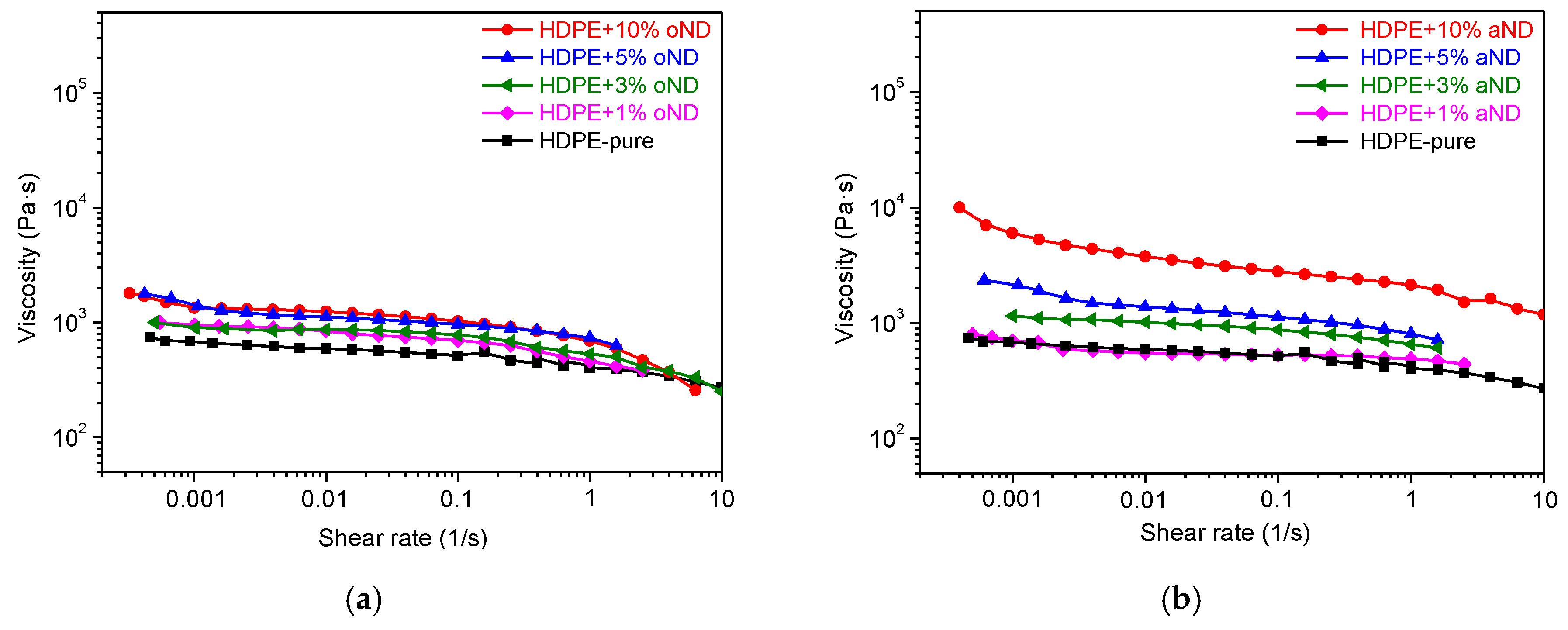
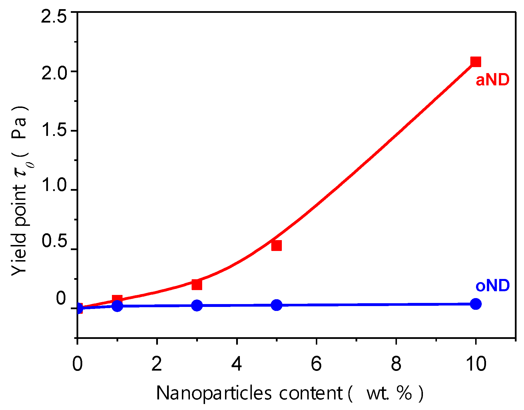
3.1. Rheology
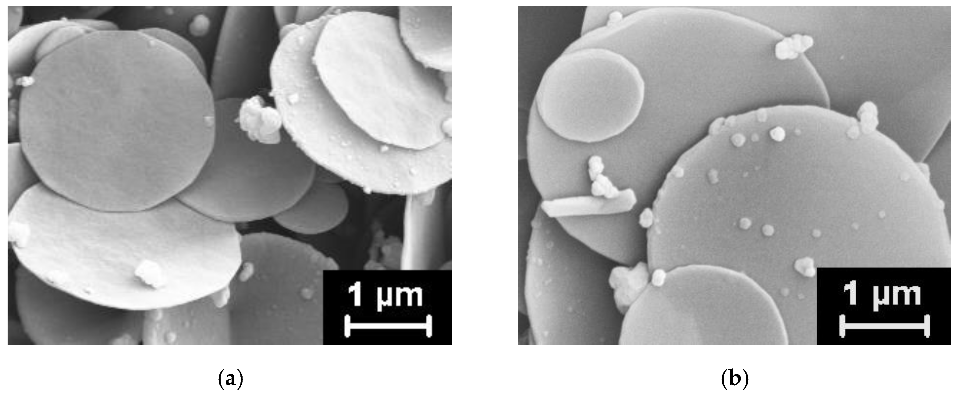
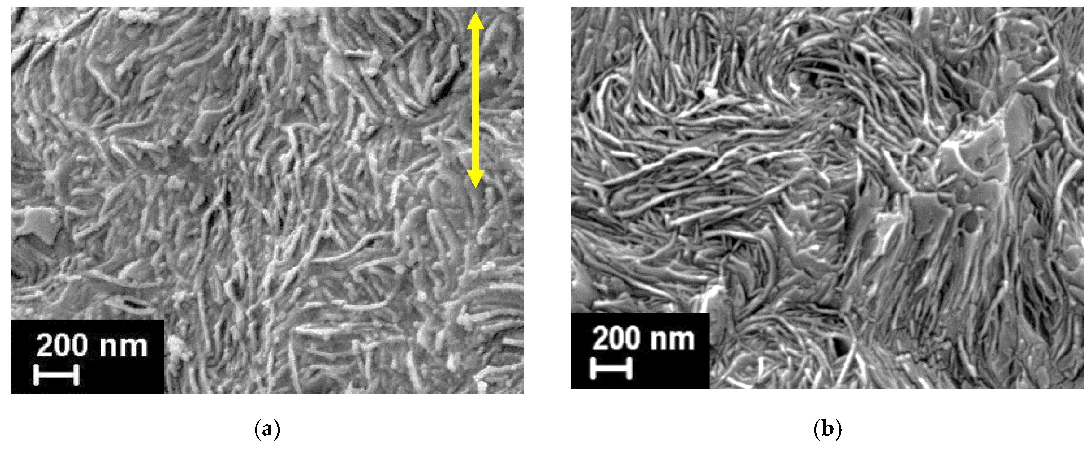
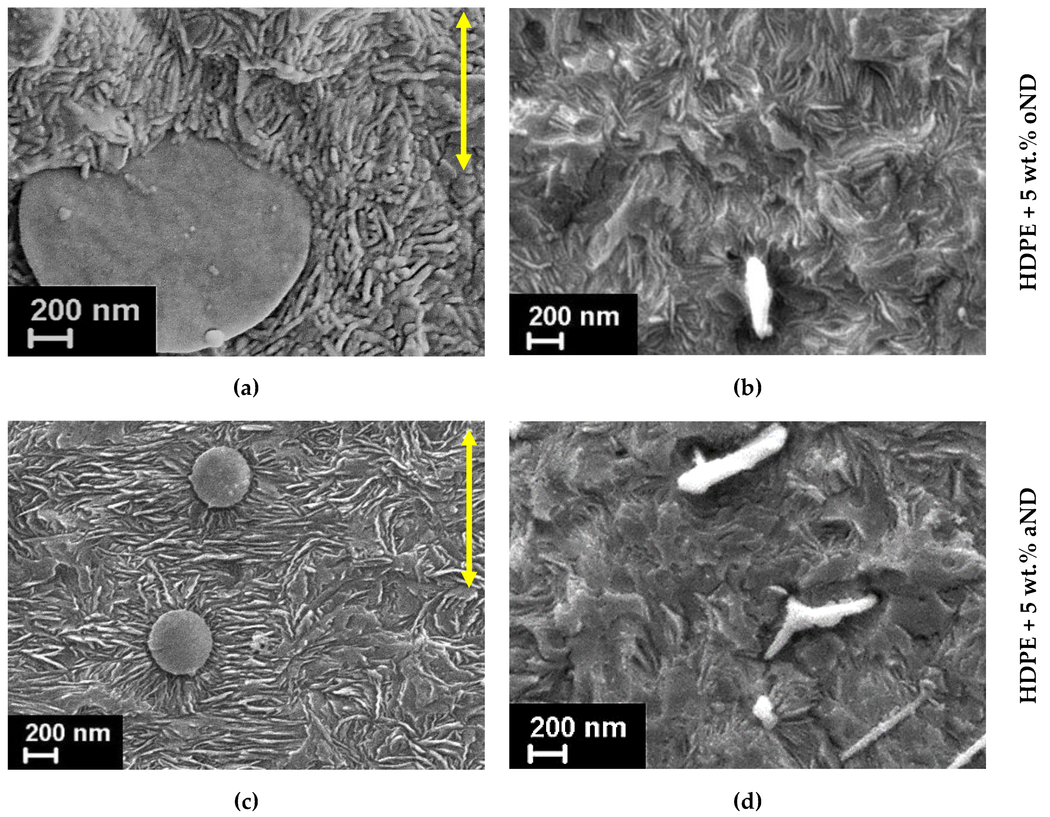
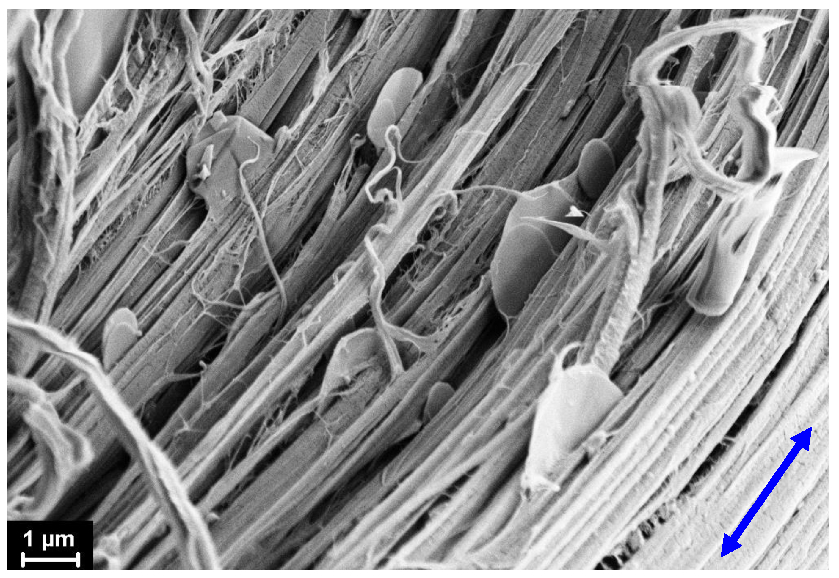
3.2. Scanning Electron Microscopy (SEM)
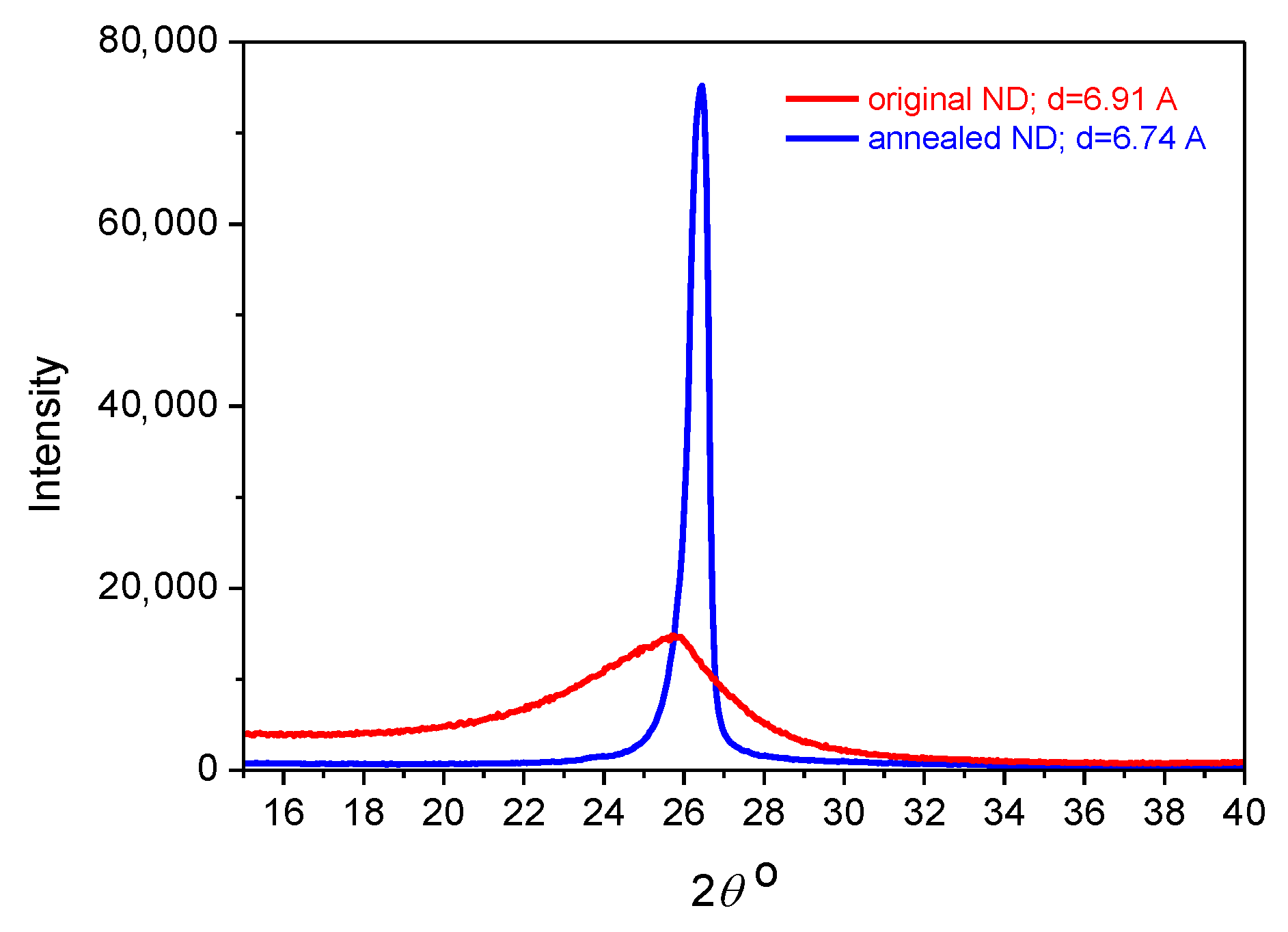
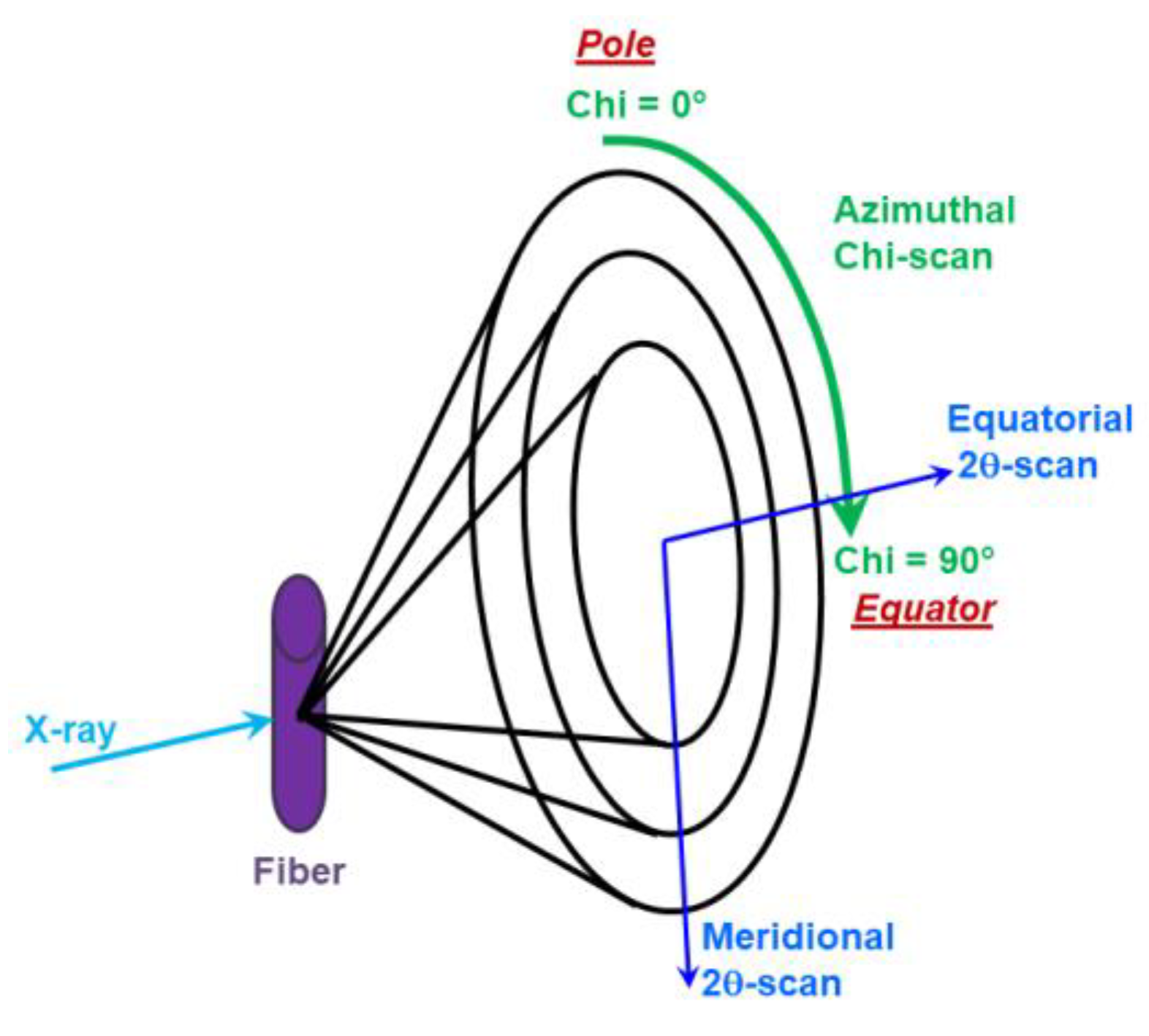
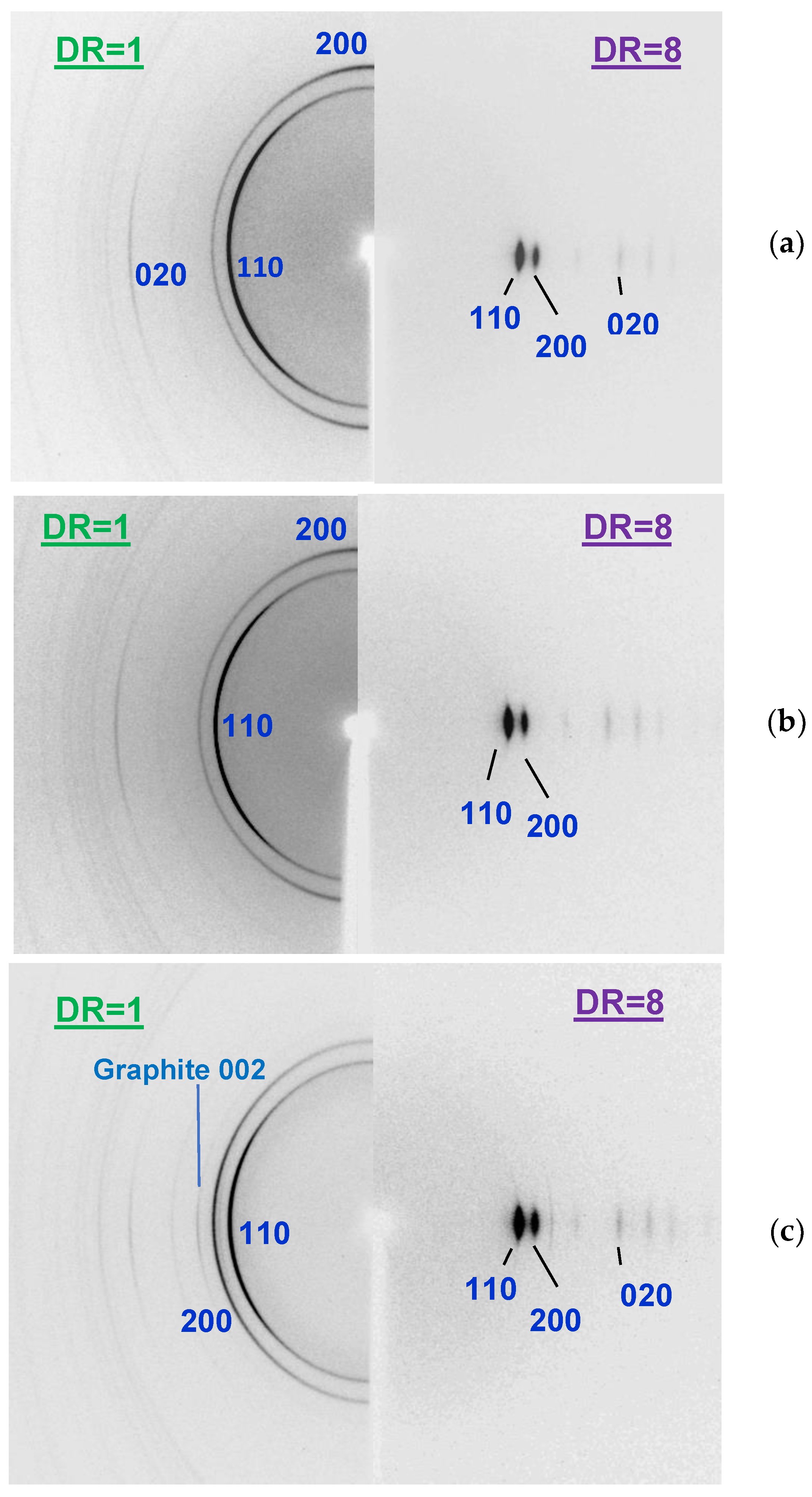
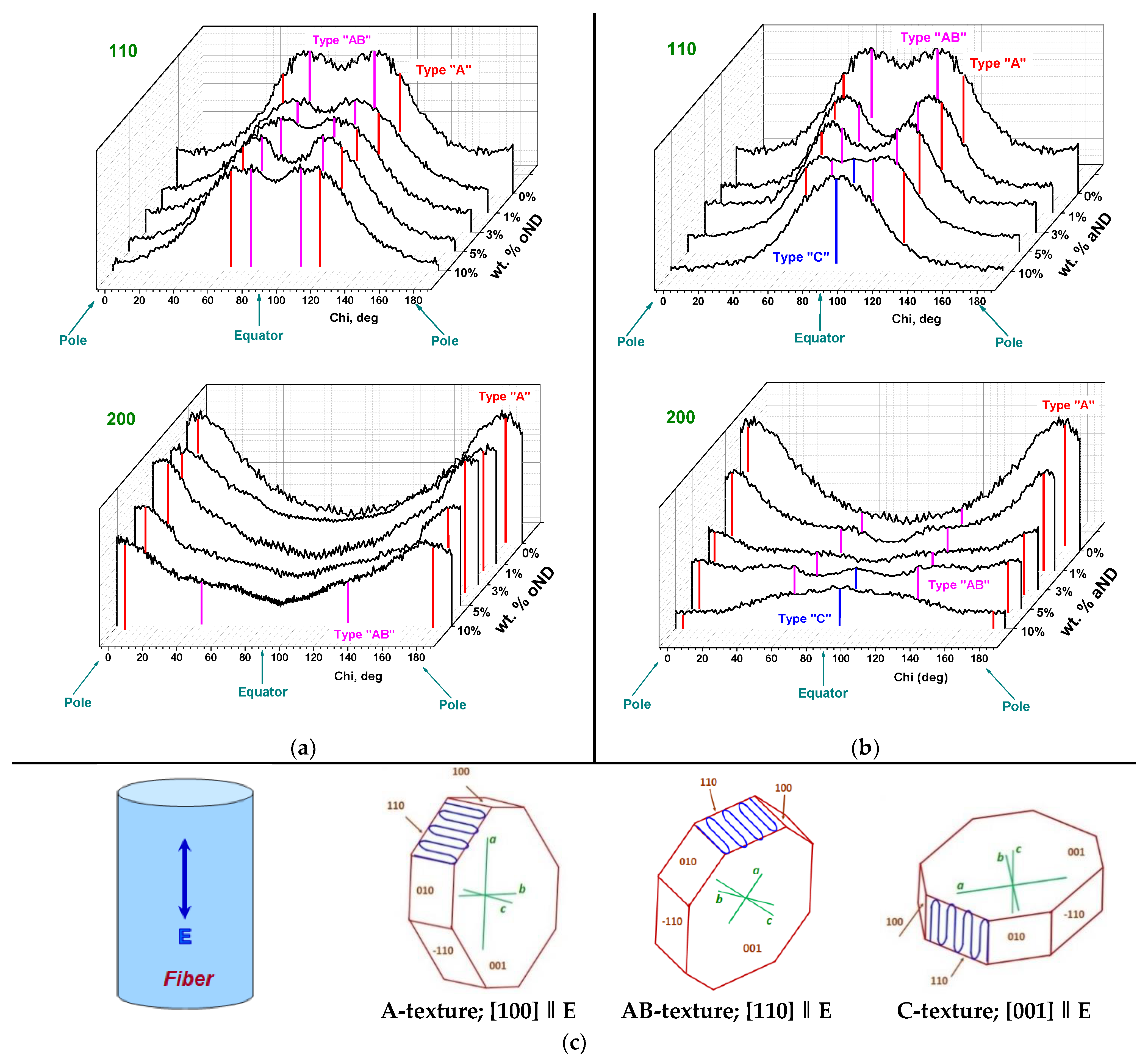
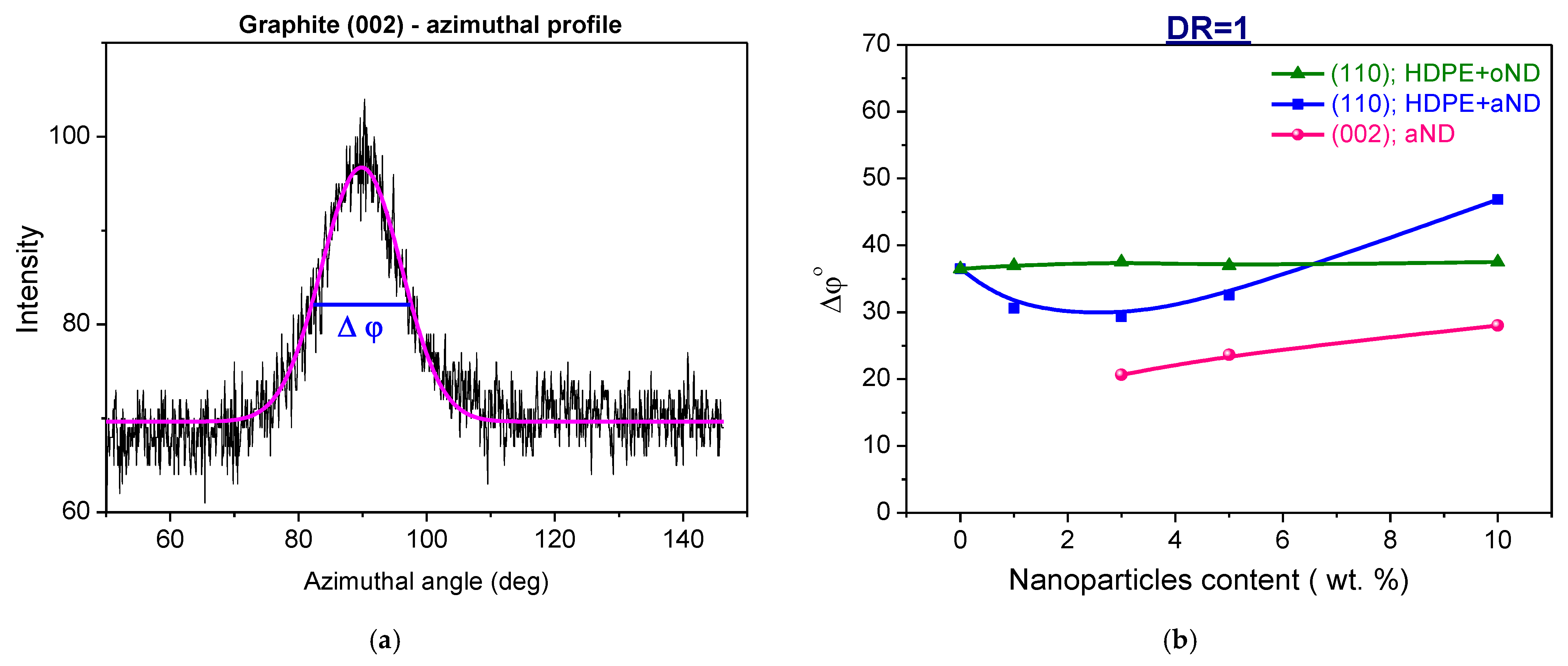
3.3. WAXS
4. Conclusions
Author Contributions
Funding
Institutional Review Board Statement
Informed Consent Statement
Data Availability Statement
Acknowledgments
Conflicts of Interest
References
- Higgins, T.D.; Bryant, G.M. Influence of melt spinning variables on the tensile properties of high density polyethylene fibers. J. Appl. Polym. Sci. 1964, 8, 2399–2425. [Google Scholar] [CrossRef]
- D’Amato, M.; Dorigato, A.; Fambri, L.; Pegoretti, A. High performance polyethylene nanocomposite fibers. Express Polym. Lett. 2012, 6, 954–964. [Google Scholar] [CrossRef] [Green Version]
- Fakirov, S. Oriented Polymer Materials; Huthig & Wepf: Basel, Switzerland, 1996; p. 512. [Google Scholar]
- Pennings, A.J.; Smook, J.; de Boer, J.; Gogolewski, S.; van Hutten, P.F. Process of preparation and properties of ultra-high strength polyethylene fibers. Pure Appl. Chem. 1983, 55, 777–798. [Google Scholar] [CrossRef]
- Holmes, D.R.; Miller, R.G.; Palmer, R.P.; Bunn, C.W. Crossed amorphous and crystalline chain orientation in polythene film. Nature 1953, 171, 1104–1106. [Google Scholar] [CrossRef]
- Keller, A. Unusual orientation phenomena in polyethylene interpreted in terms of the morphology. J. Polym. Sci. 1955, 15, 31–49. [Google Scholar] [CrossRef]
- Keller, A.; Machin, M.J. Oriented crystallization in polymers. J. Macromol. Sci. Part B 2006, 1, 41–91. [Google Scholar] [CrossRef]
- Keith, H.D.; Padden, F.J. The optical behavior of spherulites in crystalline polymers. Part I. Calculation of theoretical extinction patterns in spherulites with twisting crystalline orientation. J. Polym. Sci. 1959, 39, 101–122. [Google Scholar] [CrossRef]
- Hendus, H. Reihenstruktur und Röntgen-Kleinwinkelinterferenz von Polyäthylen. Kolloid-Z. Z. Polym. 1973, 251, 779–781. [Google Scholar] [CrossRef]
- Gerasimov, V.I.; Tsvankin, D.Y. X-ray study of extruded polyethylene films. Polym. Sci. USSR 1970, 12, 2944–2960. [Google Scholar] [CrossRef]
- Dees, J.R.; Spruiell, J.E. Structure development during melt spinning of linear polyethylene fibers. J. Appl. Polym. Sci. 1974, 18, 1053–1078. [Google Scholar] [CrossRef]
- Aggarwal, S.L.; Tilley, G.P.; Sweeting, O.J. Orientation in extruded polyethylene films. J. Appl. Polym. Sci. 1959, 1, 91–100. [Google Scholar] [CrossRef]
- Kobayashi, K.; Nagasawa, T. Crystallization of sheared polymer melts. J. Macromol. Sci. Part B Phys. 2006, 4, 331–345. [Google Scholar] [CrossRef]
- Lin, L.; Argon, A.S. Structure and plastic deformation of polyethylene. J. Mater. Sci. 1994, 29, 294–323. [Google Scholar] [CrossRef]
- Lindenmeyer, P.H.; Lustig, S. Crystallite orientation in extruded polyethylene film. J. Appl. Polym. Sci. 1965, 9, 227–240. [Google Scholar] [CrossRef]
- Peterlin, A. Molecular model of drawing polyethylene and polypropylene. J. Mater. Sci. 1971, 6, 490–508. [Google Scholar] [CrossRef]
- Mackley, M.R.; Keller, A. Flow induced crystallization of polyethylene melts. Polymer 1973, 14, 16–20. [Google Scholar] [CrossRef]
- Maxfield, J.; Mandelkern, L. Crystallinity, supermolecular structure, and thermodynamic properties of linear polyethylene fractions. Macromolecules 1977, 10, 1141–1153. [Google Scholar] [CrossRef]
- Stern, T.; Marom, G.; Wachtel, E. Origin, morphology and crystallography of transcrystallinity in polyethylene-based single-polymer composites. Compos. Part A Appl. Sci. Manuf. 1997, 28, 437–444. [Google Scholar] [CrossRef]
- Desper, C.R. Structure and properties of extruded polyethylene film. J. Appl. Polym. Sci. 1969, 13, 169–191. [Google Scholar] [CrossRef]
- Sekiguchi, Y.; Takarada, W.; Kikutani, T. Structure and properties of melt-spun fibers of polyethylene blended with cellulose fibers. AIP Conf. Proc. 2017, 1914, 130004. [Google Scholar]
- Farahbakhsh, N.; Roodposhti, P.S.; Ayoub, A.; Venditti, R.A.; Jur, J.S. Melt extrusion of polyethylene nanocomposites reinforced with nanofibrillated cellulose from cotton and wood sources. J. Appl. Polym. Sci. 2015, 132. [Google Scholar] [CrossRef]
- Fambri, L.; Dabrowska, I.; Pegoretti, A.; Ceccato, R. Melt spinning and drawing of polyethylene nanocomposite fibers with organically modified hydrotalcite. J. Appl. Polym. Sci. 2014, 131. [Google Scholar] [CrossRef] [Green Version]
- Gleeson, S.E.; Kim, S.; Yu, T.; Marcolongo, M.; Li, C.Y. Size-dependent soft epitaxial crystallization in the formation of blend nanofiber shish kebabs. Polymer 2020, 202, 122644. [Google Scholar] [CrossRef]
- Bin, Y.; Wang, H. Transcrystallization in polymer composites and nanocomposites. In Crystallization in Multiphase Polymer Systems; Elsevier: Amsterdam, The Netherlands, 2018; pp. 341–365. [Google Scholar]
- Ning, N.; Luo, F.; Wang, K.; Zhang, Q.; Chen, F.; Du, R.; An, C.; Pan, B.; Fu, Q. Molecular weight dependence of hybrid shish kebab structure in injection molded bar of polyethylene/inorganic whisker composites. J. Phys. Chem. B 2008, 112, 14140–14148. [Google Scholar] [CrossRef]
- Mai, F.; Wang, K.; Yao, M.; Deng, H.; Chen, F.; Fu, Q. Superior reinforcement in melt-spun polyethylene/multiwalled carbon nanotube fiber through formation of a shish-kebab structure. J. Phys. Chem. B 2010, 114, 10693–10702. [Google Scholar] [CrossRef]
- Sulong, A.B.; Park, J.H. Fabrication of Carbon Nanotubes Reinforced Polyethylene Fibers by Melt Spinning: Process Optimization and Mechanical Strength Characterization. Adv. Mater. Res. 2007, 26–28, 289–292. [Google Scholar]
- Sulong, A.B.; Park, J.; Azhari, C.H.; Jusoff, K. Process optimization of melt spinning and mechanical strength enhancement of functionalized multi-walled carbon nanotubes reinforcing polyethylene fibers. Compos. Part B Eng. 2011, 42, 11–17. [Google Scholar] [CrossRef]
- Slouf, M.; Synkova, H.; Baldrian, J.; Marek, A.; Kovarova, J.; Schmidt, P.; Dorschner, H.; Stephan, M.; Gohs, U. Structural changes of UHMWPE after e-beam irradiation and thermal treatment. J. Biomed. Mater. Res. Part B Appl. Biomater. 2008, 85, 240–251. [Google Scholar] [CrossRef]
- Bassett, D.C.; Olley, R.H. On the lamellar morphology of isotactic polypropylene spherulites. Polymer 1984, 25, 935–943. [Google Scholar] [CrossRef]
- Ivan’kova, E.; Kasatkin, I.; Moskalyuk, O.; Yudin, V.; Kenny, J.M. Structural aspects of mechanical properties of iPP-based composites. I. Composite iPP fibers with VGCF nanofiller. J. Appl. Polym. Sci. 2015, 132. [Google Scholar] [CrossRef]
- Marikhin, V.A.; Myasnikova, L.P.; Novak, I.I.; Suchkov, V.A.; Tukhvatullina, M.S. Molecular orientation in microfibrils and strength of oriented polyethylene. Polym. Sci. USSR 1972, 14, 2865–2870. [Google Scholar] [CrossRef]
- Marikhin, V.A.; Myasnikova, L.P.; Pel’tsbauer, Z. Formation of kink bands during orientation drawing of linear polyethylene. Polym. Sci. USSR 1981, 23, 2295–2304. [Google Scholar] [CrossRef]
- Gann, L.A.; Marikhin, V.A.; Myasnikova, L.P.; Budtov, V.P.; Myasnikov, G.D. Effect of temperature on the orientational drawing of polyethylenes of different molecular weight. Polym. Sci. USSR 1988, 30, 567–571. [Google Scholar] [CrossRef]
- Bershtein, V.A.; Yegorov, V.M.; Marikhin, V.A.; Myasnikova, L.P. Relationship between the melting cooperativity parameter, structure and strength of ultra-oriented polyethylene. Polym. Sci. USSR 1990, 32, 2500–2508. [Google Scholar] [CrossRef]
- Marikhin, V.A.; Myasnikova, L.P. Heterogeneity of structure and mechanical properties of polymers. Makromol. Chemie. Macromol. Symp. 1991, 41, 209–227. [Google Scholar] [CrossRef]
- Ivan’kova, E.; Vasilieva, V.; Myasnikova, L.; Marikhin, V.; Henning, S.; Michler, G.H. Comparison of structure formation upon drawing of gel-cast and melt-crystallised UHMWPE films. E-Polymers 2002, 2. [Google Scholar] [CrossRef] [Green Version]
- Sui, G.; Zhong, W.H.; Ren, X.; Wang, X.Q.; Yang, X.P. Structure, mechanical properties and friction behavior of UHMWPE/HDPE/carbon nanofibers. Mater. Chem. Phys. 2009, 115, 404–412. [Google Scholar] [CrossRef]
- Katayama, K.; Nakamura, K.; Amano, T. Structural formation during melt spinning process. Kolloid-Z. Z. Polym. 1968, 226, 125–134. [Google Scholar] [CrossRef]
- Haggenmueller, R.; Fischer, J.E.; Winey, K.I. Single wall carbon nanotube/polyethylene nanocomposites: Nucleating and templating polyethylene crystallites. Macromolecules 2006, 39, 2964–2971. [Google Scholar] [CrossRef] [Green Version]


Publisher’s Note: MDPI stays neutral with regard to jurisdictional claims in published maps and institutional affiliations. |
© 2022 by the authors. Licensee MDPI, Basel, Switzerland. This article is an open access article distributed under the terms and conditions of the Creative Commons Attribution (CC BY) license (https://creativecommons.org/licenses/by/4.0/).
Share and Cite
Ivan’kova, E.; Kasatkin, I.; Vaganov, G.; Elokhovskiy, V.; Bugrov, A.; Yudin, V.; Pavlova, E.; Slouf, M. Morphological Transformation in Polymer Composite Materials Filled with Carbon Nanoparticles: Part 1—SEM and XRD Investigations. Materials 2022, 15, 3531. https://doi.org/10.3390/ma15103531
Ivan’kova E, Kasatkin I, Vaganov G, Elokhovskiy V, Bugrov A, Yudin V, Pavlova E, Slouf M. Morphological Transformation in Polymer Composite Materials Filled with Carbon Nanoparticles: Part 1—SEM and XRD Investigations. Materials. 2022; 15(10):3531. https://doi.org/10.3390/ma15103531
Chicago/Turabian StyleIvan’kova, Elena, Igor Kasatkin, Gleb Vaganov, Vladimir Elokhovskiy, Alexander Bugrov, Vladimir Yudin, Ewa Pavlova, and Miroslav Slouf. 2022. "Morphological Transformation in Polymer Composite Materials Filled with Carbon Nanoparticles: Part 1—SEM and XRD Investigations" Materials 15, no. 10: 3531. https://doi.org/10.3390/ma15103531