1. Introduction
Thermally sprayed ceramic coatings are widely used in industry to provide mechanical, chemical and thermal protection. Coatings are prepared by introducing the feedstock material, most often in a form of powder, into a hot plasma jet, where it is melted and propelled towards a prepared substrate. After their impact at the substrate, the molten particles flatten and solidify in a form of disk-like platelets called splats. Plasma spraying inherently possesses extremely high cooling rates of the particles, in the range 10
3–10
6 K/s, thereby frequently giving rise to a formation of non-equilibrium phases, microstructures of fine columnar grains [
1] or even amorphous phases [
2].
Due to its low price as well as good chemical and wear resistance, Al
2O
3 is often used as a material of the first choice for protecting metallic parts from wear and corrosion. Additionally, Al
2O
3 properties can be further significantly improved when it is mixed with other components. For example, Al
2O
3−Y
2O
3 and Al
2O
3−TiO
2 composite coatings possess higher wear resistance than pure Al
2O
3 [
3,
4], while the addition of ZrO
2 increases the coatings’ toughness [
5].
Another way to improve the coating properties is a preparation of nanocrystalline or sub-micron microstructure: nanocrystalline materials are characterized by a microstructural length or grain size of up to about 100 nm, while microstructure having grain sizes from ∼0.1 to 0.3 μm are classified as submicron materials [
6]. It was shown that nanocrystalline materials possess better mechanical properties than their coarse-grained counterparts [
7]. For instance, a nanocrystalline Inconel 718 coating deposited by high velocity oxygen fuel (HVOF) method exhibited a significant increase in hardness (by approximately 60%) over that of the Inconel 718 control sample [
8]. Another results published in [
9] showed that decreasing the grain size of Al
2O
3 feedstock powder from ∼50 μm down to 300 nm increased the tensile adhesion strength of the deposited coating by a factor of three and the coating wear resistance was increased by a factor of ten. Nanostructured zirconia coatings deposited by plasma spraying in the study by Chen et al. [
10] showed that the wear rates of the nanostructured coatings were about 40% of those of traditional zirconia coatings under loads from 20 to 80 N. Owing to these outstanding performances, targeted applications have been successfully implemented for hard and wear-resistant ceramic coatings in industrial sectors in the past decade [
6].
Suspension plasma spraying has been intensively studied as a reliable method of preparation of coatings with such fine, nanometric-grain microstructure. In the early suspension experiments, nano-sized particles were used. However, their tendency towards agglomeration as well as associated difficult handling and potential health risk of using such suspensions [
11] triggered a shift to using sub-micrometric particles instead. Even though the coatings prepared by suspension plasma spraying route can often surpass the coatings prepared from dry powders [
9], their industrial application remain rather scarce at the moment, owing to difficulties in the coating preparation and relatively low deposition rate (coating thickness increase per torch pass) compared to dry powder plasma spraying [
12,
13].
An alternative approach to preparation of nanocrystalline coatings is based on deposition of amorphous coatings from coarse powders and their subsequent heat treatment in order to induce growth of nanocrystalline grains in the microstructure. Deposition of such amorphous microstructures can be relatively easily implemented through the rapid solidification of the particles in plasma spraying, provided the cooling rates are sufficiently high to fully suppress crystalline growth. It has been previously reported that materials with near-eutectic composition can solidify as fully or partially amorphous solids, and this finding was widely used for preparation of e.g. metallic glasses [
14] or amorphous ceramics, such as Al
2O
3−Y
2O
3, Al
2O
3–ZrO
2 and Al
2O
3–ZrO
2–SiO
2 systems, as presented in [
3,
15,
16,
17,
18,
19]. Transformation of amorphous coating of the ternary Al
2O
3–ZrO
2–SiO
2 system into nanocrystalline coating was successfully reported in our previous studies [
19,
20], where an improvement of the mechanical properties was also described. In both studies, amorphous atmospheric plasma sprayed materials Al
2O
3–ZrO
2 and Al
2O
3–ZrO
2–SiO
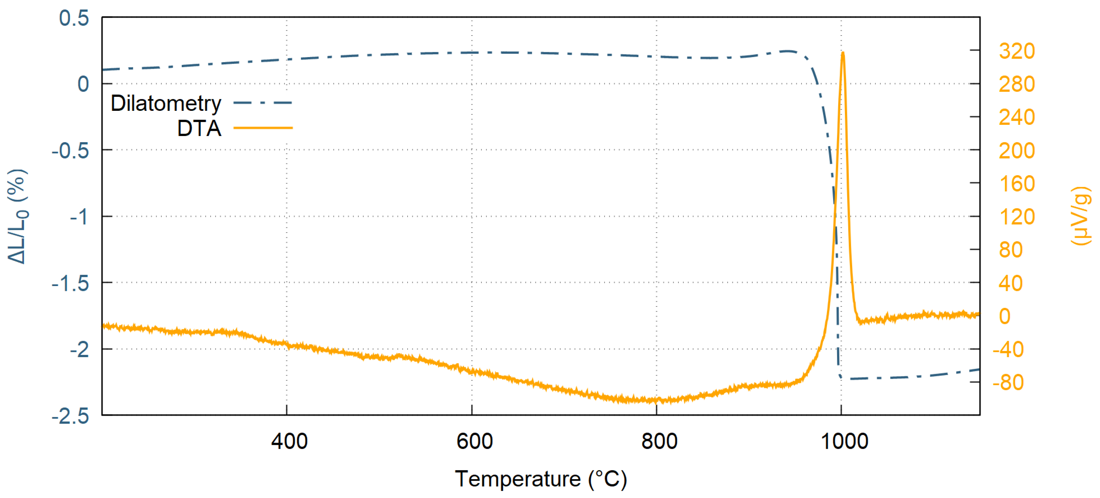
2 were isothermally heat treated at various temperatures above the crystallization temperature (980 °C), forming nanocrystallites embedded in the amorphous matrix. Size of the nanocrystallites was strongly dependent on the heat treatment temperature and resulted in different mechanical properties, such as hardness and flexural strength [
20].
The traditional way of heat treatment of amorphous materials would be furnace treatment; however, it is not applicable for coatings on metallic substrates because of substrate oxidation, grain growth and even possible spallation of the coating, caused by the differences in the substrate–coating coefficients of thermal expansion. In this paper, we present two alternative methods of heat treatment of amorphous Al2O3−ZrO2−SiO2 coatings deposited by atmospheric hybrid water stabilized plasma torch (WSP-H). The study is focused on laser and plasma surface heat treatment techniques, i.e., industrially relevant methods with high potential. As opposed to furnace annealing (used as a reference method for free standing ceramic parts), both of these methods enable on-site modification of the coating properties without inducing any detrimental changes to the metallic substrate material and enable surface heat treatment of large-sized components, such as paper-mill rollers. Upon the treatment, the phase composition and microstructure changes were evaluated by XRD and SEM, respectively, and the associated mechanical response of the coating to heat treatment was studied by measuring the Vickers microhardness and Pin on Disc wear resistance tests.
2. Materials and Methods
Feedstock Al
2O
3−ZrO
2−SiO
2 ceramic powder was obtained by crushing commercially available bulk material Eucor (Eutit Ltd., Stara Voda, Czech Republic). The powder was sieved into a sprayable size distribution with
D50 = 89 μm, as measured by particle size analyser Mastersizer 3000 (Malvern, UK). Using the EDX analysis, the near eutectic composition of the feedstock powder was determined as 49% Al
2O
3, 31% ZrO
2 and 19% SiO
2 (all ± 2%). The hybrid water stabilized plasma torch WSP-H 500 (ProjectSoft, Hradec Kralove, Czech Republic) was used for plasma spraying onto S235 steel substrates with dimensions 50 × 30 × 10 mm
3. The torch was operated at 500 A (∼150 kW) and 15 slpm argon flow rate. In addition to argon, the torch consumes about 20 g/min of demineralized water, which is evaporated and ionized to supply the plasma with hydrogen and oxygen ions (for detailed information about spraying with the WSP-H torch, refer to [
21,
22]). The stand-off distance was set to 350 mm and powder was injected radially into plasma jet at a feeding distance (i.e., the distance of the powder injection point from the torch exit nozzle) of 35 mm and powder feed rate of 10 kg/h (167 g/min).
Prior to the deposition, the substrates were grit blasted by alumina grit (Ra = 8.1 ± 0.3 μm) and mounted to a revolving carousel. The substrates temperature during the deposition was measured by infra-red camera TIM160 (Micro-Epsilon, Ortenburg, Germany) facing the substrates’ front side, as well as by a K-type thermocouple inserted into a hole drilled from the back-side of one of the samples and reaching 1 mm under the coated surface. The substrates were preheated by 3 cycles of plasma torch with deactivated powder feeding. To prepare a coating with a 1.5 mm thickness, 11 successive plasma torch cycles were needed. One deposition cycle consisted of three up and down strokes and was followed by an extensive cooling. Each deposition cycle was manually triggered when temperature measured by the thermocouple dropped to 250 °C.
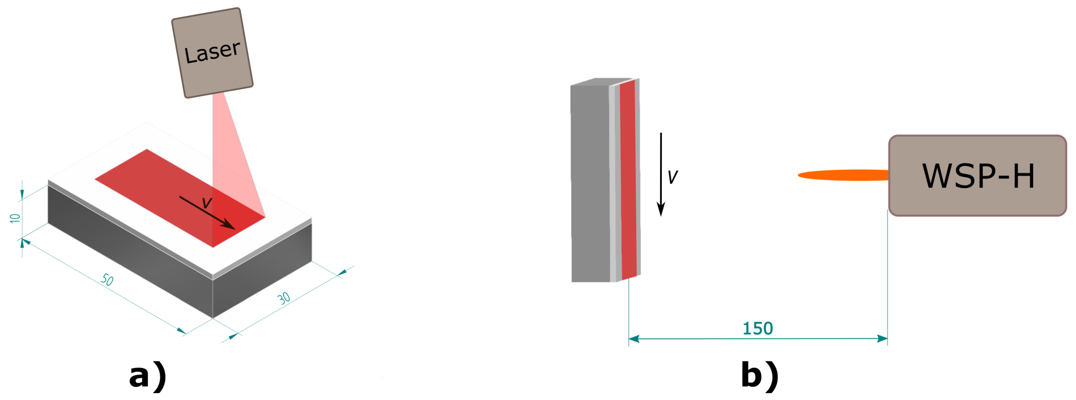
To facilitate an accurate determination of the heat treatment variants’ influence, the as-sprayed coatings were polished down using a P600 diamond disc. Subsequently, the samples were subjected to one of two methods of surface heat-treatment: laser or plasma. The laser treatment was performed using a high power diode laser (Laserline GmbH, Muhlheim-Karlich, Germany) with maximal output power of 9 kW,
= 915–1030 nm, 1000 μm fibre diameter, 400 mm focal length and laser focus diameter 7.5 mm. The laser transverse velocity and power were varied to obtain 15 different laser heat-treatment conditions in total. On the other hand, high enthalpy plasma generated heat produced by the plasma torch offers a quick and readily available alternative since the heat treatment can be performed directly after the coating deposition using the same plasma torch that was used for the coating deposition. The torch transverse velocity and power were modified, in order to prepare 6 different plasma heat-treatment conditions. The samples were mounted into a stationary sample holder and heat-treated by a single pass of the plasma torch at a stand-off distance of 150 mm. A schematic illustration of the two surface heat-treatment methods is provided in
Figure 1.
Stripped-off ceramic coatings were then also prepared from the as-sprayed samples by grinding off the substrates. These coatings were used for measurement of the thermal expansion using vertical dilatometer Setsys 16/18 (Setaram, Caluire-et-Cuire, France) and to determine the crystallization onset temperatures using a Bahr STA 504 differential thermal analyser (Bahr, Hullhorst, Germany). In addition to the two surface heat-treatment methods, complimentary furnace annealing of the stripped-off ceramic samples was carried out. The furnace Entech EEF 5/16-HV (Entech, Angelholm, Sweden) was first preheated to the temperature 1050 °C and the samples were then inserted for a specified time. Such samples, isothermally treated in the whole volume (as opposed to gradient heating during laser or plasma treatment), were used as a reference set.
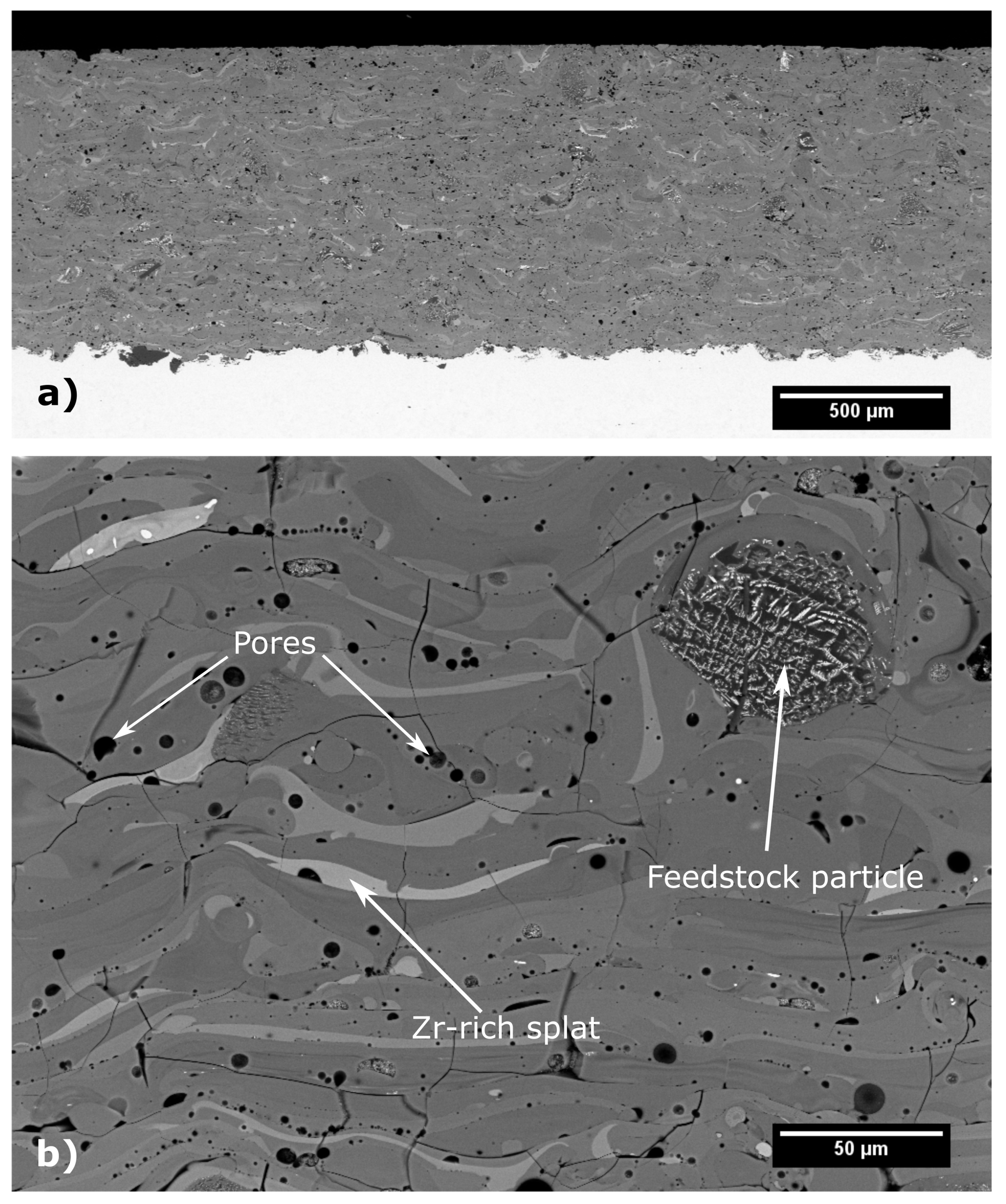
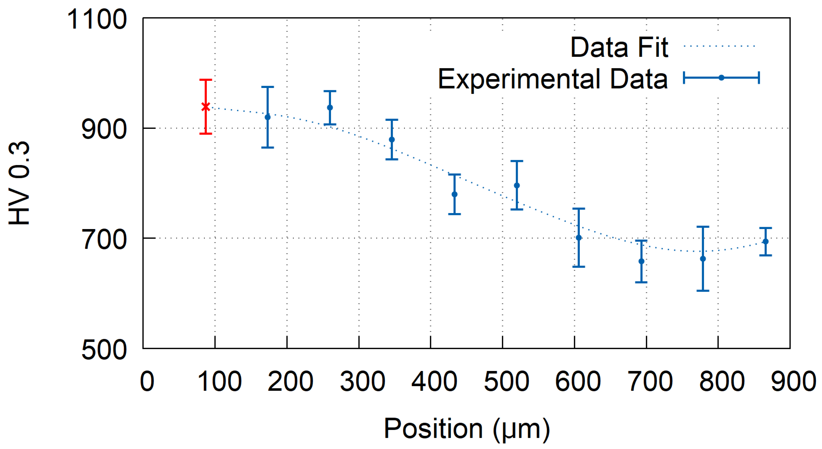
Metallographic samples of all specimens were prepared using Tegramin-25 automated polishing system (Struers, Willich, Denmark). The polished cross-sections were observed using a scanning electron microscope EVO MA 15 (Carl Zeiss SMT, Oberkochen, Germany) equipped with XFlash 5010 energy-dispersive spectrometer EDX (Bruker, Hamburg, Germany). Porosity of the coating was evaluated from seven SEM micrographs with nominal magnification 500× using semi-automatic thresholding procedure in ImageJ software (National Institutes of Health, Bethesda, MD, USA). Vickers microhardness profiles were measured on the polished sample cross-sections throughout the coating thickness using Q10A+ universal hardness tester (Qness, Golling an der Salzach, Austria), using the load of 300 g and dwell time 10 s. The average value of Vickers microhardness was calculated from at least 5 indents. Phase composition was evaluated on the free surfaces of the samples by powder X-ray diffractometer (XRD) D8 Discover (Bruker, Hamburg, Germany), using Cu anode and equipped with 1D detector. The degree of crystallinity, size of coherently diffracting domains (CDD) and microstrains were evaluated by quantitative Rietveld analysis of the acquired XRD spectra. Broadening of the diffraction peaks and background fitting were analysed using TOPAS V5 software (Bruker AXS, Hamburg, Germany). It was assumed that the effects of small crystallite size and microstrains contribute to broadening of Lorentzian and Gaussian components of pseudo-Voigt function, respectively [
23].
Tribological properties were measured by CSEM High Temperature Tribometer (Anton Paar GmbH, Graz, Austria) by dry sliding Pin on Disc test according to ASTM G99 05 standard. The tests were carried out at room temperature, in air atmosphere (31% relative humidity) without lubrication using alumina counterpart ball (6 mm diameter) with 10 N normal load, 0.1 m·s−1 speed and measured distance of 110 m in 5000 cycles (track radius 3.5 mm). The wear tracks profiles were measured by profilometer P-6 Profiler (KLA-Tencor, Milpitas, CA, USA), at four different places, and the wear volume was calculated.
4. Discussion
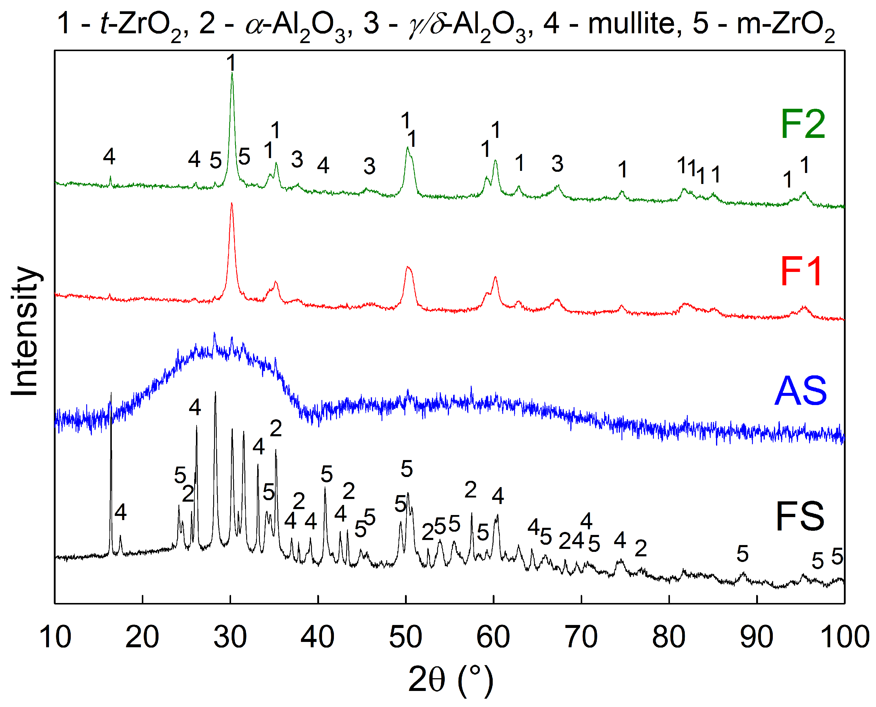
The original crystalline feedstock powder was transformed during spraying to almost fully amorphous coatings, as can be seen from the diffraction patterns in
Figure 9 and
Table 2, where FS and AS stand for feedstock powder and as-sprayed coating, respectively. Subsequently, the amorphous phase was partially transformed back to crystalline during heat treatment, forming mainly t-ZrO
2 nano-crystals, together with
-Al
2O
3 and m-ZrO
2. Silicon dioxide, present in the original feedstock, remained in the amorphous phase, or transformed to mullite (3Al
2O
3·2SiO
2), depending on the heat treatment conditions of the samples.
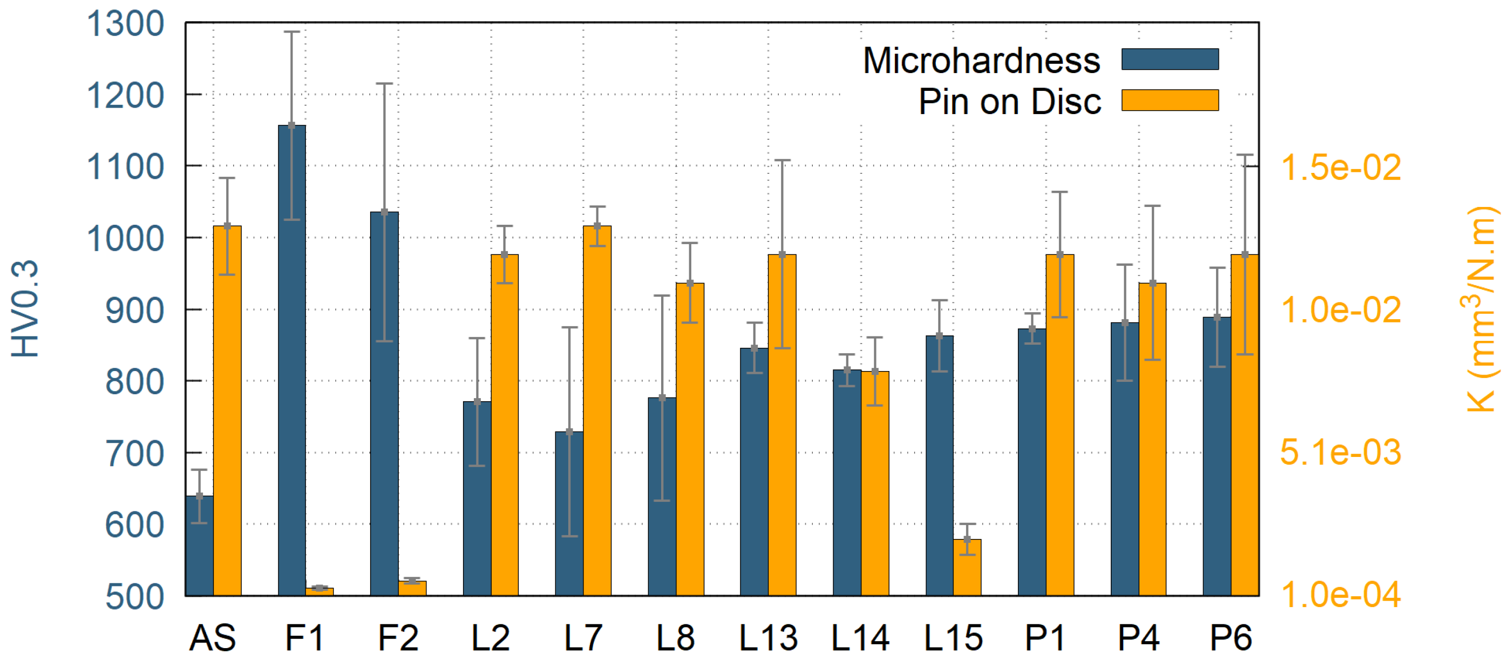
The furnace heat treatment resulted in almost fully crystalline samples (87% and 100% crystallinity for samples F1 and F2, respectively). As expected, both of these samples showed the highest Vickers microhardness values 1156 ± 131 HV0.3 for sample F1 and 1035 ± 180 HV0.3 for sample F2, as well as the best wear resistant behaviour with material volume loss of 2.9 × 10
−4 mm
3/N·m for sample F1 and 5.4 × 10
−4 mm
3/N·m for sample F2 (see
Table 1 for wear rate results of all samples). This was due to the fact that, during the crystallization, the coatings could freely undergo unconstrained shrinkage, since they were removed from the substrate prior the heat treatment. Consequently, there was no CTE mismatch between the substrate and the coating, resulting in no additional cracking. Furthermore, some micro-cracks originally present in the as-sprayed material closed up by the sintering effect during the heat treatment, which improved the mechanical properties as well. However, the highest contribution to the observed increase in microhardness and wear-rate resistance may be attributed to formation of nanocrystallites of various phases within the microstructure. In particular, a formation of t-ZrO
2 is believed to have a significant influence on the improvement of mechanical properties. In order to conceive fine differences in the microstructure, crystallite size (or coherently diffracting domains’ size) of the t-ZrO
2 phase was determined by the Rietveld refinement method for XRD diffractograms (see
Table 2). Crystallite size of the t-ZrO
2 phase of the sample F1 showed the smallest crystallite size (14 nm) from all the measured samples.
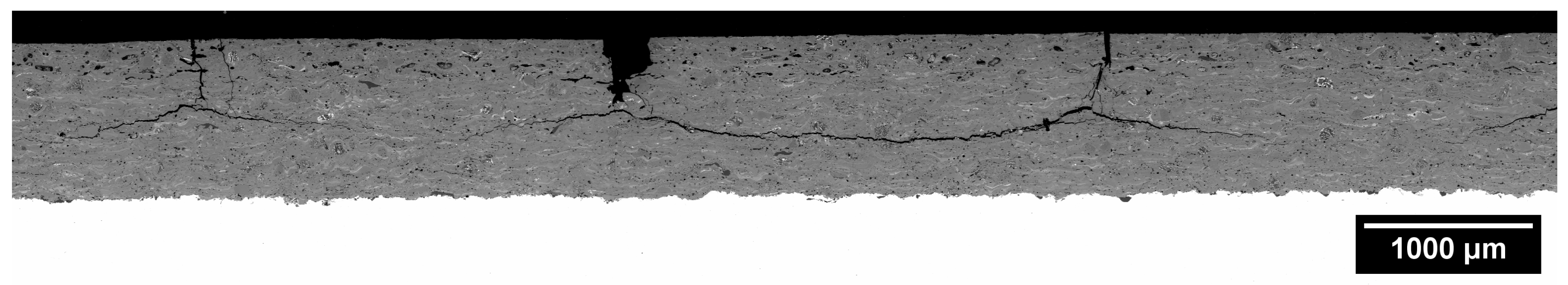
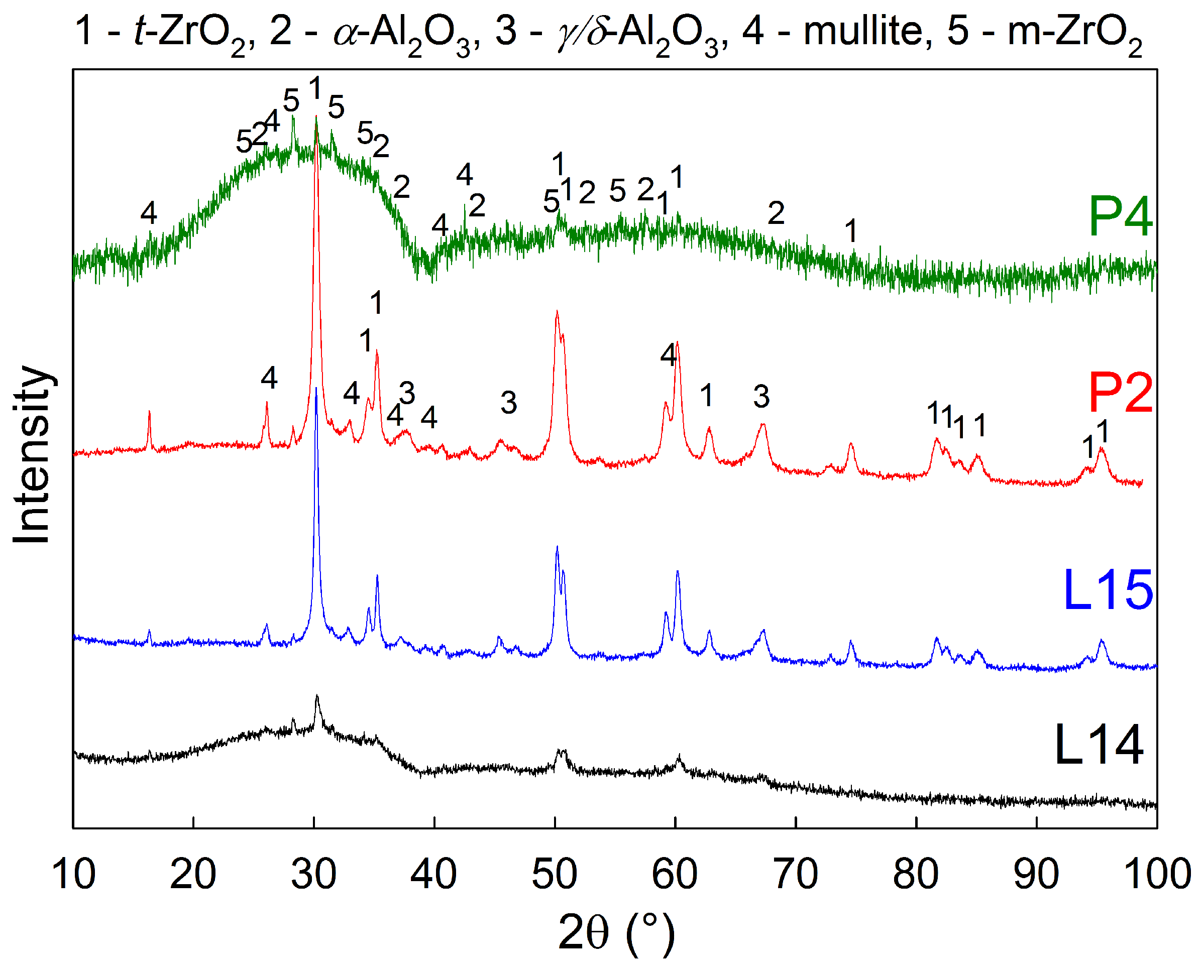
Laser heat treated samples showed significant formation of vertical cracks, originating from the constrained shrinkage during the crystallization. Therefore, samples with no cracks or short vertical cracks only were selected for further tests, since extensive cracking of the samples may compromise its overall mechanical properties, corrosion and chemical resistance. The best mechanical properties were measured for the samples L14 and L15, which exhibited rather low wear rates of 7.9 × 10
−3 mm
3/N·m and 2.0 × 10
−3 mm
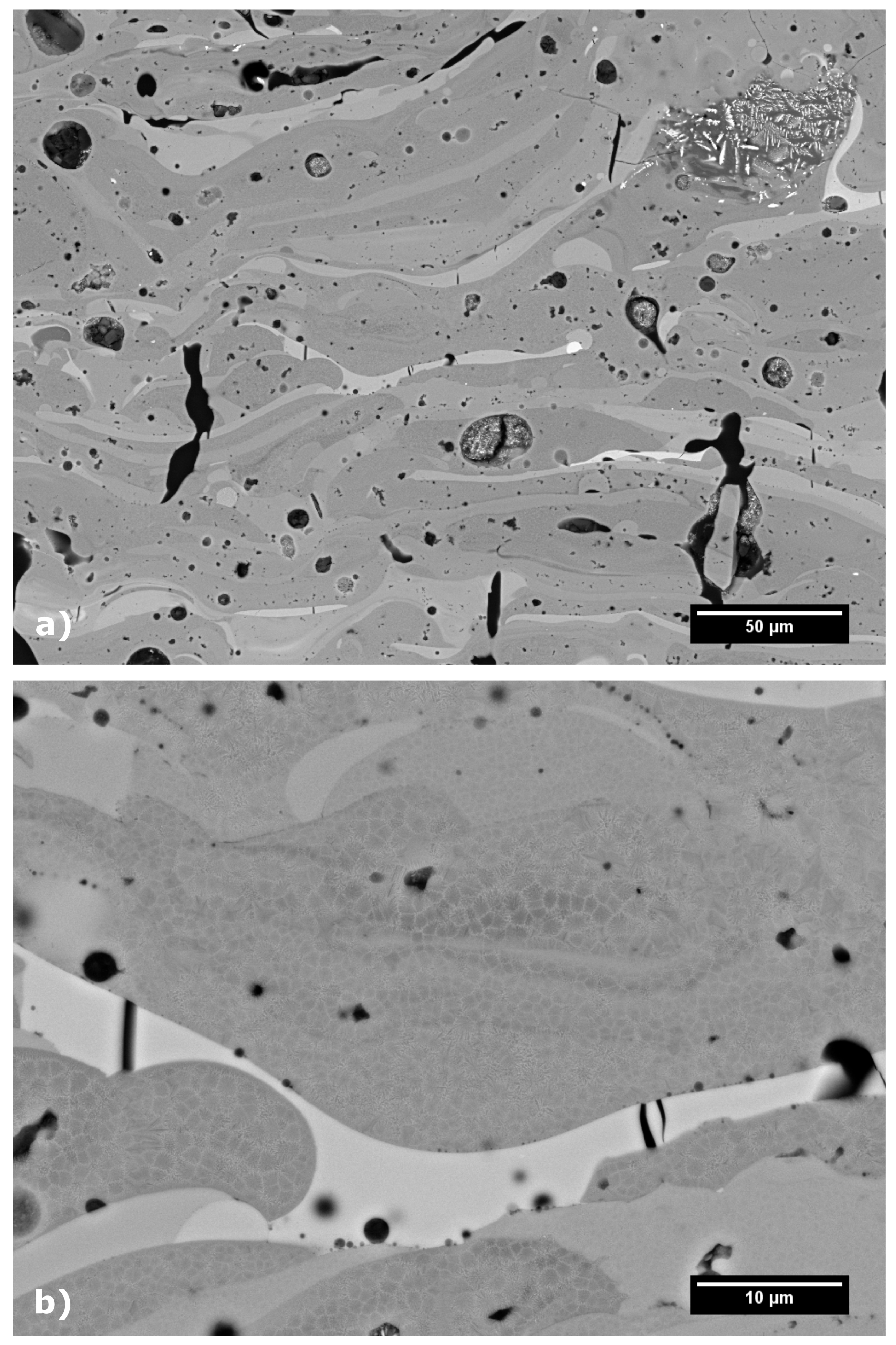
3/N·m, respectively. For these samples, the highest transverse velocity of the laser of 800 mm/min was used, combined with the highest laser powers of 1100 W and 1300 W, respectively. These two samples showed only limited cracking, significant increase in Vickers microhardness up to 863 ± 50 HV0.3 for sample L15 and improvement in wear resistant properties (compared to the as-sprayed coating). In fact, the sample L15 showed the best wear resistance from all surface heat treated samples. Similarly to the furnace treated samples, the sample L15 transformed to fully crystalline material, in the vicinity of the coatings surface, with the average CDD of t-ZrO
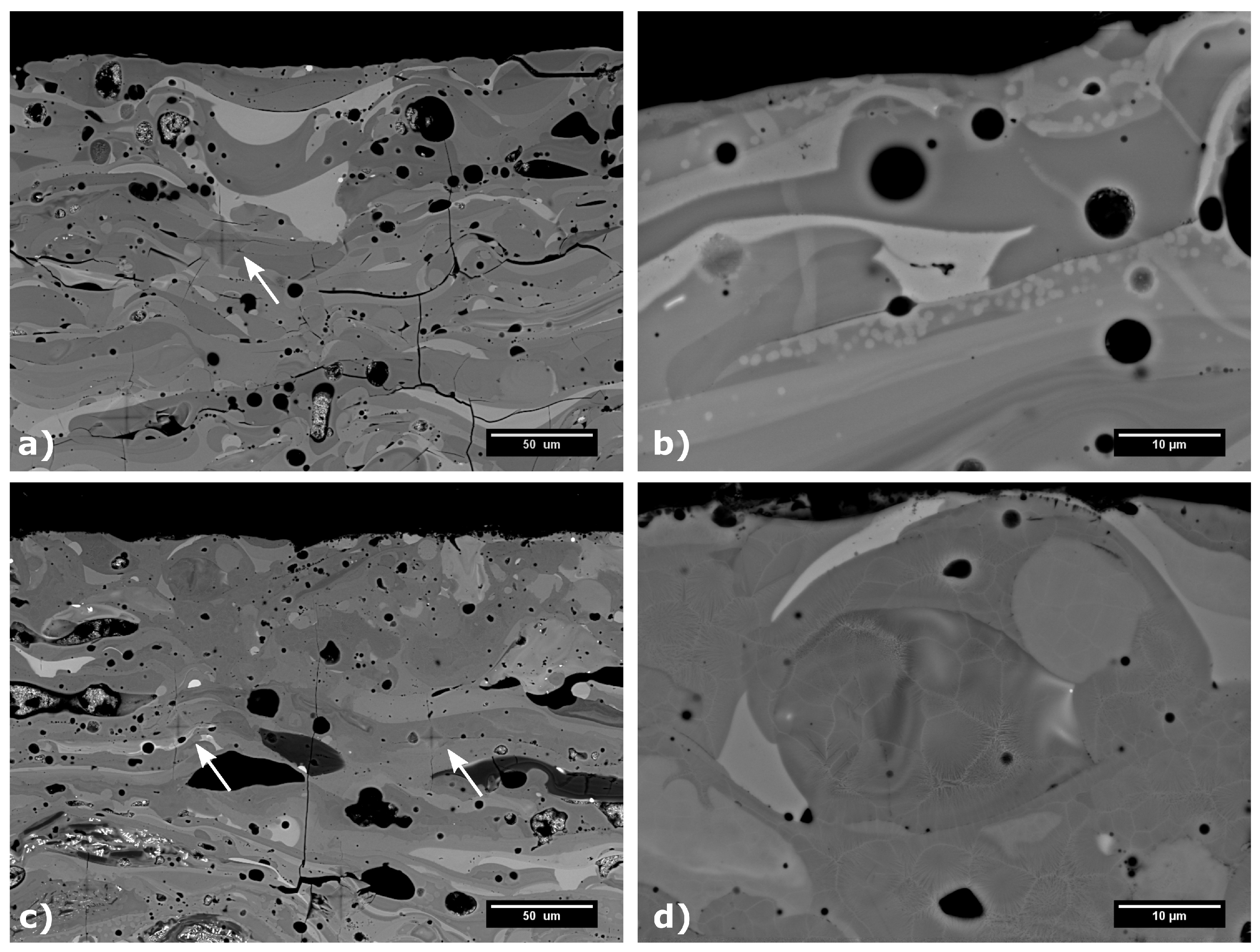
2 of 32 nm. The change in the microstructure and the appearance of Vickers indents are presented in
Figure 10a,b. From
Figure 10, formation of bright domains within individual splats was observed in sample L15. These may be segregated domains of ZrO
2 phase; however, they are too small for an accurate identification by EDX. Interestingly, the sample L14 remained mostly amorphous, with only 17% of the sample surface crystallized, as evaluated by the Rietveld analysis of XRD patterns measured from the sample surface. The rather incomplete crystallization was caused by the fact that the combination of 800 mm/min transverse velocity and lower power of 1100 W heated up the sample’s surface just a little above the crystallization temperature. Due to cooling through substrate heat transfer, the crystallization was very limited in this case, which in turn leads to inferior wear resistance, in comparison with the sample L15.
Plasma heat treatment resulted in an increase of the Vickers microhardness for the samples P1, P2, P4 and P6. Surprisingly, the related improvement of wear resistance of plasma heat treated samples was not so pronounced, compared to the as-sprayed sample. This was probably caused by the used high transverse velocity selected to prevent melting of the samples’ surfaces. The high plasma torch movement speeds resulted in very short time of treatment, during which the samples were exposed to the temperatures above the crystallization point. Consequently, the grain nucleation and diffusion growth processes were limited and possibly happened only on the very specimen surface. The XRD patterns of all but one of the plasma treated samples showed only minor changes, compared to the as-sprayed samples. The only difference was the sample P2, which was produced using the highest plasma power of 150 kW and lowest transverse velocity of 3000 mm/min and its XRD pattern suggest 100% surface crystallinity, comparable to the laser treated sample L15 (see the
Figure 11). However, the wear resistance properties were not measured for the P2 sample, since the most excessive cracking was observed in the SEM (see the
Figure 6). In between the cracks, the cross-section of the sample P2 showed a microstructure (
Figure 10) similar to the one of furnace treated samples F1 and F2. Formation of dark domains of alumina, enclosed by lighter regions, rich in ZrO
2 were observed in back scattered electron mode in SEM and such element distribution was confirmed by local EDX analysis. The remaining plasma heat treated samples didn’t show any changes in the phase composition (compared to the as-sprayed state) and, therefore, no microstructure changes were observed in SEM for them.
Plasma surface heat treatment of the ceramic coating is very challenging. The power density of high enthalpy plasma torch, combined with low thermal conductivity of the ceramic coatings needs precise adjustment of heat treating conditions to provide sufficient heat treatment of the coating and, at the same time, prevent the coating from undesirable overheating (or even remelting). Therefore, further optimization of plasma heat treatment conditions, e.g., a change in the stand-off distance, or the use of multiple short passes of the plasma torch above the coating, has the potential to result in similar improvement of mechanical properties, such as was presented for the samples heat treated by laser. The analysis of the wear tracks in the SEM showed remarkable differences in the wear mechanism. The as-sprayed sample displayed rather wide (over 3 mm) wear track, reflecting its high material removal rate in the Pin on Disc test. The observed wear mechanism was mainly debonding and cracking of loosely connected splats which were crushed by the sliding ball, leaving coarse debris in the wear track. On the other hand, the furnace-treated samples showed shallow and narrow wear track (about 1.1 mm in width) filled with fine debris originating mainly from grinding off of the sintered splats. No splat debonding was observed for the furnace-treated sample. A combination of both above-mentioned mechanisms was observed for laser and plasma treated samples, where the wear tracks were filled with mixture of fine and coarse wear debris, the former originating from grinding off of the surface, and the latter formed due to debonding and cracking of splats.
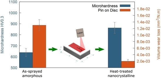
5. Conclusions
Ceramic powder of near eutectic composition from the ternary system of Al2O3−ZrO2−SiO2 was plasma sprayed onto steel substrates to create 1 mm-thick coatings. Atmospheric plasma spraying was carried out by hybrid water stabilized plasma torch WSP-H 500. The as-sprayed coatings were amorphous and their hardness and wear resistance are rather low. Unfortunately, bulk furnace treatment is not applicable for coatings on metallic substrates, since it irreversibly deteriorates the properties of the substrate and causes cracking and spallation of the coating due to CTE mismatch and substrate oxidation. Therefore, the coatings were subjected to surface heat-treatment to improve mechanical properties of the coating while maintaining good adhesion to the substrate. In addition, the stripped-off coatings were subject to furnace heat treatment to obtain reference samples. The surface heat treatment by laser or plasma torch resulted in significant changes in the coating microstructure. The surface layer of the coating transformed from amorphous to nanocrystalline structure within the splats. Some of the heat treatment conditions led to formation of vertical cracks in the coatings, which compromised their overall mechanical properties. In other cases, these changes were accompanied by improvement of the coating mechanical properties. Vickers microhardness increased from 639 ± 37 HV0.3 for the as-sprayed coating, up to 1156 ± 131 and 1129 ± 169 HV0.3 for the furnace treated and selected plasma treated samples, respectively. Wear resistance was improved more than six times, from the value of material volume loss 1.3 × 10⁻² mm3/N·m of the as-sprayed sample, down to 2.0 × 10⁻³ mm3/N·m for some laser treated samples. The changes in mechanical properties of the heat treated samples were caused by the solid stage crystallization in the surface layer of the originally amorphous coatings. The samples with the highest hardness and wear resistance were fully crystalline, and had a very low size of coherently diffracting domains in the range of 14–32 nm. Utilization of surface heat treatment could be an efficient final stage of coating manufacturing, since only a thin surface layer of the coating can be treated to meet the specifications for targeted wear-resistant application. Heat treatment of Al2O3−ZrO2−SiO2 coatings is a very stochastic process as each splat has different chemical composition. Therefore, solid state crystallization has different kinetics among splats, giving rise to various phases and crystalline grain sizes. Improvement of mechanical properties is then controlled mainly by formation of crystallites with sizes in tens of nanometers. Surface treatment of ceramic coatings by laser and plasma, presented in this study, was successfully used for inducing such nanocrystalline microstructure in originally amorphous material and these two methods may find application for similar materials, which tend to form amorphous coatings.

 ,
, 


