Delay by Spin-Up of Captive Vortex

Institute of Thermomechanics, Czech Academy of Sciences, v.v.i., 182 00 Praha 8, Czech Republic
Energies 2019, 12(17), 3341; https://doi.org/10.3390/en12173341
Submission received: 27 June 2019
/
Revised: 8 August 2019
/
Accepted: 23 August 2019
/
Published: 29 August 2019
(This article belongs to the Special Issue Fluid Mechanics and Thermodynamics: Theory, Methods and Applications)
Abstract
:Recent application of fluidics show increasing importance with respect to signals encoded in flow pulses, in oscillators as well as in closely related devices for correcting the distorted pulse shapes. The parameters of the pulses are adjusted using the output of the fluidic circuits generating the time delays. Currently they are mostly based on the speed of the flow propagation channels. This paper focuses on a much less known delay principle, based on the dynamics of spin-up of a vortex rotating inside a closed cavity and shows some simple fluidic circuits using this principle. Apart from an experimentally investigated model, the manuscript also contains a simple theory for the captive vortex dynamics.
1. Introduction
Fluidics, the technique of generating and handling fluid flows, derives its main advantages, compared with classical hydraulics and pneumatics, from the absence of mechanical components. The latter are moved (like a piston) or deformed (like springs or a membrane). The no-moving-parts of pure fluidic devices are easier to manufacture (no assembly operation inserting the mechanical components into the device body), are resistant to adverse effects (not influenced by very high temperature or acceleration levels) and last but not least have fast operation (not slowed down by the inertia of the moved components). The basics of fluidics were developed already in the last century, but for a long time were removed from the focus of engineering. One of the reasons was the wrongly directed initial development—for use in control systems. It failed in this respect to compete with electronics, because fluid flows are very much slower than electrons and also the size of fluidic devices cannot be decreased to the dimensions of semiconductor electronics.
As a consequence, fluidics became almost forgotten until recently, when it now attracts interest in new applications. These are mostly in processes where fluids must be handled anyway and fluidics performs it more efficiently at a lower cost. Many new applications use periodic fluid motions generated in fluidic oscillators. Typical are the intensification processes, generating microbubbles [1], or heat transfer in agitated fluids [2]. Also, the jets for control of the flow on aeroplane wings or turbine blades are more efficient if they pulsate. Such pulsations are effectively generated by fluidic oscillators.
2. Pulse Generation
This paper consists of four essential parts. The first one discusses the basics of present-day fluidic oscillators based on time delay by flow propagation in channel flow. The second part presents a new delay method based on dynamics of vortices kept captive in a closed chamber. In the third part a model of a captive vortex is presented that was built and investigated in the laboratory. Finally, this paper presents a simple theory of the time scales in vortex-type fluidic oscillators.
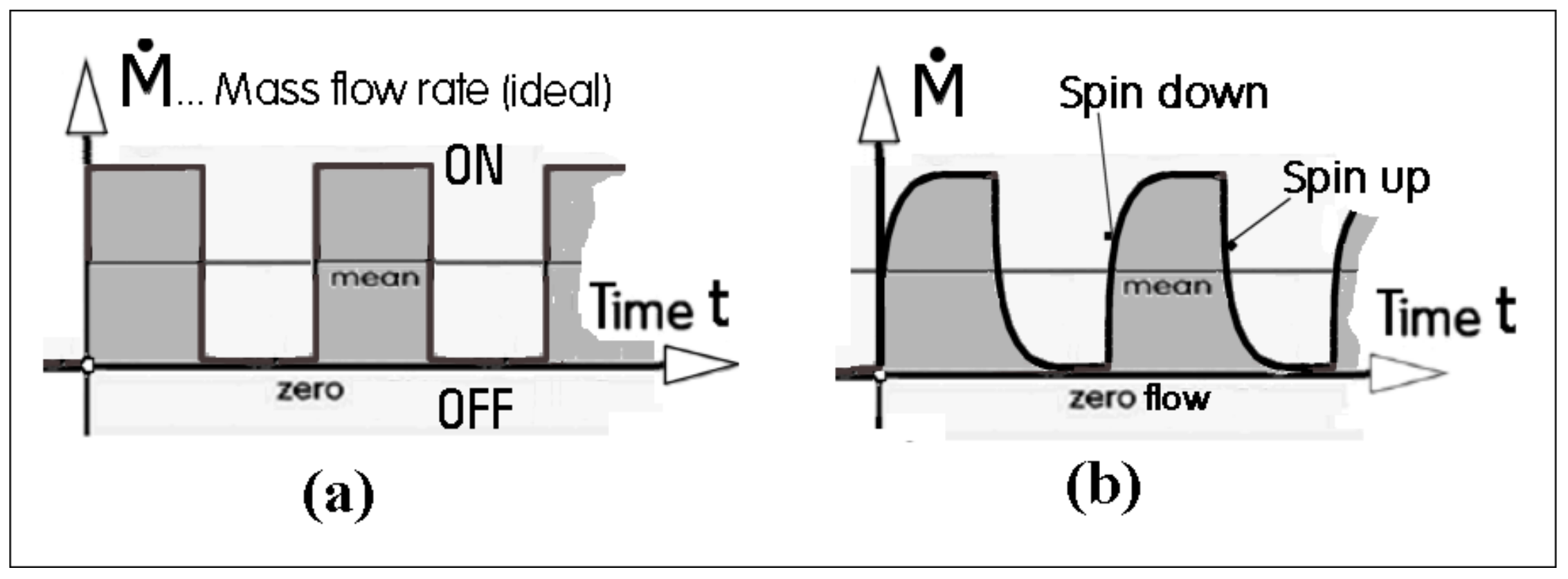
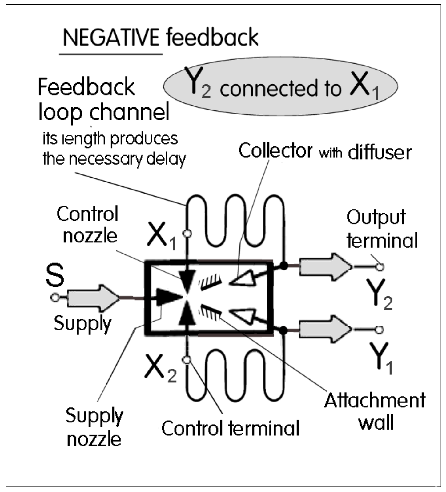
The standard present-day method of flow pulses generation in fluidics is in direct analogy to the principle used in electronics [3]. The no-moving-part fluidic amplifier is provided with terminals connecting the negative feedback channel loop. A typical example is described in a historic document [4]—somewhat complicated by a pair of feedback channels because the typical jet deflection flow-diverter amplifier is an integrated version of two amplifiers operating in anti-parallel. The pulse train, Figure 1, rather than harmonic oscillation is generated by using the Coanda-effect [5] of jet attachment to walls, Figure 2. The jet is switched alternatively between the walls and hence between its deflected flows. The feedback must have two essential properties. The first one is the negative character of the feedback. This means an increase in the output flow rate is delivered by the loop to the input, causing there a decrease of the deflection. The other necessary property of the feedback is the presence of a certain time delay in the feedback. If it were absent, the jet would probably stay in some sort of equilibrium between both outputs.
There are three alternative ways of how to achieve the delay. The already mentioned standard method is the fluid propagation speed in a channel. Schematic representation is shown in Figure 2 for the oscillator version corresponding to [4]. This feedback is used in typical regimes encountered at frequencies from f~10 Hz to f~100 Hz,dependent on the size scale; the smaller the amplifier, the higher the frequencies. Of course, the smaller size means smaller output power that may not suffice for some applications. Results of extensive measurements of the fluid flow delays in a wide range of oscillation frequencies are presented in [6]. With moderately sized amplifier and very short feedback loop lengths, the highest attainable oscillation frequencies are around f~100 Hz.
Another method of generating the delay in fluidics, according to [7], was developed for flow control in a wind tunnel where the required frequencies were higher than the above limit. The solution was found in using the resonance of traveling pressure waves. Pulses generated when the jet is switched generate in the attached resonator tube a wave propagating to the tube free end. From there the pressure waves are reflected as expansion ones, propagating back towards the amplifier. The waves travel fast so that the experimental data presented in [8] demonstrated that with the same bistable diverter amplifier as used earlier with the usual channel loop, it was possible to get regular oscillation at frequencies up to and above f~300 Hz.
There are special examples of very high-frequency oscillators, such as an exceptional case [9] which somehow manage to suppress the base frequency and transfer the driving energy to a higher (usually third) harmonic. They deserve further investigation because their operating mechanism is far from being fully understood.
3. New Captive Vortex Delay Principle
The new method of the delay generation discussed here is based on spin-up of fluid passing through a cylindrical chamber with a tangential inlet and central exit. This is an invention originating as an opposite request for very low frequencies. The problem there was not so much a physical oscillation limit but, instead, simply an inconvenience. For the low frequency f~2.79 Hz in [6] the used feedback tubes necessitated loop lengths as large as 50 m. Stowing this length of tubing of 10 mm internal diameter occupying a large volume caused unpleasant problems. Also, the reliability of the switching with signal propagation in the tubes of similar lengths was endangered—the moving fluid lost much of its transferred energy by internal friction.
The third feedback loop idea, suitable mainly for operation at low frequencies, is a new recent development. Compared with other delay generating methods, it is characterized by compactness. The most important object in the device is a body with cylindrically shaped internal cavity—the vortex chamber with a tangentially oriented fluid inlet at the circumference and an axially directed exit from the chamber center. This configuration itself is not new; it has existed in fluidics, known as the vortex diode. Such diodes have several different alternative design variants, aimed at improving performance, such as having two or even more tangential inlets, two oppositely located central exits, and variously shaped exits, although all of them share the same function principle. The common basic feature is the very high resistance in the regime of fluid rotation inside the vortex chamber. Its high resistance in the turned-down regime (backward flow) is generated by the action of centrifugal forces acting on the rotating fluid.
This vortex device has been used by researchers for three different purposes as follows:
- (a)
- Use as a diode. It exhibits very different resistance values for different (forward and backward) fluid flow directions.
- (b)
- Fluidic resistor with large cross-sectional areas. Despite the high resistance for the fluid flow, the device allows passing through it a quite large solid object [10].
- (c)
- (d)
- The new generator of delay in oscillators and pulse shapers.
The inventor of the vortex diode, for which he was granted a patent in 1928, was Thoma [15] at the Technical University in Munich, Germany. He assigned the laboratory measurements of the hydraulic properties of this device to his student Heim as the subject of his dissertation. This work was published [16] and direct continuation [17]. After this publication, later publications were based by authors other than those from Munich. Early publications were mostly patent applications, like [18] which introduced two tangential inlets on the mutually opposite chamber sides to achieve symmetry of the vortex flow. Later design [19] had four tangential inlets.
Obvious potential applications were initially seen in fluidic pumps in which the vortex diodes sought to replace the usual mechanical suction and delivery valves. The difficulty was the rather slow dynamics of vortex generation. This is used in the present paper but in the fluidic pumping applications it was seen as nuisance as it limited the frequency of reciprocating motion and hence caused considerable backward flow losses. Precedence was thus given in fluidic pumping developments to other types of fluidic diodes.
Of the items listed from (a) to (c) above, the most promising was the superquadratic stationary behaviour (c), replacing the usual high Reynolds number quadratic characteristics of fluidic device. The first demonstration of the exponent higher than 2.0 was discussed in [11]. This phenomenon of more rapid increase of pressure difference with increasing flow offers a number of applications, like those in flow rate measurement [12], or gagging of the inlet to the evaporator tubes of steam generators [13]. Some other related uses, like e.g. flood protection [10], are discussed in ref. [14]. Of course, the main advantage of vortex diodes—like of fluidic devices in general—is the absence of mechanical movable or deformed components, suitable for applications at high-temperature and acceleration levels. The high temperature use in salt-cooled nuclear reactors is subject of [20]. The recent investigation report are directed at very small micro-diodes [21] with potential applications in microfluidics [22] and also in mixing of fluids in microchemistry [23]. Important readings are [24] and [25].
4. Large Scale Pulse Shaper
A wholly new alternative to the so far known usual pulse duration delays in fluidic oscillators is the delay time mechanism with spin-up in a vortex chamber. Even for very low oscillation frequencies this new approach does not need a large accumulation or very long flow channel components. In principle the delay effect is the subject of patents [26,27]. The delays are obtained by employing the relatively long time needed by the vortex before it attains its full rotation speed, starting with zero rotation and radial flow to the central exit.
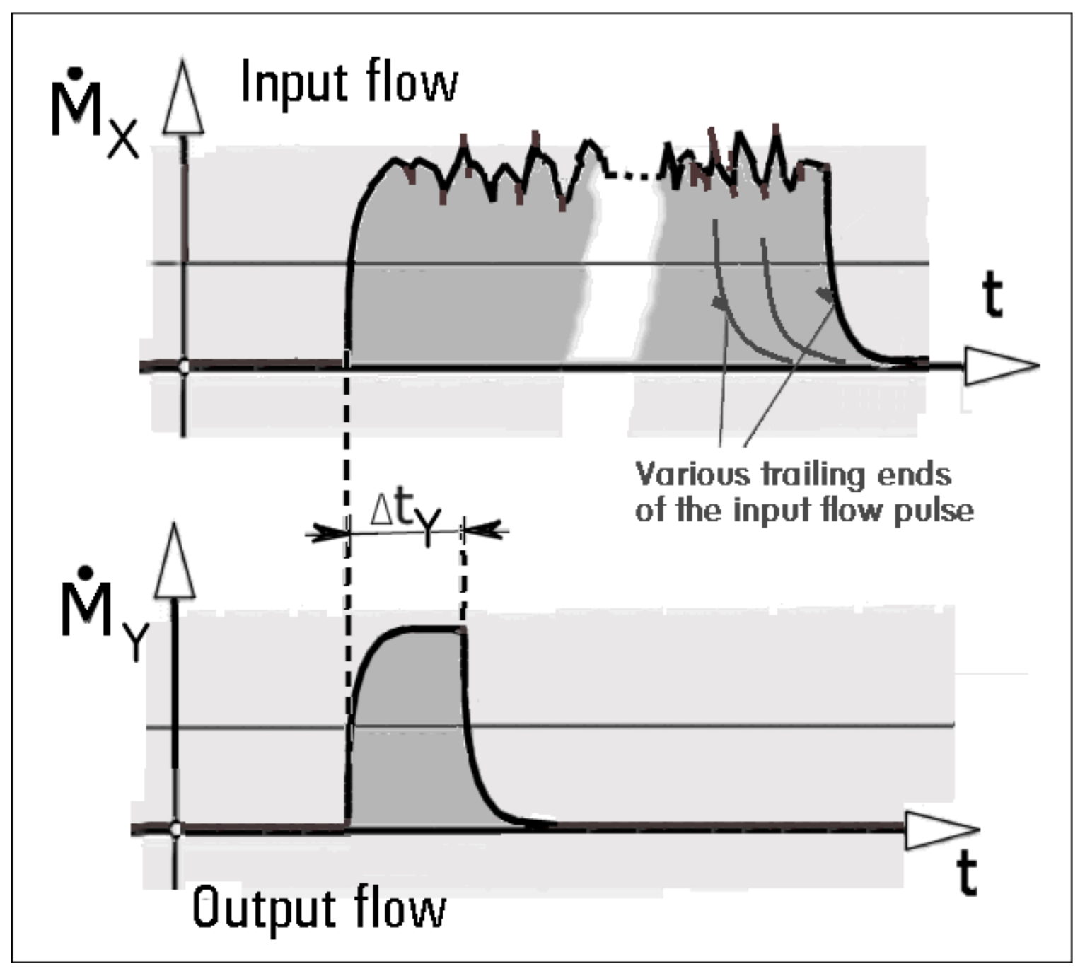
The subject discussed in [28] is a device for pulse shaping, such as that shown in Figure 3. The top diagram is representative of input pulses with typically corrupted shape and uncertain lengths; this length uncertainty is shown by the empty gap between the leading and trailing edges of the pulse. Initially, without the rotation, the flow through the device is easy and the leading edge of the output flow copies the flow rate at the input. Afterwards, the output attains a constant output value of the flow and this leads to the flat top of the pulse. Always the same pulse length ΔtY comes at the end: the output flow rate begins to be decreased to zero and remains at zero until the arrival of another input pulse.
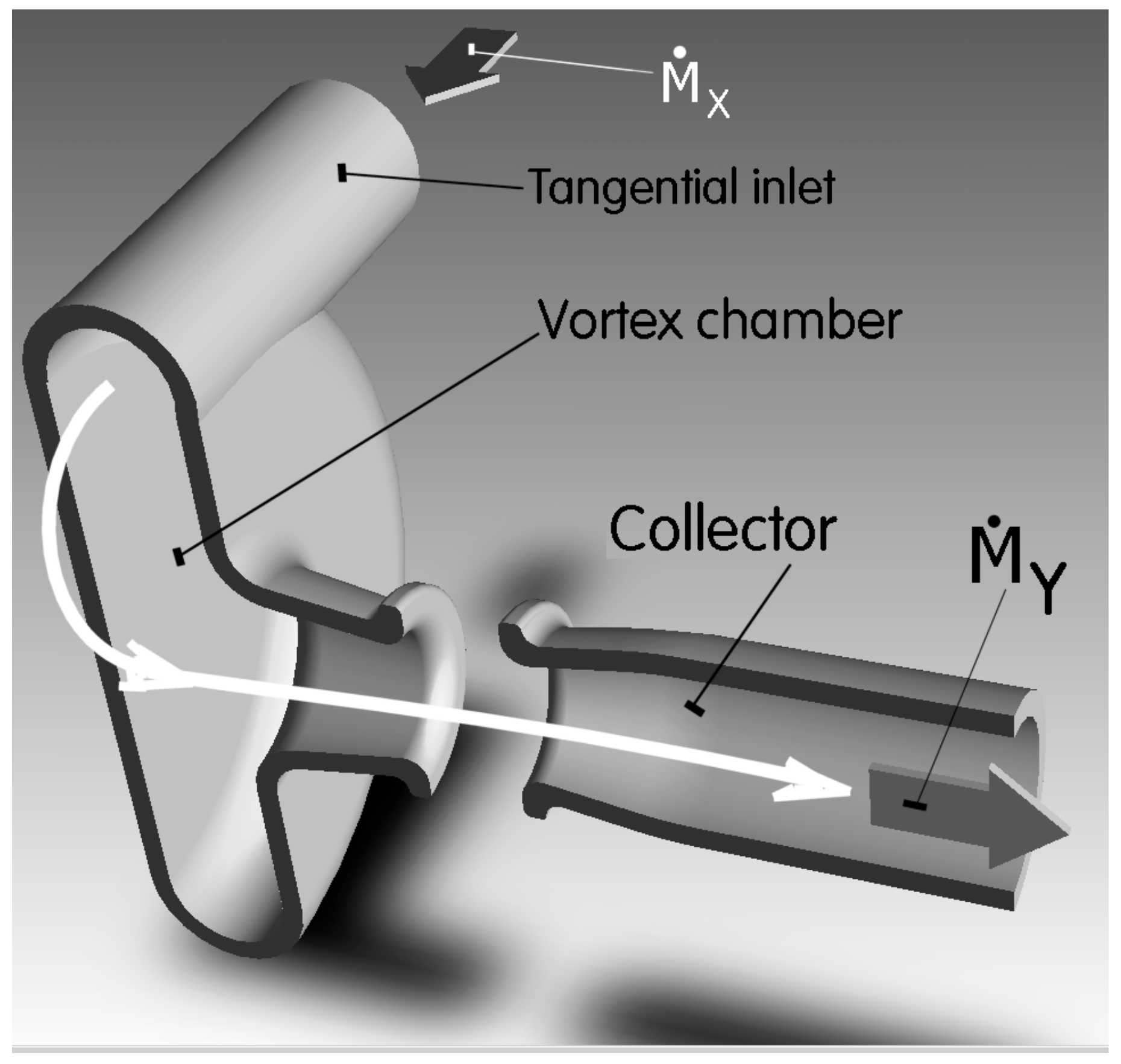
The pulse shaper device is presented in Figure 4 and Figure 5. It was originally developed for the pulse shaping task in power fluidics for which there are typical circular cross sections of flow tubes and pipes and also a rather complex three-dimensional spatial arrangement. The working fluid in the tests with this device was air. The device consists of two parts separated by a gap. Both are in the illustrations below, drawn in an imagined section by the cutting plane passing through the symmetry axis of the vortex chamber, which is at the left part of the image. On the right-hand side is the second component, the collector. The gap is open to the atmosphere. The mutual position of the two parts is kept by connecting components which, being of no importance for the operation, are not shown. The inlet of the air into the vortex chamber is arranged tangentially, in Figure 4 on the chamber top. If there is an input flow, this orientation generates a rotational motion inside the vortex chamber, the flowpaths of which are shown by the white curved arrows. The fluid exit from the vortex chamber is through the short-rounded pipe fixed to the chamber center, of internal cross section which decreases in the flow direction so that the air flow there is accelerated. The pipe is directed towards the inlet into the collector on the opposite side of the gap.
The operation of the device follows the two diagrams in Figure 3. At the beginning, the fluid inside the device is steady, not moving. The operation starts by arrival of an air flow pulse into the tangential input. It passes quite easily through the whole device following the white curved arrow in Figure 4. This easy flow is the consequence of the fact that there is initially no rotation inside the vortex chamber. On leaving the exit from the short tube at the vortex chamber axis, a jet of round cross section is formed issuing into the gap. Because of the inertia of the moving fluid, accelerated by the area contraction inside the short pipe, the jet crosses the gap with minimal opposition. After crossing the gap, the flow is captured by the collector. Downstream from the collector entrance the fluid passes through the flow section with cross-section area which increases in the flow direction. This decreases the kinetic energy of the captured jet flow and increases the air pressure there. The recovered pressure at the right-hand end of the collector is thus quite high. Also, the output flow rate in the exit shown in the bottom diagram in Figure 3 starts to rise.
The tangential orientation of the inlet into the vortex chamber causes the incoming fluid in the chamber to rotate around the symmetry axis. Initially the rotation is slow, the input flow is opposed by the inertia of the fluid inside. The mass flow rate in the bottom diagram in Figure 3 initially increases rather rapidly. Soon, however, the intensity of the rotation inside the vortex chamber increases which makes the flow through the device more difficult. If there were to be no friction on the vortex chamber walls, the moment of momentum of the rotation inside the vortex chamber would be constant. This means an increasing rotation speed as the fluid progresses from the chamber rim towards its central exit. With the increasing rotation speed, the centrifugal force acting on the rotating air also increases. Near the exit from the chamber the rotation speed becomes so high that it is difficult for the fluid to get to the center. The output flow rate curve in Figure 3 thus reaches its horizontal part. Shortly after, this white arrow curve shown in the bottom diagram in Figure 3 turns downwards. The output mass flow rate becomes very small. Moreover, the air flow that manages to get through the vortex chamber to its exit, from its strong rotation and the consequent centrifugal action, forces it to form a swirling radial jet, as seen in Figure 5. The air flow leaves through the gap into the atmosphere and the flow rate in the pulse shaper exit becomes zero. It remains at this zero-value for as long as there is an input flow at the tangential entrance into the vortex chamber, driving there the rotation. Once this input flow stops at the trailing edge of the input pulse, the rotation inside the cortex chamber ceases as it is slowed down by friction on the chamber walls. The device is then ready to process another input pulse flow. The duration and other characteristics of the output flow pulse are thus not influential. The generated pulses are of the same duration ΔtY.
5. Planar Pulse Shaper
The wholly new alternative to the pulse shaper of Figure 4 and Figure 5 is presented in Figure 6. It consists of two main components, a monostable flow diverter with attachment wall (at the left) leading tangentially to the vortex chamber (at the right). At the extreme left is the input terminal X. The working fluid, air, comes into it from the circular hole drilled in the rectangular substrate below the main plate. Additionally, in the center of the vortex chamber has a drilled similar perpendicular hole. This has the role of the output terminal Y. At the top of the picture is the vent V space, open to the atmosphere. For fluid flow away from the input terminal X serves the nozzle from which an air jet issues, represented in Figure 6 by the wide grey curved arrow. Figure 6 shows the position it assumes at the beginning of the device operation. The air at that instant is stationary in the vortex chamber and thus it can move after the arrival of the input pulse into X easily through the whole of the vortex chamber. It enters the chamber tangentially, directed there by the inclined attachment wall. This inclination forces the fluid inside the chamber to rotate, similarly to that discussed above for the vortex chamber in the previous section. The pressure difference ΔP defined in Figure 6 as the difference of pressure across the vortex chamber radius gradually increases as the rotation increases in speed. For the explanation of the behaviour the diagram shown in Figure 7 may be useful. Presented there are two curves separated by time interval D. They show the pressure difference indicated in Figure 6 as a function of time. There is a limiting magnitude ΔPsw above which the inertia of the incoming jet flow cannot allow it to enter. The jet flow therefore separates from the attachment wall and leaves via the vent V. For some time the fluid inside the vortex chamber continues rotating at a gradually decreasing rotation speed. Of course, in this spin-down regime the pressure difference is seen in Figure 7 to decrease and finally stops. When the next pulse comes after the time interval D, it finds attachment to the wall again and is prepared for the generation of the next rotation.
Only the instant of the initial impulse for performing the pulse shaping process is determined by the pulse arrival from the input X. From then on the whole pulse shaping procedure is independent, apart, of course, from using the fluid that it has brought. Figure 7 emphasises the fact that all generated pulses, however deformed, last tor the same time period Δtp,unless, of course, the input pulse at Xis too small.
6. Planar Low-Frequency Oscillator
6.1. Version with Two Vortex Chambers
The fluidic oscillator presented in Figure 8 with its schematic dependence of pressure on time with two output terminals is immediately recognisable as integrated into a single unit two anti-parallel circuits from Figure 6. They share only the common supply nozzle and the deflected jet generated in it. The integration results in the central part of Figure 8, a bi-stable jet-deflection diverter with alternating attachment to one of the two attachment walls. This diverter is not a bi-stable amplifier although it is very similar because there are no input terminals. In contrast to the usual design of diverters with a diffuser connected to each collector, here they would be useless because it is necessary for the fluid to enter the vortex chamber with sufficiently high velocity. Instead of the usual switching by control flow from the control nozzle, here the diverter is switched in response to the increasing pressure in the active vortex chamber upon reaching the limit pressure difference ΔPsw. The phase shift between delivering the fluid into the vortex chambers 1 and 2 shown in the diagram of pressure dependence at the bottom of Figure 8 is of course achieved automatically due to the sharing of the common jet. The bicuspid form of the splitter between the collectors generates a positive feedback action preventing any unwelcome early switching.
The key difference between the pulse shapers and oscillators is not recognisable from cavity geometry drawings because the cavities of both may be identical. The difference is in the character in which they are supplied with the fluid flow. The pulse shaper, e.g. in Figure 6, is a passive device driven by the input pulse supplied into the inlet terminal X. On the other hand, an oscillator, such as the one shown in Figure 8, is an active device. This means it is connected by its supply terminal S to a permanent fluid flow from an external constant flow (or constant pressure) source.
6.2. Single-Vortex Oscillator with Rapid Spin-Down
In all cases discussed above so far the spin-up inside the vortex chamber is achieved by the driving tangential inflow—while the spin-down in the second part of the oscillation period is passive. The rotation inside the chamber gradually slows by the absence of the driving input as well as by the friction on the chamber walls. To enhance this friction effect, the cylindrical geometry of the vortex chambers is in these applications characterised by a narrow space for the fluid rotation i.e., the cylindrical cavity is of small height relative to its outer diameter.
There is, however, a possibility to increase the deceleration taking place in the spinning down regime. For this effect the kinetic energy of the jet deflected away from the attachment wall in Figure 6 is used, which is otherwise simply left to dissipate the jet energy in the vent V.
Two examples of such configurations achieving this braking effect are presented in Figure 9. Shown there are sections of a plane passing in the middle of the cavity height. The spinning-up tangential inflow into the vortex chamber is the same as in Figure 6, but in the spin-down regimes of Figure 7 the jet enters the vortex chamber radially. It collides there with the tangential flow, slows down the rotation and makes this regime shorter and better controllable. It may be interesting to compare the resultant configuration of the cavities with the fluidic amplifier discussed, e.g., in [26]. This amplifier combines the otherwise unattainable combination of two properties: the bi-stability by jet deflection in the pre-chamber with the capability of turning down the supplied fluid flow.
6.3. Experiments
Experimental verification of the ideas was focused on the latest among the single-vortex configurations, the case B shown in Figure 9. The development of the used model was laborious as it required tests of several alternative gradually changing cavity shapes. All of them were of the same vortex chamber diameter D = 52.3 mm. The cavities were laser-cut in PMMA polymethylmethacrylate plates h = 2 mm thin, fixed by eight screws between the very thick top and bottom PMMA cover plates that closed the cavity and with their large thickness ensured mechanical solidity of the whole assembly. The air flow inlet S and outlet on the center of the vortex chamber were drilled holes in the bottom cover plate.
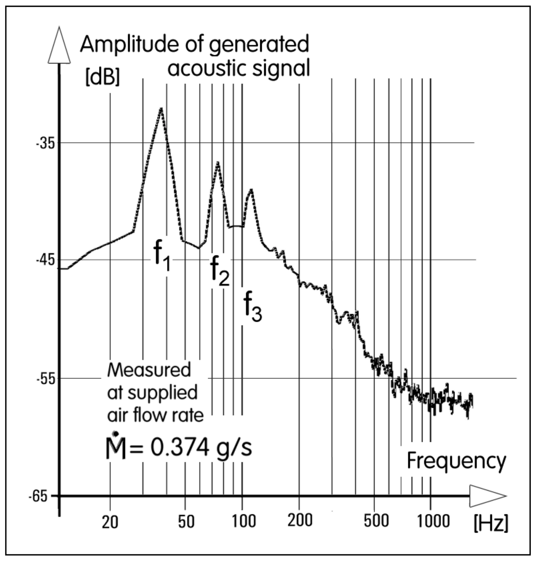
A photograph of one of the tested main plates is presented in Figure 10. The final geometry dimensioning is in the workshop drawing shown in Figure 11. The desirable behaviour necessitated making by a cut-and-try process several adjustments, e.g., the small cut-out in the vortex chamber wall (of the radius r 3.26 mm ending by the plane at 26.03 mm) at the downstream end of the preferential attachment wall. Interestingly, the experimental set-up was very simple, the oscillator model was supplied by compressed air at a rate measured by an electronic mass flow-meter FMA1827 (manufactured by OMEGA Engineering, Inc., Norwalk, CT, USA) capable of measuring the flow rate up to nominally 50 g/min. The output from the oscillator was measured by an anemometer CTA 54T30 (DANTEC Dynamics, Skovlunde Denmark), with a single hot wire probe type 55P16 (Dantec Dynamics). The linearized signal was processed by a computer provided with software performing fast Fourier transformation. The fundamental frequency f1, obviously corresponding to the jet switching between the preferential and auxiliary attachment walls, was apparent in the spectrum at the highest dominant peak. It was accompanied by the lower peaks of the harmonics f2 and f3, see Figure 12. Values of the peak frequencies were then read digitally. The f2 is twice as high as f1.
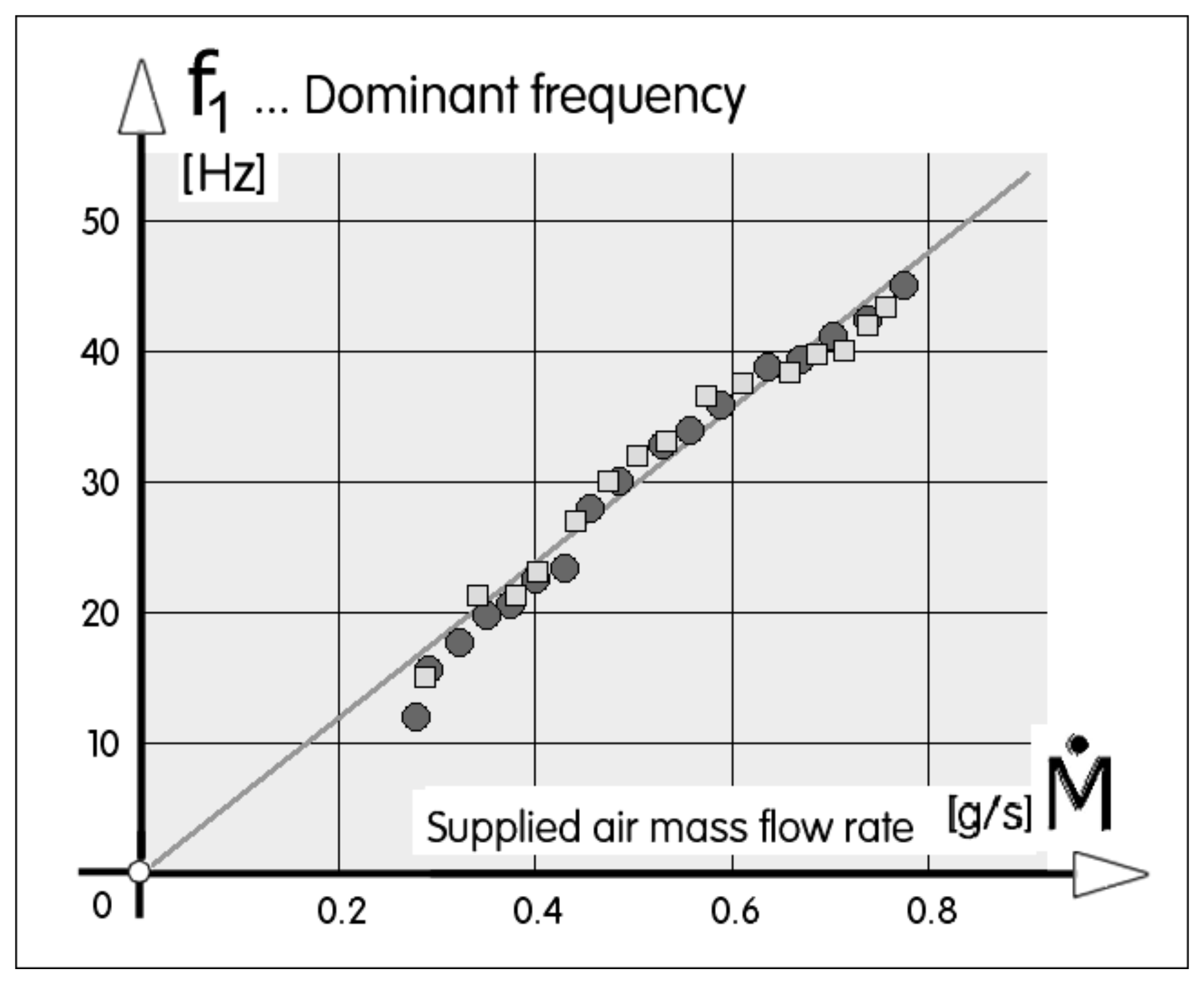
The character of the oscillations in fluidics is determined by the dependence of the fundamental frequency f1 on the supplied flow rate. In most devices in fluidics a dependence analogous to Figure 13 is found, where the linearity of the fit indicates the constancy of the Strouhal number and f3 is three times as high. The software operated with sampling frequency 8 kHz; the number of samples taken at each flow rate was 262,144 values.
where b [m] is the supply nozzle width and w [m/s] is the bulk velocity in its exit. The other case of feedback by resonance [7] is even simpler, with constant f1.
The range of measured fundamental
frequencies in the experiment was from f1 = 11.7 to f1 = 45.26 Hz (the upper limit determined merely by the range of the used flow-meter). Dependence of the fundamental frequencies on the supplied flow rate is presented in Figure 13. It is obvious that with the exception of very low frequencies, below the flow rate approximately
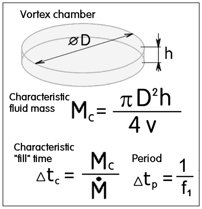
~0.3 g/s where the oscillation was slowed down by increased influence of friction, the dependence in Figure 13 is linear so that the discussed oscillator belongs to the standard family of fluidic oscillators. Because of the interest here focusing on time delay, it became interesting to evaluate the basic parameters as shown in Figure 14—the characteristic mass Mc [kg] of the fluid inside the chamber,
where D [m] is the outer diameter, h [m] is its internal height (Figure 14), and v [m3/kg] is the specific volume of the fluid. From these magnitudes it is possible to evaluate the characteristic time Δtc [s]
evaluated by dividing the characteristic mass of the vortex chamber contents by the supplied fluid mass flow rate. Let us assume that the device is operated as a fluidic oscillator at the fundamental frequency f1. The time between the oscillation pulses is the period
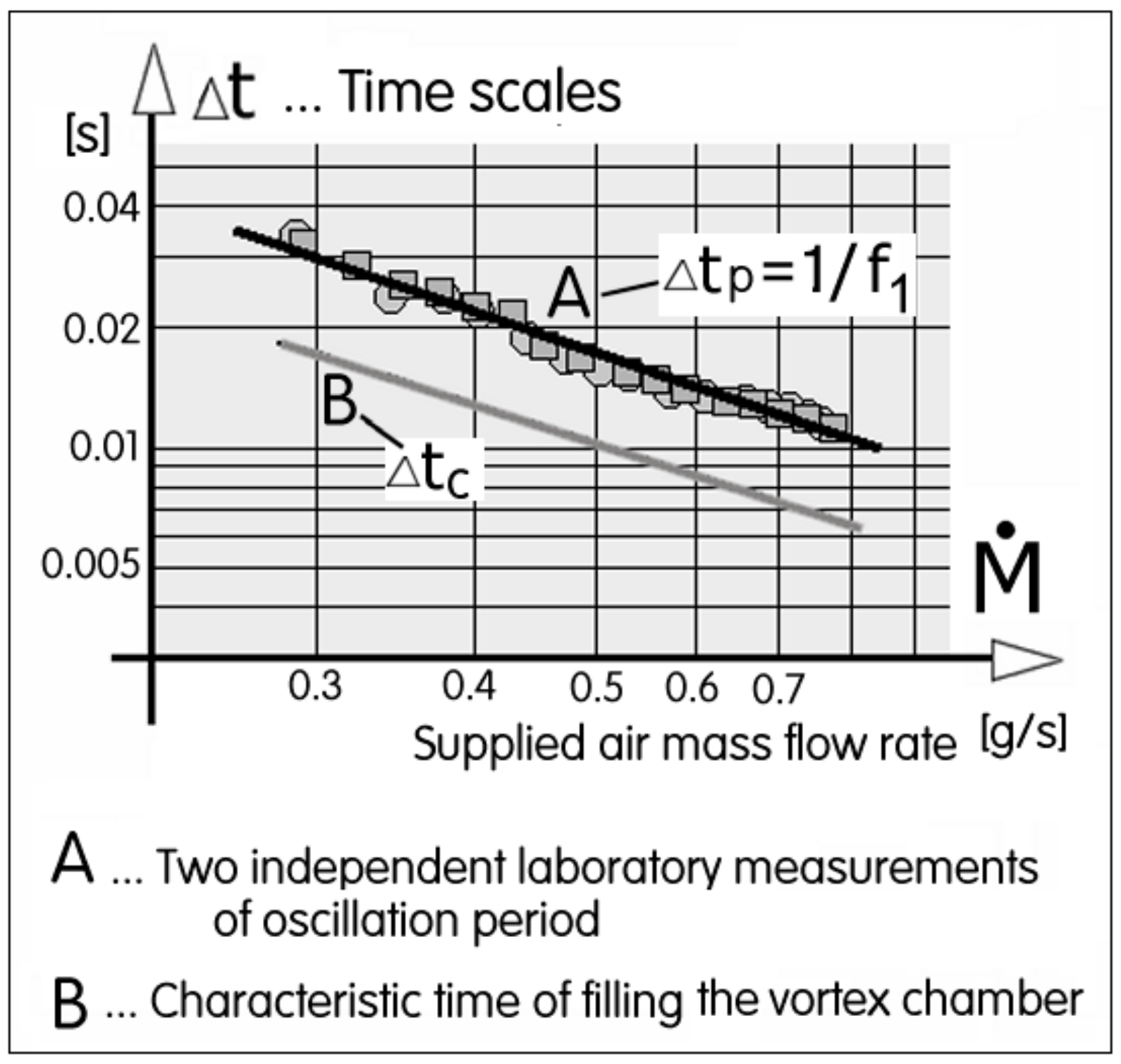
Both times Equation (3) and (4) are compared for the same particular mass flow rate (note the logarithmic co-ordinates used for plotting) in Figure 15.
6.4. Invariant of Vortex Chambers
Of course, the three-dimensional flow with substantial boundary layer friction on the dominant walls is very complex. Nevertheless, the remarkable constant distance between two plotted lines of characteristic times in Figure 15 gave rise to an idea of a rather simple behavioural theory based on the easy-to-evaluate parameter presented in Figure 14. The theory results in an expression—in its basic expression somewhat related to the Strouhal number—for an invariant of the device:
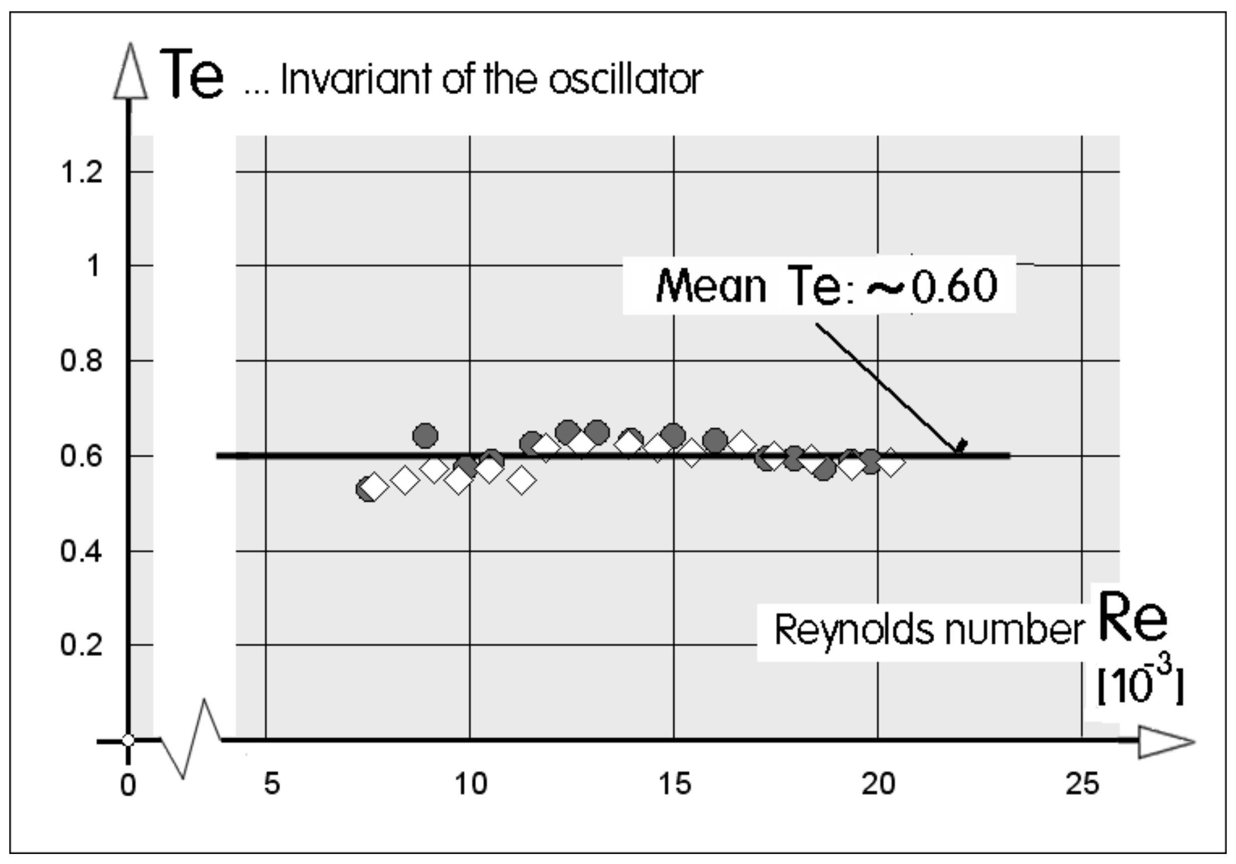
Correctness of this idea is demonstrated in Figure 16, where on the horizontal co-ordinate the Reynolds number of nozzle flow is plotted, while on the vertical co-ordinate the proposed invariant Equation (5) is plotted. With reasonably small scatter, data for the twice repeated experiments (altogether with 30 data points) show the constant mean value with the evaluated standard deviation
7. Conclusions
Signals exchanged between components of fluidic circuits nowadays increasingly often possess the character of pulse flows. For definition of the pulses, the fluidic circuit has to possess sub-circuits for definition of the time delays—the most important among pulse parameters. So far the absolute majority of delay defining sub-circuits measures the time by the distance covered by fluid flow in a channel.
This paper discusses a new and little known delay definition principle. It is based on the dynamics of rotation spin-up of a vortex kept captive inside a cylindrical cavity with a tangential flow inlet and a central outlet. Several fluidic circuits using this principle are discussed. Particularly useful may be an oscillator captive vortex feedback sub-circuit which also explains the author’s approximate theory of oscillation frequency. Applied to the author’s investigated oscillator, the simple mathematical model predicted the oscillator behaviour differing only by a numerical value of the oscillator invariant.
Funding
The author received institutional support RVO:61388998 from the Institute of Thermomechanics of Czech Academy of Sciences. Also obtained was support from GAČR grant agency by research grant No. 17-08218S.
Conflicts of Interest
The author declares no conflict of interest.
References
- Rehman, F.; Medley, G.J.; Bandulasena, H.; Zimmerman, W.B. Fluidic oscillator-mediated microbubble generation to provide cost effective mass transfer and mixing efficiency to the wastewater treatment plants. Environ. Res. 2014, 37, 32. [Google Scholar] [CrossRef] [PubMed]
- Tesař, V. Enhancing impinging-jet heat or mass transfer by fluidically generated flow pulsation. Chem. Eng. Res. Des. 2009, 87, 181. [Google Scholar] [CrossRef]
- Armstrong, E. Wireless Receiving System. U.S. Patent 1,113,149, 29 October 1913. [Google Scholar]
- Warren, R.W. Negative Feedback Oscillator. U.S. Patent 3,158,166, 7 August 1962. [Google Scholar]
- Coanda, H. Device for Deflecting a Stream of Elastic Fluid Projected into an Elastic Fluid. U.S. Patent 2,052,869, 1 September 1936. [Google Scholar]
- Tesař, V.; Hung, C.-H.; Zimmerman, W. No-moving-part hybrid-synthetic jet actuator. Sens. Actuators A 2006, 125, 159. [Google Scholar] [CrossRef]
- Tesař, V. Fluidic Oscillator with Jet-Type Bistable Amplifier. CZ Patent 303 758, 5 August 2011. [Google Scholar]
- Tesař, V.; Zhong, S.; Rasheed, F. New fluidic-oscillator concept for flow-separation control. AIAA J. 2013, 51, 397. [Google Scholar] [CrossRef]
- Tesař, V. High-frequency fluidic oscillator. Sens. Actuators A Phys. 2015, 234, 158–167. [Google Scholar] [CrossRef]
- Brombach, H. Flood protection by vortex valves. ASME J. Dyn. Syst. Meas. Control 1981, 3, 338. [Google Scholar] [CrossRef]
- Tesař, V. Superquadratic behaviour of vortex diodes. Pneumatic and hydraulic Components. In Proceedings of the IFAC Symposium, Warsaw, Poland, 20–23 May 1980; p. 79. [Google Scholar]
- Tesař, V. Apparatus for Measurement of Fluid Flow. CZ Patent 195802, 31 August 1977. [Google Scholar]
- Tesař, V. Gagging of the Inlet of Liquid into Evaporator Tubes of a Steam Generator. CZ Patent 192856, 1 September 1977. [Google Scholar]
- Tesař, V. Superquadratic fluidic restrictors and their applications. Advances in Fluid Mechanics IX. In WIT Transactions on Engineering Sciences; WIT Press: Southampton, UK, 2012; Volume 74, p. 507. [Google Scholar]
- Thoma, D. Fluid Lines. U.S. Patent 1,839,616, 11 June 1928. [Google Scholar]
- Heim, R. Versuche zur Ausbildung der Thomaschen Rückstrombremse; Mitteilungen des Hydraulischen Instituts der TH München: Oldenbourg, Germany, 1929; Volume 3. [Google Scholar]
- Zobel, R. Versuche an der hydraulischen Ruckstromdrossel; Mitt. Hydraulischen Instituts der Technischen Hochschule Munchen: Oldenbourg, Germany, 1936. [Google Scholar]
- Gibson, T.M.S. Fluid Flow Control. U.S. Patent 2893432, 31 December 1953. [Google Scholar]
- Lorenz, W.T. Fluid Regulator. U.S. Patent 3198214, 30 October 1963. [Google Scholar]
- Yoder, L.Y.; Elkassabgi, Y.; DeLeon, G.; Fetterly, C.; Ramos, J.; Robbins, J.; Cunningham, R.B. Vortex Diode Analysis and Testing for Fluoride Salt-Cooled High-Temperature Reactors; Oak Ridge National Laboratory Report TM-2011/425; Oak Ridge National Laboratory: Oak Ridge, TN, USA, 2012.
- Fouladi, K.; Czupryna, J. CFD-based optimisation of micro vortex diodes. J. Appl. Mech. 2018, 11, 1231. [Google Scholar]
- Tesař, V. Pressure-Driven Microfluidics, Monograph; Artech House Publishers: Norwood, MA, USA, 2007. [Google Scholar]
- Tesař, V.; Low, Y.Y. Study of shallow-chamber vortex mixers for microchemical applications. In Proceedings of the 9th International Symposium on Flow Visualization, Edinburgh, UK, 22–25 August 2000. No. 445. [Google Scholar]
- Wormley, D.N.; Richardson, H.H. A design basis for vortex-type fluid amplifiers operating in the incompressible flow regime. J. Basic Eng. 1970, 92, 369. [Google Scholar] [CrossRef]
- Kulkarni, A.A.; Ranade, V.V.; Rajeev, R.; Koganti, S.B. Pressure drop across vortex diodes: Experiments and design guidelines. Chem. Eng. Sci. 2009, 54, 1285. [Google Scholar] [CrossRef]
- Tesař, V. Device for Adjusting Time Dependence of Fluid Flow. CZ Patent 202,898, 25 December 1979. [Google Scholar]
- Tesař, V. Fluidic Oscillator. CZ Patent 306,064, 15 December 2014. [Google Scholar]
- Tesař, V.; Smyk, E. Fluidic Low-Frequency Oscillator with Vortex Spin-Up Time Delay. Chem. Eng. Process. Process Intensif. 2015, 90, 6. [Google Scholar] [CrossRef]
Figure 1.
Schematic presentation of oscilloscope traces of pulsating flow with (a) ideally shaped rectangular pulses and (b) characteristic pulse shapes generated by the captive vortex devices.
Figure 1.
Schematic presentation of oscilloscope traces of pulsating flow with (a) ideally shaped rectangular pulses and (b) characteristic pulse shapes generated by the captive vortex devices.

Figure 2.
Schematic representation of the Warren’s [4] fluidic amplifier (black triangle: nozzle, white triangle: collector with output diffuser). The delays needed in the feedback loops, defining the pulse duration, are in this contemporary standard configuration produced by the flow progressing from Y to X. This paper introduces a different delay mechanism, with spin-up of captive vortices.

Figure 3.
Typical flow of a fluidic pulse shaper as seen in oscilloscope traces of mass flow rate. In response to the distorted input pulse (of various lengths, top) a standard duration ΔtYoutput pulse (bottom) is generated in the output terminal.
Figure 3.
Typical flow of a fluidic pulse shaper as seen in oscilloscope traces of mass flow rate. In response to the distorted input pulse (of various lengths, top) a standard duration ΔtYoutput pulse (bottom) is generated in the output terminal.

Figure 4.
Pulse shaper based on the idea of vortex spin-up according to [26]. The front part is shown here cut off by a meridian cutting plane. The white flow line represents the beginning of the inlet pulse.
Figure 4.
Pulse shaper based on the idea of vortex spin-up according to [26]. The front part is shown here cut off by a meridian cutting plane. The white flow line represents the beginning of the inlet pulse.

Figure 5.
The pulse shaper from Figure 4 in the regime of rotation inside the vortex chamber. Output flow in Y is zero because the fluid escapes through the gap between the two components.
Figure 5.
The pulse shaper from Figure 4 in the regime of rotation inside the vortex chamber. Output flow in Y is zero because the fluid escapes through the gap between the two components.

Figure 6.
Planar pulse shaper with the time delay derived from starting and increasing rotation in the vortex chamber. The pulse length is determined by the time when centrifugal force can no more keep the jet attached by Coanda-effect [5] at the attachment wall so that the jet is pushed away into the vent space V.

Figure 7.
Examples of the sequence of two pressure pulses at the output of the shaper shown in Figure 6. Between the pulses there is a long time interval D. In response to the input pulse arrival uniform output pulses are generated shown here as their time dependence on the pressure differences ΔP.
Figure 7.
Examples of the sequence of two pressure pulses at the output of the shaper shown in Figure 6. Between the pulses there is a long time interval D. In response to the input pulse arrival uniform output pulses are generated shown here as their time dependence on the pressure differences ΔP.

Figure 8.
Fluidic oscillator [27] generating simultaneously two mutually inversed-phase pulse trains. The two vortex chambers are switched between spinning-up by input flow and spinning down by friction on the chamber walls.
Figure 8.
Fluidic oscillator [27] generating simultaneously two mutually inversed-phase pulse trains. The two vortex chambers are switched between spinning-up by input flow and spinning down by friction on the chamber walls.

Figure 9.
Two alternative geometries of a load-switched oscillator with single vortex chamber and monostable diverter. Radial inflow R leaves the chamber without rotation generated by the tangential inflow T. Direct tangent entry (A) may exhibit lower energy loss while (B) without the ”island” inside the pre-chamber is easier to manufacture by etching the cavities on a thin plate.

Figure 10.
Photograph of one of the oscillator main plates with which were run the laboratory tests.
Figure 10.
Photograph of one of the oscillator main plates with which were run the laboratory tests.

Figure 11.
Workshop drawing of the plate with the final cavities. Note the different setbacks A and B compared to Figure 10 above. The geometry of cavities was developed from those of the amplifier discussed in [27].

Figure 12.
Measured spectrum of generated oscillation at a particular air flow rate.

Figure 13.
Result of measured fundamental oscillation frequency as a function of the supplied mass flow rate. Apart from the friction-dominated low-velocity lower end the dependence is well fitted by a linear function.
Figure 13.
Result of measured fundamental oscillation frequency as a function of the supplied mass flow rate. Apart from the friction-dominated low-velocity lower end the dependence is well fitted by a linear function.

Figure 14.
Basic parameters of the author’s elementary theory of vortex-chamber behavior.

Figure 15.
In the logarithmic co-ordinates the two characteristic time periods, Equation (3) and (4), are plotted as parallel straight lines A and B.
Figure 15.
In the logarithmic co-ordinates the two characteristic time periods, Equation (3) and (4), are plotted as parallel straight lines A and B.

Figure 16.
The extremely simple theory of the delay time caused by accelerating the rotation in the vortex chamber results in this invariance of the dimensionless number Te, defined by Equation (5).
Figure 16.
The extremely simple theory of the delay time caused by accelerating the rotation in the vortex chamber results in this invariance of the dimensionless number Te, defined by Equation (5).

© 2019 by the author. Licensee MDPI, Basel, Switzerland. This article is an open access article distributed under the terms and conditions of the Creative Commons Attribution (CC BY) license (http://creativecommons.org/licenses/by/4.0/).
Share and Cite
MDPI and ACS Style
Tesař, V. Delay by Spin-Up of Captive Vortex. Energies 2019, 12, 3341. https://doi.org/10.3390/en12173341
AMA Style
Tesař V. Delay by Spin-Up of Captive Vortex. Energies. 2019; 12(17):3341. https://doi.org/10.3390/en12173341
Chicago/Turabian StyleTesař, Václav. 2019. "Delay by Spin-Up of Captive Vortex" Energies 12, no. 17: 3341. https://doi.org/10.3390/en12173341
Note that from the first issue of 2016, this journal uses article numbers instead of page numbers. See further details here.