


Abstract
The presented experimental study realized in the COMPASS tokamak demonstrates, for the first time, that the current density that flows from the plasma into the vacuum vessel during disruptions is limited by the ion particle flux. Such a limitation shows that, at least in COMPASS, the sheath that forms between the plasma and the first wall dominates the halo current flow. This observation is achieved by measuring simultaneously the ion saturation current with negatively biased Langmuir probes and the halo current with grounded probes to the vacuum vessel. These comparative measurements, which were never performed during disruptions in other machines, directly confirm that the halo current density remains below the ion particle flux in COMPASS. The study also shows, using Mirnov coils measurement, that the total electric current entering the wall grows with the plasma current while the current density obtained by Langmuir probes remains unaffected. This, together with the current density limitation, leads to a novel finding that the halo current width increases with the pre-disruptive plasma current, which limits the local forces. The new findings reported here could also provide potential constraints on the modeling of disruption-induced loads on future reactor scale tokamaks and motivation for further experiments on existing devices.
Export citation and abstract BibTeX RIS

Original content from this work may be used under the terms of the Creative Commons Attribution 4.0 licence. Any further distribution of this work must maintain attribution to the author(s) and the title of the work, journal citation and DOI.
1. Introduction and motivation
Unmitigated disruptions [1] in large scale tokamaks, such as ITER and DEMO [2, 3], lead to a loss of plasma thermal and magnetic energy with timescales of milliseconds to tens of milliseconds respectively. The associated thermal and electromagnetic loads during disruptions may significantly limit the lifetime of tokamak components in future fusion reactors [4] so that their understanding and reduction is a major research priority for the development of magnetic confinement fusion as an energy source. Improved understanding of the physics processes responsible for the complex events that take place during disruptions is crucial to predict these loads and thus to determine the requirements for their mitigation. In turn, these predictions are performed on the basis of modeling that requires validation against experiments. In this respect, halo currents, [5–9], which are the currents flowing from the plasma into the plasma-facing components (PFCs) during the disruption current quench (CQ), are key for the understanding of the disruptive loads. These currents close their electrical circuit through the tokamak conducting structures by paths which are perpendicular to the dominant (toroidal) magnetic field. The halo current density therefore determines the local pressure exerted by electromagnetic forces on the tokamak components and affects the transient power fluxes deposited during disruptions onto PFCs. To date, the experimental characterization and extrapolation of halo currents in terms of their spatial distribution and magnitude have been carried out on a purely empirical basis.
Halo currents result from the voltages induced by the fast decay of the plasma current, Ip during disruptions (∼600 MA s−1 at the COMPASS tokamak) and the associated plasma vertical movement leading to an edge current flow whose current density is determined, if there were no other physics involved, by the edge plasma resistivity. However, well-known basic plasma physics processes [10] lead to the formation of an electric sheath when a plasma contacts material surfaces. This limits the maximum positive current that can flow from the plasma into the surface to the ion particle flux (also known as the ion saturation current). Recent non-linear resistive magnetohydrodynamic (MHD) simulations of COMPASS disruptive events [11] have shown that limiting the halo current density at the plasma–wall interface to the modeled ion saturation current has a dramatic effect on the halo current distribution and the overall disruption dynamics. Inclusion of sheath plasma effects for the power flow in simplified simulations of disruptions with the DINA code was found to have important consequences for the CQ dynamics and the modeled heat loads in these events in ITER [12].
In order to understand the halo current flow during disruptions and their impact on disruption dynamics and loads it is therefore essential to determine whether the sheath between the plasma and the contacting structures remains at work in the extreme conditions imposed by disruptive events. If this is the case, it is also necessary to assess if the existence of the sheath results in a limitation of the halo current density during the transient. Although it may appear to be a rather obvious physics process to take into account, the limitation of disruptive halo current density imposed by the sheath has, until now, not yet been considered in modeling studies of halo physics (with the notable exception of the recent studies mentioned earlier and [12]), which assumed that the halo current density was purely determined by the electric field created by the plasma during the disruption and the plasma resistivity. In part, this was due to the lack of an experimental confirmation that such sheath limit is at work during disruptions. In principle, sheath effects may not be playing a main role during disruptions and electric arcing could dominate the current flow instead due to large disruptive voltages. Pioneering measurements of halo current density profiles were performed in Alcator C-mod with Langmuir probes [14], however measurements of the ion saturation current were not done.
In this work, we provide first experimental evidence that the halo current flow density can remain limited during disruptions and, moreover, that the value of this limit is given by the ion saturation current, which does not depend on plasma resistivity. This experimental confirmation has been achieved by simultaneously measuring the ion saturation current and the halo current density during plasma disruptions in the COMPASS tokamak. In this respect, COMPASS is a device with an open graphite divertor configuration covered by an extensive array of Langmuir probes, which allows to capture a significant fraction of the halo region. In addition, our measurements indicate that due to this sheath-driven current density limit, the spatial extent of the halo current (the so-called halo width) increases with the magnitude of the pre-disruptive Ip.
2. Experiment arrangement and results
When the disruptive plasma contacts the PFCs, halo currents enter the vacuum vessel by passing through these components and its current density can be measured by Langmuir probes that are electrically connected to the vacuum vessel by shunt resistors R = 5.6 Ω (providing the grounded current density, Jground). Similar arrangements with Langmuir probes were also used on Alcator C-mod [14].
The COMPASS tokamak is equipped with a divertor Langmuir probe system [15] which is routinely used for measurements of fast transient events in divertor plasma configurations [16]. The rooftop-shaped Langmuir probes have a 20° chamfer with a total exposed area of S = 22 mm2 and projected area (on one side) of S⊥ = 2.8 mm2. Thus, each probe directly measures the halo current flow from plasma through the projected area. The probes are made of the same graphite material as the surrounding divertor tiles. It has been used to measure halo current densities over a range of pre-disruptive Ip with microsecond temporal resolution. Figure 1 shows two of the arrays (LPA and LPB) in the system comprising poloidal rows of rooftop-shaped, single Langmuir probes (55 probes per array) combined with an image taken by a fast visible color camera [17] at t = 1096.1 ms at the beginning of CQ phase of a disruption occurring in discharge #20833 (Ip = 300 kA, BT = 1.15 T). Note that the probe I–V characteristics do not exhibit any sheath expansion (figure 3 in [15]) and that neutral and collisional effects on the electrostatic and magnetic sheaths are not expected to play a role on the interpretation of the measured ion saturation currents for the plasma parameters measured during COMPASS disruptions. Figure 2 shows an equilibrium reconstruction during the disruption for the same discharge of figure 1. It is observed that the plasma column moves downwards to the divertor (shown by z time trace in figure 3). When the plasma contacts the wall, the halo current flows along the open magnetic field lines in the plasma, and closes its conducting path through the vacuum vessel wall (figure 2). The position of the plasma–wall contact point (pink cross) is shown at the last time point for which the plasma MHD equilibrium reconstruction can be performed.

Figure 1. The system of divertor probes with two arrays of roof-top shaped Langmuir probes on COMPASS and a fast visible camera frame during the disruption at the beginning of the thermal quench (t = 1096.1 ms) in shot #20833.
Download figure:
Standard image High-resolution image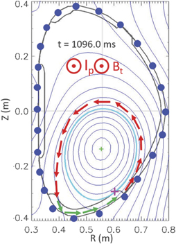
Figure 2. Plasma equilibrium reconstruction during the disruption of discharge #20833 at t = 1096.0 ms, the start of the CQ phase. Halo current path is shown by arrows (red while in plasma and green while in the vacuum vessel). Blue dots indicate Mirnov coils. The pink cross shows the first plasma contact point.
Download figure:
Standard image High-resolution image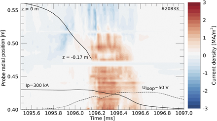
Figure 3. Temporal evolution of the current density of the grounded Langmuir probe array on the divertor with respect to their radial positions. The plot also shows the temporal evolution of the vertical position of the plasma column z, Ip and Uloop during the disruption in discharge #20833.
Download figure:
Standard image High-resolution imageThe corresponding temporal evolution of the halo current density, Jground, measured by the Langmuir probe array [LPB array on high field side (HFS) and LPA array on low field side] with the probe voltages fixed at 0 volts, is shown in figure 3 as well as the time traces of Ip, the loop voltage (Uloop) and the vertical position of the magnetic axis. The Uloop signal is measured by the flux loops located externally with respect to the vacuum vessel. At the beginning of the disruption (t < 1096 ms) the plasma column moves downwards (figures 2 and 3) while Ip remains unchanged. This corresponds to an unmitigated disruption caused by the so-called hot vertical displacement event (VDE), which is expected to lead to the largest loads on ITER tokamak components [4]. The decay of Ip in the CQ phase begins at t > 1096 ms and lasts ∼0.5 ms. Values of Jground in the range 1–2 MA m−2 are measured during the CQ phase, where the Uloop, which drives halo current flow, reaches values of ∼50 V. Note that such disruptive current densities are similar to the maximum current densities in the plasma core before the onset of the disruption in COMPASS (∼3 MA m−2) [7] and are also similar to the equilibrium current densities for ITER reference scenarios [18]. Most of the probes measure positive Jground during disruptions located on the HFS. In several dedicated discharges, we have compared the measured Jground to the ion saturation current density Jsat by applying a negative bias voltage Vbias < −100 V to a Langmuir probe located at the radial position ∼0.44 m (HFS) and comparing the grounded current to a poloidally neighbouring probe. Note, the effect of the secondary electron emission should not affect the Jsat measurements. When in ion saturation all electrons are repelled by the negative voltage (thus leading to ion saturation) and there are no primary electrons that could produce the secondary ones. Electron emission under ion flux could in principle take place but this would reflect itself in an increase of the collected current at high negative voltage. This effect is not observed for the (large) voltage range used in COMPASS experiments, see figure 3 in [15] for example. We have analyzed 18 discharges with disruptions and different pre-disruptive Ip. The results of this systematic comparison of Jground and Jsat + measurements (including the example from figure 3) is shown in figure 4. In all pulses we find that the Jground ⩽ Jsat + within experimental uncertainties (typically up to + 25% for high values of Jsat +, as shown in figure 4). For most discharges analyzed, Jground is limited at the Jsat + value throughout the disruption. There are a few specific pulses for which Jground is clearly lower than Jsat +. In such cases, the plasma driven electric field and the resistivity limit the halo current density and not the plasma sheath. These disruptions are 'nominally identical' to the others with the same Ip. Since the CQ is determined by plasma temperature and impurity content during disruptions and Jsat + is determined also by plasma density as well as temperature and impurity content, they can vary from disruptions which are 'nominally identical' and these variations lead to the measurements reported in figure 4. Note that although Jground can reach peak values of up to 2 MA m−2 (figure 2), we can only measure Jsat + ∼ 1.4–1.6 MA m−2 due to our power supply limitations and we restrict our comparison to this range.
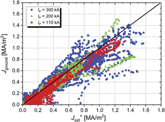
Figure 4. Comparison of grounded and ion saturation current densities at the HFS during the CQ for different pre-disruptive Ip. Results are extracted from 18 separate pulses. The ion saturation current density measurements are limited to maximum values of ∼1.4–1.6 MA m−2 due to power supply limitations and arcing.
Download figure:
Standard image High-resolution image3. Halo current and its distribution
While inside the vacuum vessel wall, the halo current magnitude can be measured by Mirnov coils. The COMPASS tokamak is equipped with three sets of discrete Mirnov coils (24 coils each) distributed across the poloidal cross-section of the vessel at different toroidal locations (figure 2, blue points), separated by 180° and 45°. Each depicted coil position has Mirnov coils measuring the three components of the magnetic field—radial, poloidal and toroidal. The latter is used to detect poloidal halo currents flowing in the vacuum vessel [19]. Here we use a set of coils, which is located approximately 135° toroidally (anti-clockwise) from the LPA probe array. This allows us to determine the maximum value of the poloidal halo current, which is located in the divertor region where the plasma–wall contact takes place. The halo current averaged over the poloidal cross-section IHalo avg measured at the vacuum vessel wall is found to increase with the pre-disruptive Ip as shown in figure 5. This current is proportional to the integral of the halo current density that flows from the plasma into the vacuum vessel. It can therefore grow due to an increase of the halo current density (Jground) over the same area, by an increase of the area over which the plasma–wall current flow takes place at constant, sheath-limited Jground, or by an increase of both Jground and area. To determine which physics process dominates in this experiment, we have evaluated the time-averaged radial profiles of the current density for different pre-disruptive Ip shown in figure 6. These profiles were obtained from a selected set of the disruptions in figure 4 within the time interval (∼200 μs) with the largest Jground values during the CQ. The results in figure 6 confirm that the maximum halo current density (Jground) is limited in COMPASS to values of typically <2 MA m−2 over the range of pre-disruptive Ip = 110–300 kA and different range of Uloop (max) values. As explained in the previous section, these maximum Jground values are similar to the measured ion saturation current density (JSAT +), as shown in figure 4. This demonstrates that the plasma driven electric field during the disruption, which is directly correlated with the pre-disruptive current and edge resistivity, do not determine the maximum value of the halo current density. This implies that the current density is limited by the particle flux, which is mainly given by the ion density at the plasma–wall interface. Since the IHalo avg increases by a factor of ∼4–5 in the pre-disruptive Ip range of 110–300 kA, the limitation of Jground to Jsat + results in an increase of the halo current width with pre-disruptive Ip. Note that the halo current width cannot be directly determined by the Langmuir probe measurements since the divertor arrays cover only ∼10 cm of radial distance at the HFS. Since the edge plasma (plasma density and temperature) as well as wall conditions (material properties with different secondary electron emission, ion reflection etc) impact sheath physics, we expect that wall conditioning, impurities and physics of the plasma–wall interaction during disruptions can play a major role determining the magnitude of the ion saturation current and the associated limitations to halo current density and resulting halo current width.
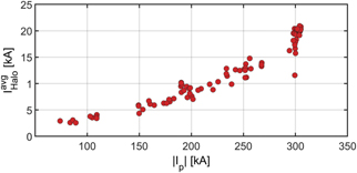
Figure 5. Absolute value of halo current averaged over the poloidal cross-section versus the magnitude of the pre-disruptive Ip.
Download figure:
Standard image High-resolution image
Figure 6. Time-averaged radial profiles of the grounded current density (Jground) during disruptions with different pre-disruptive plasma currents [Ip ∼ 300 kA (six discharges), 200 kA (two discharges), 110 kA (four discharges)].
Download figure:
Standard image High-resolution image
4. Conclusions
For the first time, the simultaneous measurements of the ion saturation current with negatively biased Langmuir probes and of the halo current with grounded Langmuir probes on the COMPASS tokamak, bring the experimental evidence that electric currents arising at the plasma edge during the CQ phase of tokamak disruptions (i.e. halo currents) are locally limited by the ion particle flux where the plasma contacts the wall. This implies that the sheath formed between the plasma and the material surfaces during this contact withstands the extreme conditions imposed by disruptions. This experimental confirmation has been possible by the use of divertor Langmuir probes on COMPASS, both with microsecond temporal resolution. The disruption-induced loop voltage is such that the current density measured at the wall surface remains almost always below the ion saturation current density for a range of pre-disruptive Ip of 110–300 kA with no dependence on Ip. Furthermore, the additional measurements of the halo current, using Mirnov coils, show that the total electric current entering the wall grows with the pre-disruptive plasma current while the current density obtained by grounded Langmuir probes remains unaffected. This, together with the observed current density limitation, leads to the major novel finding that halo current width increases with the pre-disruptive plasma current, which limits the local forces. Note that in reference [14], the parallel halo current density was not compared at different Ip and that the dependence of the halo width with Ip could not be studied. In this respect, one of the main advantages of the LPs employed at COMPASS compared to the ones employed at Alcator C-mod is that our probes form a significant angle with the toroidal field (∼20°), which allow to estimate the parallel current density despite the magnetic geometry changes caused by the Ip scan.
This work shows the importance of taking into account edge plasma physics and plasma–wall interactions during disruptions and VDEs for the understanding of disruption loads. It could also provide an important potential constraint on the modeling of disruption-induced loads on future reactor scale tokamaks. This constraint means that disruption modeling codes should limit the maximum current density to the ion particle flux, which can modify the distribution of the heat and electromagnetic loads. For example, typical estimates of the halo current density during 15 MA ITER disruptions with a CQ of 50 ms are of the order of 0.5 MA m−2 for temperatures of 10 eV [20], which can be compared to an ion saturation current of 0.3 MA m−2 at 10 eV for 1020 m−3 indicating that in such conditions the current flow may be limited by the sheath. It should be noted, however, that during the CQ of disruptions in ITER the plasma facing materials can reach very high temperatures [21] and this may increase arcing [22] even if the potential across the sheath itself during disruptions would be similar to present experiments, destroying locally the sheath. Depending on edge plasma conditions and the extent to which arcs may dominate the total current flow during the disruption CQ or not, the sheath current flow limitation identified in this study may represent a real limit for disruptions in future devices such as ITER or not. To determine this, further experiments in present devices covering a range of edge plasma densities and temperatures during the CQ and, possibly, surface temperatures of the plasma facing components are required.
Acknowledgments
The authors would like to thank Michael Komm for the initial discussion. This work was supported by the ITER Monaco Fellowship Program. ITER is the Nuclear Facility INB No. 174. This paper explores physics processes during the plasma operation of the tokamak when disruptions take place; nevertheless, the nuclear operator is not constrained by the results presented here. The views and opinions expressed herein do not necessarily reflect those of the ITER Organization. This work has been carried out within the framework of the project COMPASS-U: tokamak for cutting-edge fusion research (No. CZ.02.1.01/0.0/0.0/16_019/0000768) and co-funded from European structural and investment funds. This work was also supported by the Czech Science Foundation within the project GACR 20-28161S.