


Abstract
The JET 2019–2020 scientific and technological programme exploited the results of years of concerted scientific and engineering work, including the ITER-like wall (ILW: Be wall and W divertor) installed in 2010, improved diagnostic capabilities now fully available, a major neutral beam injection upgrade providing record power in 2019–2020, and tested the technical and procedural preparation for safe operation with tritium. Research along three complementary axes yielded a wealth of new results. Firstly, the JET plasma programme delivered scenarios suitable for high fusion power and alpha particle (α) physics in the coming D–T campaign (DTE2), with record sustained neutron rates, as well as plasmas for clarifying the impact of isotope mass on plasma core, edge and plasma-wall interactions, and for ITER pre-fusion power operation. The efficacy of the newly installed shattered pellet injector for mitigating disruption forces and runaway electrons was demonstrated. Secondly, research on the consequences of long-term exposure to JET-ILW plasma was completed, with emphasis on wall damage and fuel retention, and with analyses of wall materials and dust particles that will help validate assumptions and codes for design and operation of ITER and DEMO. Thirdly, the nuclear technology programme aiming to deliver maximum technological return from operations in D, T and D–T benefited from the highest D–D neutron yield in years, securing results for validating radiation transport and activation codes, and nuclear data for ITER.
Export citation and abstract BibTeX RIS

Original content from this work may be used under the terms of the Creative Commons Attribution 4.0 licence. Any further distribution of this work must maintain attribution to the author(s) and the title of the work, journal citation and DOI.
1. Introduction
The JET programme in 2019–2020 focussed on preparing for the exploitation of JET's currently unique capabilities, tritium handling and ITER-like wall (ILW: Be first wall and W divertor [1]), along three complementary axes, reported on here. Firstly, the plasma experiments in preparation for D–T operation and in support to ITER are summarised in the next five sections; sections 2 and 3 present the results of the preparation for sustained high fusion power (PFUS), alpha particle (α) physics and ion cyclotron radio-frequency heating (ICRH) schemes in DTE2, and for clarifying the impact of isotope and plasma species respectively; section 4 reports on the exploitation of the newly installed shattered pellet injector [2, 3] for mitigating disruption forces and runaway electrons (RE); and section 5 includes the final technical and procedural preparations for tritium and D–T operations (active gas handling systems (AGHSs), final diagnostic calibrations, D–T rehearsal and wall cleaning tests). Secondly, the research on long-term exposure of first wall materials to plasma in JET-ILW is presented in section 6, with emphasis on wall damage and fuel retention, and including analyses of wall materials and dust particles. Thirdly, section 7 summarises results from the nuclear technology programme [4] after exposure to the highest D–D neutron yield obtained in years of JET operation, and the preparation of tests of ITER materials and components exposure to D–T 14 MeV neutrons.
2. Preparation of integrated scenarios for JET's upcoming D–T campaign (DTE2)
The JET-ILW D–T experimental campaign, by design, will address questions of interest to ITER operation, see for example [97]. Moreover, the development of the integrated scenarios needed to meet JET DTE2 goals, in itself, provided significant results for ITER operation preparation, in support of the ITER Research Plan, IRP [65]. In particular, the work summarised in section 2.1 demonstrates the compatibility of sustained high performance with Be and W walls, including for high current baseline plasmas. The well diagnosed plasmas provide relevant data on ELM behaviour and control at collisionality near that expected for ITER, and on pedestal and core impurity transport and control. The Ion cyclotron radiofrequency (ICRF) schemes investigated in the experiments described in section 2.2 are schemes planned or under consideration for ITER pre-fusion power operation (PFPO) and for its D and D–T operation. The results in section 2.3 are part of a wider set of experiments investigating toroidal Alfvén eigenmodes for better understanding their excitation and whether/how they impact energetic particles (EP), to improve confidence in ITER predictions. The seeded integrated scenario summarised in section 2.4 was performed with ITER-like configuration and provided influential results for ITER decision on seed gas. As specified in the individual sections, some of the results enhance the physics and operational basis available for ITER operation preparation, with plant or operation cost implications in some cases (i.e. optimal 3He concentration, use of neon vs N2), while others provide data in conditions of interest to, or at parameters closer to, ITER, in support of the IRP, complementary to results from smaller tokamaks.
2.1. Scenarios for sustained high fusion power
Plasmas with sustained high PFUS with neutron rate (5 s average) up to 3.3 × 10¹⁶ n s−1 were obtained with tolerable divertor temperatures and controlled high/medium Z impurity for the full pulse duration. The equivalent D–T power (PEQ,DT) calculated with TRANSP [5, 6] assuming plasmas and beams composition of 50%/50% D/T far exceeds the sustained D–T fusion power in the 1st JET DT campaign (DTE1) [7, 8] (figure 1), thus meeting a key requirement for DTE2. Based on predictions including isotopic and fast particles effects on core transport, these plasmas offer good prospects for reaching D–T fusion power of 11–17 MW [9]. In contrast with the short DTE1 peak performance plasmas, the scenarios prepared for DTE2 are based on H-mode plasmas with steady performance for 5 s, corresponding to many thermal energy confinement times (τE ∼ 0.2–0.3 s for high power hybrid and baseline plasmas), with the pedestal contributing significantly to the improved confinement, and higher overall electron density (ne), but lower core ion and electron temperatures (Ti, Te). For example, pulse #42976 in figure 1 and its deuterium counterpart #40305 (not shown) have line average density (nel) ≈ 4 × 10¹⁹ m−3, core Ti ≈ 25 keV and Te ≈ 10 keV (values are averaged over 0.7 s during the period with highest neutron rate). In comparison, the baseline pulse #96994 has nel ≈ 6 × 10¹⁹ m−3 and core Ti and Te ≈ 8.5 keV and 6.5 keV respectively. Additionally, JET-ILW has significantly enhanced diagnostic capabilities compared to DTE1, including for pedestal measurements, with recent additions (EP and neutrons, turbulence, main ion charge-exchange (CX)) [10] fully commissioned and exploited in 2019–2020, ready for the tritium and D–T experiments planned in 2021.

Figure 1. PFUS for DTE1 shots (black) with peak power and energy and PEQ,DT for JET-ILW best sustained performance for hybrid (red) and baseline (blue) plasmas. The start time is adjusted to facilitate comparison.
Download figure:
Standard image High-resolution imageTo address what was a challenge in the context of JET-ILW (in particular, impurity control issues and lower confinement compared to equivalent plasmas in JET with C wall [11, 12]), the development of integrated scenarios for sustained high PFUS was a focus of the JET campaigns from 2015 onwards, exploiting the NBI upgrade [13] which provided record power in 2019–2020 (PNBI up to 32 MW, with ⩾30 MW for 3 s on a large number of shots). Two routes were pursued to maximise chances of success and to explore complementary physics: baseline (high current route) and hybrid (high beta route), both leading to similar average neutron rate in the 2019–2020 campaigns though they had to overcome scenario specific challenges [14], with recent progress reported in [9] and summarised below. Although priority was given to developing sustained performance rather than to obtaining short pulses with very high fusion power, it is worth noting that peak neutron rates of 5.7 × 10¹⁶ n s−1 were obtained in hybrid plasmas, matching DD neutrons records in TFTR [15], JET and JT-60U [16]. These plasmas are likely to provide the highest α power in DT, complementing dedicated studies for clear α effects (see sections 2.2 and 2.3).
A key development for sustained performance in JET hybrid plasmas (tailored q-profile to avoid magnetohydrodynamic (MHD) instabilities, q95 ∼ 4.5, plasma current IP ⩽ 2.7 MA, and total normalised and poloidal beta βN ⩾ 2.4, βP ⩾ 1 respectively) since reported in [14] was an improved H-mode entry scenario using low initial gas flow. This provides access to high edge and core ion temperature (Ti), low plasma radiation and high thermal and total fusion power, sustained for the duration of the high heating phase. The pedestal and core Te and Ti, and the peak and average fusion performance are the highest so far in JET-ILW, with normalised electron collisionality ν* e near that expected in ITER (∼0.1). After an initial peak in temperature at the time of the peak in neutron rate in figure 1 (see figure 2, left side), the plasma evolves to slightly lower Ti, Te as the plasma density (ne) increases, to sustained high performance until the end of the heating phase, with MHD detrimental to the fusion performance avoided by initial q-profile optimisation. The ELM frequency (fELM) is monitored in real-time (RT) and gas puffing is increased if fELM becomes too low, as this is often a sign of excessive impurity radiation. Typically, fELM ⩾ 20 Hz is required to ensure tolerable impurity content in these hybrid plasmas. However, it should be noted that, for the hybrid pulse shown in figure 2, the RT system was only used as a 'safety net' and no additional gas puffing was triggered.
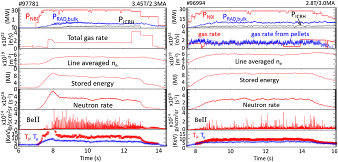
Figure 2. Evolution of best sustained hybrid (pulse 97 781 on the left) and baseline (pulse 96 994 on the right) plasmas, where the bottom plots show Ti and Te at major radius R ≈ 3.22–3.25 m (i.e. at normalised radius ≈ 0.2, there are no CX measurements at the centre). The pedestal temperatures (i.e. at normalised poloidal flux co-ordinates ψN = 0.9) during the steady phase of the pulses are Te,PED = 1.6 keV, Ti,PED = 2.1 keV for 97 781 and Te,PED = 1.35 keV, Ti,PED = 1.7 keV for 96 994.
Download figure:
Standard image High-resolution imageProgress in the baseline scenario (q95 ∼ 3, IP ⩾ 3 MA, βN ⩽ 2.2) relied on the previously established recipe [14] with D pellets for ensuring sufficiently high fELM for W flushing, and low total D2 throughput for good pedestal and core confinement. Compared to plasmas with high gas puffing, these plasmas exhibit higher pedestal Te (Te,PED) but lower ne,PED, along with higher core Ti/Te and rotation [14, 17], with all of these contributing to the improved core transport. The evolution of the baseline shot with best sustained performance is shown in figure 2(b). The W flushing by ELMs and inter-ELM W influxes across the pedestal was quantified in high power baseline plasmas using a method based on a detailed analysis of fast bolometry data [18]. The analysis shows that the pedestal acts to draw W into the confined plasma, but the ELMs are providing sufficient flushing to maintain a steady W content. Furthermore, the flat core ne and peaked Ti, Te profiles of these baseline plasmas result in outward W convection, localising the W to the periphery from where it can be efficiently flushed out by ELMs.
This successful recipe (pellets for ELM pacing and low gas dosing for improved pedestal and core confinement) was extended to 3.8 MA, with a single shot at 4 MA. The highest peak neutron rate in baseline plasmas so far is obtained at 3.5 MA, but more time is needed for optimising the performance at 3.8 MA and 4 MA with PNBI > 30 MW. In contrast to initial results in JET-ILW [19], similar plasma energy to JET with C-wall plasmas are obtained at 3.5 MA, and a clear improvement at 3.8 MA and 4 MA compared to [19], though with higher power to compensate for the fact that gas fuelling for W control leads to stored energy degradation in JET-ILW. Disruption avoidance was an integral part of this scenario development, see section 4.2. During the work to optimise baseline plasmas, a high confinement regime with naturally small ELMs was obtained by reducing gas dosing to zero [20, 21]. Although so far not sustained, this regime highlights physics of interest to ITER: Ti/Te > 1 from the pedestal to the core and (hollow) impurity profile contributing to ITG turbulence stabilisation, and small ELMs at low ν*.
The 'predict first' approach applied to predicting D performance when increasing BT, IP and power, based on integrated theory-based pedestal-core models, using as a starting point the 2014 plasmas, as reported in [22], proved very successful in predicting hybrid and baseline deuterium plasmas fusion performance at higher BT, IP and power. However, it is important to note that the JET-ILW baseline plasmas with pellets show compound ELMs, with pedestal behaviour not well reproduced by the predictive pedestal model used, EUROPED [23]. EUROPED does not calculate self-consistently ne,PED but used empirical assumptions based on the JET pedestal dataset, and assumed Ti,PED = Te,PED as was the case for the 2014 plasmas, while the latest baseline plasmas with highest performance show Ti,PED > Te,PED. Further development of self-consistent, theory based, pedestal models, e.g. such as described in [24], are required in order to predict ITER and fusion reactors performance with higher confidence.
2.2. Radio frequency heating schemes for ITER PFPO and D–T operation
ICRF heating is a key ingredient for core impurity control in JET and can boost the fusion performance by increasing Ti or through NBI-ICRF synergy [25]. In recent experiments with 3He minority heating, the best plasma performance in terms of neutron rate and plasma energy was obtained at low 3He concentration of ∼2%. This supports findings from earlier multi-code predictions for ITER [26] where good absorption and performance with a 3He concentration of ∼3% was found. A lower 3He fraction is desirable as it leads to a lower operational cost. 3He minority heating and 2nd harmonic heating of T, the two main ICRF schemes foreseen for ITER full-field operation in D–T plasmas, will be investigated in the coming JET T and DT campaigns [27].
Significant progress was achieved with three-ion ICRF scenarios, now a flexible tool with a broad range of applications [28]. Recent experiments in mixed D-3He plasmas (n(3He)/ne ≈ 20%–25%) generated fusion-born α in the plasma core at a rate 1–2 × 10¹⁶ s−1 [29], figure 3(a), and demonstrates new fast-ion (FI) diagnostic capabilities for DTE2. Figure 3(b) shows the spatial profile of the D–D neutron emission, inferred from tomographic reconstruction of the measured γ-ray emission with new detectors. These experiments provided insights in the complex interplay between FI effects and plasma confinement. A large variety of Alfvénic eigenmodes (AEs) were frequently observed, including toroidal AEs (TAEs), ellipticity-induced AEs and in some cases reversed-shear AEs. The strong source of electron heating from MeV-range ions also allowed studying plasma transport and the impact of FI on microturbulence in conditions close to those expected in ITER with α heating. In particular, the experimental observation Ti ≈ Te was explained by the detailed gyrokinetic analysis, revealing a novel mechanism of turbulence stabilization in plasmas with MeV-range ions and strong FI driven AEs [30].
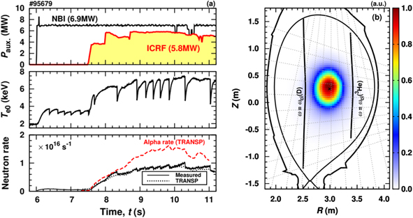
Figure 3. (a) Pulse #95679, with the three-ion D–(DNBI)–3He scenario applied for heating and FI generation. The bottom panel shows the simulated (TRANSP) D–D neutron and D-3He α rates. (b) Spatial profile of D–D neutron emission. Figure reproduced from [29].
Download figure:
Standard image High-resolution imageThree-ion ICRF scenarios are promising for the non-active and D–T operational phases of ITER. An example is the three-ion 4He–(3He)–H ICRF scheme, recently applied for heating non-active H–4He plasmas at JET. In these experiments, for the first time, an enhanced high-resolution sub-divertor residual gas analyser [31], as planned for ITER, provided simultaneous measurements of 4He and 3He concentrations (n(4He)/ne ≈ 10%, n(3He)/ne ≈ 0.2%). The experiments were accompanied by good progress in modelling three-ion ICRF scenarios. The distributions of FI computed by PION [32] and TRANSP/TORIC [5, 6] were validated against a broad range of FI diagnostics [33, 34]. The numerical simulations guided the design of dedicated scenarios to be performed in DTE2. The planned applications include the demonstration of Ti increase with ICRF heating of 9Be impurities relevant for ITER, and optimized fusion-power production scenarios for α physics and AE studies.
2.3. Preparation for α driven TAEs experiments in D–T
Significant progress was made in preparing the dedicated scenario for maximizing the likelihood of observing α-driven TAEs in the JET D–T campaign, as reported in [35]. Enhanced performance compared to past campaigns was obtained, with the highest neutron rate in a NBI-only ITB discharge in JET-ILW to date achieved in pulse 96 852 (2.55 × 10¹⁶ s−1, PNBI = 31 MW), exceeding that previously reported [36], and comparable to the deuterium pulse #40214 in JET with carbon wall (JET-C). That pulse was considered the best candidate for α-driven TAE studies in the first JET D–T campaign. The afterglow phase in #96852 is triggered on neutron roll-over by a RT algorithm designed for this purpose. TRANSP simulations for this pulse assuming D–T plasmas and D–T NBI predict a normalized fusion α pressure βα (0) ∼ 0.13% (figure 4) i.e. significantly larger that the values typical of successful α-driven TAE experiments performed in TFTR [37]. Non-linear stability calculations are underway to predict whether the drive associated to α will be sufficient to overcome the damping mechanisms during the afterglow, to be compared to the experiment in DTE2.

Figure 4. Comparison of JET pulses 92 054, 96 852. (a) Time traces: NBI power, line average density (interferometry), DD neutron rate; Also shown is the neutron rate for reference JET carbon wall pulse 40 214, shifted by −0.31 s (b) TRANSP extrapolation to DT of pulses 92 054 and 96 852: (top) alpha density; (bottom) normalised alpha beta.
Download figure:
Standard image High-resolution imageIn support of AE experiments, the AE active diagnostic successfully excited thousands of stable AEs in hundreds of plasmas during the recent JET D campaign [38]. Measured frequencies, net damping rates, and toroidal mode numbers agree well with MHD, kinetic, and gyrokinetic simulations [39, 40]. Novel measurements of marginal AE stability in plasmas with high power give confidence in successful operation during DTE2, overcoming evidence of limited TAE diagnostic efficiency in H-mode and X-point magnetic configuration [41].
2.4. High performance seeded plasma with ITER relevant edge conditions
The preparation for DTE2 included the development of an integrated, high core performance, neon seeded scenario with 2.7 T/2.5 MA, high triangularity δ = 0.4, and divertor configuration with inner and outer strike-points (S-P) on vertical targets, with edge and divertor conditions closer to those sought for in ITER [42]. In contrast to previous results at lower power [43], Ne seeded plasmas with PNBI ⩾ 25 MW, up to 30 MW, lead to high Te,PED (up to ∼1 keV) and H98(y,2) (up to 0.9). A scan with neon varied shot-to-shot shows that the neutron rate increases with Ne. In the range investigated, type-I ELMs change to small/no ELMs at the highest radiative fractions, with stationary conditions and H98(y,2) ∼ 0.9, βN ∼ 2.2, Greenwald fraction ⟨n⟩/nGW ∼ 0.68 and neutron rate = 1.4 × 10¹⁶ n s−1 until the end of the high power phase (figure 5). In contrast to previous experiments where N2 seeding led to better performance than with Ne, new comparisons at PNBI = 28 MW show that Ne seeded plasmas achieve higher H98(y,2) and neutron rates for the same plasma energy. This is due in part to the higher ne,PED (lower Te,PED) for plasmas with N2. Gyrokinetic modelling is on-going to determine whether core confinement is also improved. The well diagnosed discharges are used for validating physics-based scrape-off layer (SOL)—edge modelling. Fair agreement with the experiment is obtained for divertor target profile and radiation distributions [44, 45], increasing confidence in ITER divertor design basis and strengthening the case for choosing Ne over the chemically reactive N2 for ITER. As reported in the IRP, [65], the tritiated ammonia formed when using nitrogen impacts (1) the cryopumps regeneration requirements and in turn ITER duty cycle, and (2), the ITER tritium plant design, which needs to avoid the formation of deleterious nitrogen oxides.

Figure 5. Shot 97 490 (δ = 0.4, strike-point on divertor vertical targets) with neon (fRAD = 0.68) and high input power. The D2 and neon gas rate during the steady high performance phase are 3.65 × 10²² e s−1 and 2.4 × 10²² e s−1 respectively, and the normalised confinement factor in that period is H98,(y,2) = 0.9.
Download figure:
Standard image High-resolution imageJET integrated seeded scenario will be performed in the coming tritium and D–T campaign—the first time for seeded plasmas—to identify the impact of isotope and mixed species on the divertor and edge plasma, where this is expected to play a role in detachment mechanisms, radiation distribution, divertor compression and power exhaust, and on the pedestal and core confinement.
3. Impact of plasma species and isotope mass
Isotopic effects were observed in DTE1 and impacted progress towards high fusion, e.g. [7, 8, 46, 47]. To better prepare for DTE2 and to provide the physics basis needed to predict ITER, a series of campaigns with different hydrogen isotopes, H (2016 with H-NBI and 2020 with RF-only), D (2019–2020) and T were planned. The experiments are designed with the help of theory-based modelling, to address specific physics questions and disentangle the mechanisms affected by isotope mass in the core, pedestal, SOL and plasma-wall interaction, and to clarify the role of parameters that will differ in ITER (e.g. rotation, divertor conditions). Selected results are reported below. It is worth noting that some results when changing isotope mass could not be reproduced by simplified turbulence models (e.g. quasi-linear approximation) and needed fully non-linear simulations, thus indicating the need for improved reduced models, correctly taking into account the impact of isotope mass.
The results presented in sections 3.1 to 3.5, add to the existing JET results relevant to ITER PFPO H and He operation, and to the physics basis required to refine ITER FPO predictions, taking into account the impact of isotope mass. Several of the results address specific research needs identified by ITER to support the preparation and realisation of the IRP, listed in [171], namely: isotopic effects on H-mode operation (including access power required) and on impurity transport, mixed fuelling species control with pellets, and investigation of power and particle flux in H-mode in H, D, T.
3.1. Core and pedestal transport and confinement
By exploiting the change in isotope mass, A = mi/mp, NBI-heated L-mode and type I ELMy H-mode plasmas at moderate β were obtained in JET-ILW in H and D, with similar profiles of the dimensionless plasma parameters ρ*, ν*, β, q, and similar Zeff, Ti/Te and Mach-number profiles [48]. In the core confinement region the dominant instabilities are ITG modes both in H and D. The dimensionless thermal τE (Ωi τE,th) is identical in the L-mode isotope identity pair, indicating lack of isotope mass dependence of the dimensionless τE,th, and the invariance principle is satisfied in the core confinement region [49]. In the type I ELMy H-mode pair, similarity in H and D is found for both core and pedestal for the ELM-averaged profiles, but not for the pre-ELM profiles. Ωi τE,th is not identical in the H-mode pair and yields an isotope mass dependence Ωi τE,th ∼ A0.51, consistent with the favourable isotope mass scaling of the dimensional τE,th observed in JET-ILW [49, 50]. Predictive flux driven simulations of core plasma transport with JETTO-TGLF (L-mode pair) and TRANSP-TGLF (H-mode pair) are in agreement with the experiment for H and D: the stiff core heat transport, typical of JET-ILW NBI L-modes and NBI H-modes at moderate β, overcomes the local gyro-Bohm (GB) scaling of gradient-driven TGLF, explaining the lack of isotope mass dependence in the core region of the L-mode plasmas and the increase of confinement with isotope mass in the H-mode plasmas, originating in the pedestal region. The effect of E × B shearing from sheared toroidal rotation on the predicted core heat and particle transport channels is negligible in the low β and low momentum input L-mode plasmas, while it becomes apparent in the H-mode identity pair at moderate β.
Observations that the impact of isotope on H-mode plasmas comes mainly from the pedestal [49] motivated recent gyrokinetic (GK) theoretical investigations of JET pedestals showing that the toroidal branch of the ETG instability can be driven at ion-scale poloidal wavelengths and may be responsible for significant inter-ELM pedestal heat transport [51, 52].
In some regimes (high FI content, beta and rotation), isotope effects on core plasma may become important as indicated from predictive modelling [53]. Recent experiments in D2 and H2 L-mode plasmas studied the isotope dependence of ion heat transport by determination of the ion critical gradient and stiffness through varying the IC resonance heating power deposition. Core GK modelling applied to these experiments show that, in plasmas with a strong stabilizing effect of fast particles, differences in fast particle content with isotope mass may lead to strong deviations from the GB scaling of core transport. The difference between H and D is attributed to the differing FI pressure gradient, in turn due to different heating deposition and FI slowing down time [54]. Experiments are being prepared for the tritium and DTE2 campaigns, designed to disentangle the effect of isotope mass and of α on core confinement, and the role of plasma rotation.
Isotope effects on intrinsic rotation was investigated by comparing the rotation of the main ion in H and D discharges. Density scans in H and D were performed for the study of rotation reversals, at 2.7 T and IP = 1.7 MA and 2.3 MA, and at 1 T/0.9 MA to provide a match for a JET-DIII-D similarity experiment. This led to the first clear observation of rotation reversals in a large tokamak. The phenomenology is similar in H and D, however the critical density for reversal and the magnitude of the core rotation depends on isotope, with stronger co-current rotation and larger rotation gradients in H, but with deeper counter-current rotation in D. Linear GK calculations (TGLF [55] and GS2 [56]), show that the low density rotation reversal occurs close to the density of transition from dominant TEM to ITG instabilities, but the sign of rotation shear cannot be associated to a particular type of instability, since peaked rotation profiles can be observed with either ITG or TEM. This work is reported in [57].
Comparison of recently developed ICRH-only H-mode plasmas with mixed ELMs, with low input torque and dominant e-heating, to their NBI-only counterpart at same total power shows similar global confinement and temperature profiles. The ICRH-NBI identity pair have matched dimensionless profiles of q, ρ*, υ*, βn and Ti/Te within 5% except in the plasma core (ρTOR < 0.3). The most significant difference is the ne profile, twice as peaked for the NBI plasma as for the ICRH one. The normalised ne gradient length R/Ln averaged over ρTOR = 0.4–0.8 is R/Ln = 0.93 and R/Ln = 0.45 for the NBI and ICRH case, respectively. The increase in the density peaking by a factor of 2 can be explained solely by NBI fuelling, since, according to GENE and TGLF simulations, the background transport is the same between the ICRH and NBI discharges [58]. This result is consistent with that from a dimensionless collisionality scan in JET H-mode plasma [59], showing the NBI contributing to ∼50% of the fuelling.
Mixed isotope (H-D) experiments [60] were extended to 2.3 MA and 2.3 T to include vertical kicks for the control of fELM and thus ensure similar pedestal conditions. At constant gas and power, the thermal stored energy depends linearly on the effective mass across the probed effective mass (mEFF) from 1.0 to 2.0, in contrast to earlier results at 1.4 MA and 1.7 T [60] which showed a dependence on the mEFF only at the extremes of the scan, i.e. close to full purity of H and D, respectively. Detailed analysis is ongoing to pinpoint the reasons for the differences.
Control of the plasma H:D isotope mix using solely shallow pellets (in H or D) was demonstrated in recent experiments, attaining 50%/50% H/D ratio [61]. The isotope mix propagates to the core on the energy confinement timescale, in agreement with quasilinear theory as reported in [62] where it is shown that the combination of stabilisation by R/Ln and destabilisation by R/LT leads to ITG drive and thus to fast isotope mixing following each pellet injection throughout the pellet train. Analysis of the dataset for different pellet sizes, content and plasma current, and including for the first time pellets with ITER-like ablation and relative pellet size, indicate high efficiency for pellets with ablation depth r/a < 0.95, but falling sharply for shallower pellets.
3.2. L–H transition
A variety of studies of the low to high confinement transition (L–H) have been undertaken at JET since the installation of the ILW. They are summarised in [167]. Here we highlight the recent results in helium plasmas, compared to protium and deuterium plasmas.
It is desirable to investigate H-modes in H and He plasmas to validate expectations for the ITER PFPO. Assuming that edge ion heating plays a key role on the L–H transition triggering [63], the ITER team concluded that the electron density at which the L–H transition power threshold is minimum, ne,min, is about 0.4 × nGW. Combining this with the JET-C result that PL–H(He) = 1.4 × PL–H(D) [64], the ITER team produced estimates of the minimum PL–H to be expected in ITER for various 1.8 T plasmas, all at the same density [65].
New L–H transition studies in the JET-ILW allow a comparison of L–H power thresholds for H, D and He for plasmas with 1.8 T, 1.7 MA, in a horizontal target (HT) configuration. The new experiments show a clear shift in ne,min. In terms of the Greenwald fraction (fGW), ne,min(D) ≈ 0.4 × fGW, while ne,min(H) ≈ 0.5 × fGW, and ne,min(He) ≈ 0.6 × fGW. As seen in [167] the shift in ne,min for different plasma species is clearer when plotted in terms of the loss power PLOSS = POHM + PAUX − dW/dt, where POHM is the ohmic power, PAUX is the auxiliary heating power and W is the plasma energy. However, it is also observed when plotted in terms of the power across the separatrix, PSEP = PLOSS − PRAD,Bulk, where PRAD,bulk is the power radiated from the main plasma. In terms of the power threshold itself, for the so-called high density branch (ne > ne,min), PSEP(4He) = PSEP(D) is found. Thus the increase in the predicted PSEP for ITER due to higher ne,min could be compensated by the lower power required to access it, no longer 1.4 × PL–H(D). This would be the case provided radiation is not dominant in helium plasmas in ITER, as it is in JET-ILW.
The formation of the edge transport barrier in a 4He plasma has been investigated with the four-field drift-fluid model HESEL [66, 67]. Experimental profiles from a helium pre-transition state were used. The edge ion temperature is raised artificially to obtain a transition to an H-mode-like confinement with significantly reduced turbulent heat transport across the last closed flux surface. The transition in He is more gradual than in D, because neo-classical transport in helium is comparable to the turbulent transport level.
For the plasmas at higher magnetic fields, Doppler reflectometry allows us to study the evolution of v⊥ shear (related to the radial electric field (Er) shear) along the power ramp [68]. It is found that no significant increase of v⊥ shear is observed preceding the L–H transition. Instead, the contribution of the diamagnetic velocity to the radial electric field increases by up to a factor of 2 along the power ramp. This suggests that the mean Er may well not be the critical variable determining the L–H transition. Detailed investigation of the dynamics of these transient H-modes is underway, and further experiments are planned.
3.3. Plasma edge and divertor
Dedicated experiments in combination with an extended database of unseeded low δ discharges spanning 1.5 < IP < 3.4 MA, 10 < PNBI < 25, 2 < PICRH < 5 MW with q95 = 3–3.4 have demonstrated the importance of the divertor outer target electron temperature (Te,ot) as a key parameter linking the recycling particle source and detachment to plasma performance. In particular, changes in global and edge plasma parameters (H98(y,2), ν*, ne peaking and separatrix ne (ne,sep)) with variations in D2 fueling rate and divertor configuration are condensed into a single trend when mapped to Te,ot as shown in figure 6. This is attributed to the relationship between Te,ot and ne,sep, which for the database can be recovered quantitatively using the SOL 2-point model (2PM) [69], and crucially depends on estimates of the volumetric loss factors capturing pressure-momentum and plasma cooling losses in the SOL-divertor [70]. The increase in edge plasma collisionality associated with increasing ne,sep is correlated with reduced Te,ped and Te,0 via profile stiffness, as well as a decrease in the core ne peaking, leading to a reduction in the core pressure and confinement, consistent with previous collisionality scans of low δ H-mode JET-ILW plasmas [71]. Additionally, a favourable pe,ped scaling with IP is shown in accessing high-recycling (low Te,ot) conditions leading to an increase in pe,ped with D2 fuelling at high IP, although this is evidently not sufficient to lead to H98(y,2) recovery. Further investigations into the role of edge plasma neutral opacity on the pedestal structure are ongoing, with a focus on quantifying the confined plasma fuelling contributions from recycling sources in the main-chamber and divertor.

Figure 6. Database of unseeded discharges showing the range of variation in the D2 fuelling rate ΓD2 and the averaged outer target electron temperature ⟨Te,ot⟩ and correlations with ne,sep Ip −0.5, H98(y,2), density peaking factor ne,0/⟨ne⟩ and pe,ped normalized by pe,ped at ⟨Te,ot⟩ = 25 eV. Marker colour denotes IP with 1.5 MA (blue), 2.0 MA (grey) and 3.4 MA (red). The database includes divertor configurations with the strike point locations on the inner-vertical, outer-HTs, VH(C) and VH(D) with C and D denoting the position of the outer strike point on stack C and D of tile 5; inner and outer vertical (VV) and inner and outer corner (CC). Reproduced from [70].
Download figure:
Standard image High-resolution image3.4. W and Be erosion, transport and screening
JET-ILW provides the most relevant environment for studying Be and W erosion and transport and their implications for ITER operation, plasma-facing components lifetime and T retention by co-deposition. Recent experiments focused on investigating the impact of different hydrogen isotopes on physical sputtering of Be and W, as well as of molecular release (BeH, BeD, BeT) through chemically assisted physical sputtering (CAPS). Full suppression of CAPS at the Be bulk limiters was observed in dedicated experiments in H and D in a similar range of surface temperature of ∼450 °C, complementing earlier D experiments [72], with an improved set of diagnostics including 2D cameras with narrowband interference filters (incl. BeI and BeII) for characterising Be erosion and transport and validating plasma backgrounds used as input in PWI codes like ERO2.0 [73]. Correlation between suppression of CAPS (BeD/BeH) and D/H outgassing is clearly demonstrated and confirms predictions [74]. ERO2.0, which includes a detailed 3D surface model of JET first wall and divertor components [75], was recently improved [76] with multiple diagnostic sightlines of first wall areas where peak erosion measured, or that are shadowed, for validation using localised wall erosion results and the local Be plasma content.
An overview of W gross and net erosion rates at the bulk W outer divertor target plate and high local redeposition of 95% is given in [77] by comparing optical emission spectroscopy and post-mortem analysis and separating inter- and intra-ELM phases. ERO modelling for the inner and outer divertor W erosion helped disentangle the local re-deposition in the inter/intra-ELM phases and the loss paths of W escaping in the confined plasma and SOL [78]. Intra-ELM W gross erosion, which dominates the total W source, were quantified in the inner and outer divertor in dedicated D experiments in three different divertor configuration in ELMy H-mode plasmas [79]. The quantity of sputtered W atoms per ELM depends on fELM, confirming earlier studies [80], with eroded W atoms s−1 increasing with fELM to a maximum at 50–55 Hz, and decreasing at higher fELM. At low fELM (∼35 Hz), the outer divertor W source is larger by ∼1.5 compared to the inner divertor, but the in/out asymmetry decreases with fELM and is nearly symmetrical for >70 Hz. Divertor screening of W in the more open magnetic configuration (S-P on the horizontal divertor plates) is ∼1.7 higher than that with S-P at the far corner, near the pumping duct entrance. Modelling of W transport in JET SOL with EDGE2D-EIRENE and DIVIMP [81] shows that accurate predictions of W density needs a good match to the experimental pedestal and SOL, and that incidence angle, surface roughness, material mix, and W prompt re-deposition must be taken into account to reproduce the measured W I, W II emission. The modelling suggests that sputtering by energetic CX fuel atoms near the top of the outer vertical divertor (where divertor screening does not apply) could contribute significantly to the W influx in the confined plasma in L-mode and inter-ELM phases.
3.5. First tritium plasmas results
The first part of the full T campaign (ohmic or with ICRH), i.e. first experiments with high tritium concentration since 1997, took place at the end of 2020. Results included confirmation that the hybrid plasma current ramp-up and q-profile is impacted by isotope mass as shown in recent H-D experiments reported in [82]. The higher W sputtering and improved transport in T plasmas with same engineering parameters as their D counterparts leads to hollow electron temperature profile thus modifying the q-profile shape and evolution. The optimal q-profile at the end of the IP ramp-up can be recovered in tritium by adjusting the gas and density waveforms, as predicted based on empirical extrapolation and modelling. Other experiments included the investigation of W source and of L–H transition in tritium compared to D and H, with analysis on-going. The dedicated tritium campaign continues in 2021 with tritium-NBI, with a broad range of experiments to study the impact of isotope mass and to complete the integrated scenario preparation for DTE2.
4. Disruption mitigation and avoidance
A crucial part of ITER's strategy for successful operation consists in its disruption mitigation system (DMS), based on shattered pellet injection. As presented in [168] the system's design is now in an advanced state and benefited from recent experiments on several tokamaks with complementary physical characteristics and capabilities. JET provides a unique contribution to ITER DMS preparation thanks to its size, plasma energy and current, as well as its first wall materials and the recently installed SPI. Specific contributions are described in 4.1. JET also provides a database and control schemes experience that are of interest to other aspects of the ITER disruption management described in the ITER Research Plan [65] such as disruption prediction and avoidance, detection of, and response to, unplanned plant events ('exception handling'), and RT schemes for safe plasma termination. Recent examples are described in section 4.2.
4.1. Disruption and runaway electrons studies with JET shattered pellet injection (SPI) in support of ITER disruption mitigation system (DMS)
JET combined characteristics make its contribution to ITER DMS unique and complementary to that of smaller tokamaks. In particular, the characteristic time of key processes determining the plasma behaviour during disruption and mitigation (e.g. destabilisation of MHD modes, thermal quench) scales with machine size, and the pellet relative penetration depth, important for determining the optimum pellet timing and size, varies inversely with the major radius. Additionally, thanks to the ILW, the absence of carbon as intrinsic impurity makes JET well placed to investigate SPI with low impurity content. Thus JET results help to narrow down the requirements for ITER DMS and to validate models used for predicting ITER disruptions, RE and SPI operation. The JET SPI was successfully commissioned and exploited in an extensive set of experiments on disruption and RE avoidance in 2019–2020, with the JET SPI demonstrating good reliability. This work is done in an international collaboration between ITER organization, US DOE, EUROfusion and JET operator. Main characteristics of the JET SPI system include a three-barrel injector capable of delivering Ne, D, Ar and mixed pellets, and the possibility to vary the fired pellet velocity, and correspondingly the shards size and speed [2, 3] with the unique feature of a vertical SPI mounting and injection with shatter plume aimed toward the plasma. Key diagnostics for these studies included fast cameras (with various filters) observing different octants (see figure 7 for example).
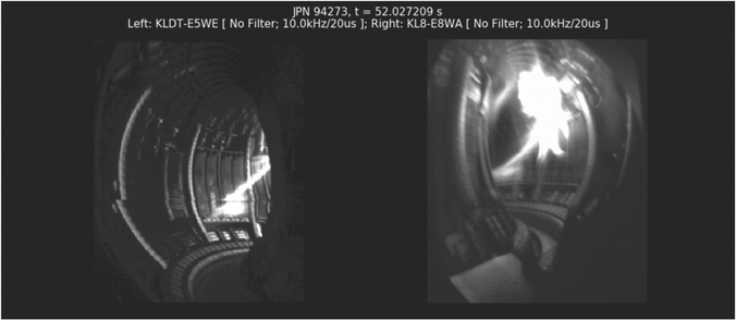
Figure 7. D2 SPI injection (from top right) in JET captured by highspeed visible light camera.
Download figure:
Standard image High-resolution imageThe JET SPI experiments results are presented in [83]. A first set of experiments demonstrated reduction of the thermal load, with complementary experiments with SPI injection into 3 MA/7 MJ H-mode plasmas providing a unique dataset for ITER in terms of magnetic and thermal energy [84]. By varying the neon content in the SPI pellets, the disruption current quench time can be controlled efficiently in JET, covering the range required by ITER. The pellet integrity and size has only a minor impact on the current quench duration.
RE suppression with high Z impurity SPI was also demonstrated. It was found that D2 SPI applied to a high current run-away beam formed by Ar massive gas injection leads to benign impacts on the wall compared to neon/argon SPI, suggesting a potential new solution for RE control in ITER [85] and figure 8. Further RE studies investigated the efficiency of RE dissipation in these conditions. In particular, the trigger of the final instability was characterized with a q-scan at constant IP (1.5 MA), showing that q = 2 is not a necessary condition for the harmless collapse of the RE beam. RE beams of up to 1.5 MA could be safely terminated by sustaining the beam for more than 2.6 s and with controlled IP ramp-down, thanks to the D2 SPI. This was also shown for the ITER relevant scenario of a vertically moving beam [86].

Figure 8. (a) Total current. (b) Average electron density. (c) Total neutron rate. (d) Total radiated power. (e) Heat flux on the first wall following RE impact, for three different RE beam termination scenarios. The vertical dashed line across the top four graphs is the SPI trigger time. Reproduced from [85].
Download figure:
Standard image High-resolution imageThe models required to interpret JET SPI experiments and predict ITER continue to be improved. Recently the thermal energy balance analysis was greatly enhanced, with forward modelling accounting for 3D helical structures (Emis3D) [87]. Modelling with KPRAD [88] accurately reproduced the cooling times measured and the current quench duration at high thermal energies. Simulations of JET SPI with 3D MHD codes JOREK [89, 90] and with M3DC1 [91] are on-going, with recent JOREK results qualitatively reproducing the radiation pattern before the thermal quench [92]. JOREK predictions show that injection from toroidally opposite locations could mitigate asymmetric radiation behaviour observed during single SPI injection [93].
4.2. Disruption avoidance during scenario development
Disruptions in JET carry a risk of significant damage to components and can impact the machine lifetime. Disruption avoidance based on improved termination techniques and RT detection of unhealthy plasmas with jump to controlled termination was a necessary and intrinsic part of the scenario development for DTE2 [94]. This reduced significantly the disruption rate in hybrid plasmas (down to 5% for plasmas >2.0 MA) and contributed in the 3 MA baseline plasma to a reduction from 60% in 2015–2016 to 20% at the end of the 2020 campaign. However, the disruption rate of baseline plasmas ⩾3.5 MA increased from 33% up to 70%. Most of the disruptions take place at lower IP than during flat top, i.e. during ramp down. The reasons are under investigation. Recently developed tools were tested in RT to respond to two main causes for disruption: (1) core W accumulation which can lead to hollow Te profiles, developing relatively slowly towards disruption, (2) poloidally asymmetric radiating blob building up on the outboard side and increasing in intensity until disruption. How these lead to disruption is now well understood [95]. Detecting hollow Te can be done with ECE or soft X rays and both are used routinely but, for the latter, care needs to be taken to separate outer blob from core accumulation. Recently a method of inverting bolometric data in real time has been developed [96] and implemented, which allows the radiation in particular regions of interest to be calculated and used with a simple threshold on either the radiated power in the region of interest, or else on its value normalised to input power, to trigger different responses to core and edge radiation. Typical responses consist in increasing the H concentration since this favours ICRF core electron heating, or controlling the input power relative to the H-mode threshold calculated in RT.
5. Preparation for tritium and D–T operations
The preparation for operations with tritium and D–T involved several plants and diagnostics refurbishments and enhancements over several years, as well as the preparation of improved procedures for safe operation with tritium [97]. These activities are generating valuable know-how of the operation of a nuclear tokamak in the European fusion community that will be useful for fusion power plants design, operation, tritium inventory and waste management, and for their related safety and regulatory requirements. Progress of this work was reported in [97, 172] and references therein. sections 5.1 to 5.5 report only the final steps of the preparation and commissioning for T and D–T operation.
5.1. Tritium neutral beams optimisation
The JET tritium and deuterium–tritium campaigns rely on very high power tritium neutral beam injection (NBI) in order to achieve their scientific objectives. NBI commissioning in tritium was aimed at reliable operation with maximum power and as little gas usage as possible. The system has been optimised in terms of beam perveance and neutralisation efficiency and the resulting beam species mix measured.
Preparation for operation with tritium is complicated by the need to supply tritium to the injectors at ground potential, so as to be compatible with double containment of the feed lines. In JET, this is achieved by feeding tritium at the position of the Earth grid in the injector rather than having separate feed points in the ion source and the neutraliser cell, as is used in normal deuterium and protium operation. Tests of 'grid gas feed' in deuterium showed positive results already in 2019 with the same power achieved as with 'normal feed'. This has now been repeated with tritium and the optimum gas flow rate determined experimentally. As an operational bonus, the optimum gas flow rate in tritium is about 30 mbar-l s, considerably smaller than the 40–42 mbar−l s used for deuterium beams.
A benefit of operating the beams in tritium, due to the lower particle velocity at higher mass, is that the beam neutralisation efficiency does not decrease strongly as the maximum beam voltage (and therefore power) is approached (figure 9). This means that the tritium beams will be able to operate at power levels at or above those already achieved in deuterium.

Figure 9. Neutral beam power of a JET positive ion neutral injector (PINI) when operated in deuterium (black dashed line) or tritium at either optimum perveance (blue full line) or increased perveance (red full line).
Download figure:
Standard image High-resolution image5.2. Tritium processing plant
The tritium and deuterium–tritium experiments planned for 2021 require a significant increase in the capability of the tritium plant—the active gas handling system (AGHS [98, 99])—as compared to the JET DTE1 experiments in 1997. Whereas in DTE1, T was supplied to one neutral injection box (NIB) and one dedicated gas injection module, the present experiments will at various times use T from both NIBs and from five new, high-flow T injection modules. Overall, it is expected that about 1000 g of T will be supplied to JET, recycling an on-site inventory of 70 g. This is compared to an inventory of 20 g during DTE1 and total fueling of 100 g. By February 2021, AGHS had already supplied more T to JET than was supplied in the entirety of DTE1. AGHS consists of 12 interconnected subsystems, which feed, recover and reprocess tritium in a batch process (figure 10). To keep up with the experimental schedule, AGHS must operate 24 h a day, 7 days a week. The limiting factor for tritium throughput rate is isotope separated by the gas chromatography (GC) subsystem, which is capable of processing up to 90 bar-l of hydrogen per day. Not having been used for operations since the Trace Tritium Experiment in 2003, AGHS required extensive recommissioning and enhancement. In addition, a major failure of the exhaust detritiation system (EDS) in 2017 required its complete replacement. Procuring, installing and commissioning the new EDS set the critical path for meeting the ready for tritium operation operator milestone. The milestone, which included active recommissioning of all subsystems once EDS was again available, was met on September 4, 2020.
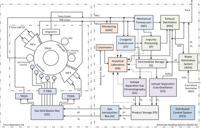
Figure 10. Schematic of JET's AGHS.
Download figure:
Standard image High-resolution image5.3. Core charge exchange enhancement and final neutron calibrations
CX spectroscopy of the fuel ions provides a complementary measurement to impurity spectroscopy. Both are complex measurements and face challenges in high density plasmas where beam attenuation is significant. The low levels of intrinsic C together with multiple interfering W lines [100, 101] in JET-ILW mean that seeding of the plasma with trace levels of Ne is required for impurity measurements. On the other hand, the strong intrinsic emission of edge Balmer-alpha light and the overlapping Stark spectral features from multiple injectors on JET means that beam modulation is needed for the fuel-ion measurement. The upgrade project (2016 shutdown) installed two pairs of spectrometers sharing the same lines-of-sight with a dichroic mirror splitting the light to the two instruments at 600 nm, allowing simultaneous measurements of impurity and hydrogen CX from the same active volume [102]. The improved capability allows the plasma and impurity parameters to be compared, taking into account features such as fine-structure splitting in the impurity spectra and demonstrating good agreement between the two measurement techniques, with no significant neoclassical temperature differences [103].
As part of a major upgrade of JET's neutron and gamma diagnostics, a calibration of the measured 14 MeV neutron yield has been carried out using both a neutron generator deployed on JET's in-vessel remote maintenance system [104, 105] and, more recently, short puffs of T into D plasmas. Historically, 14 MeV neutron production has been measured on JET using a system of silicon diode and diamond detectors [106, 107]. The silicon diode detectors degrade under neutron irradiation and require regular replacement. For DTE2, expected to produce record levels of neutron generation, two new silicon detectors and four single crystal diamond detectors have been installed, providing resilient, radiation hard 14 MeV neutron monitoring over a large dynamic yield range. The recent plasma calibration was aimed at cross-calibrating the monitoring fission chambers, the newly installed silicon/diamond detectors and the JET's activation system, which provides absolutely calibrated measurements of pulse-integrated neutron yield. Excellent correlations have been measured between the different 14 MeV detectors (figure 11). The absolute yield has been determined from the Al(n, α) and Fe(n, p) dosimetry reactions and calibrations applied to the detectors in time for the beginning of JET's tritium campaign.

Figure 11. Correlation between the 14 MeV neutron signal from one of the new diamond detectors and measurements from one of the silicon diode detectors and measurements from the activation system.
Download figure:
Standard image High-resolution image5.4. D–T rehearsal
Experiments with tritium are subject to a range of additional boundary conditions and requirements. Programmatically, the most important of these are the overall 14 MeV neutron budget of 1.55 × 10²¹ and the safety case limitation that no more than 44 bar-l of tritium may be accumulated on the torus and NIB cryogenic pumps. Experiments thus must make optimum use of the machine time available. Planned T and DT discharges have been rehearsed in deuterium or protium plasmas so that development in tritium is minimised and ideally limited to exploring the differences introduced by the tritium itself or alpha particle effects. Experiment planning and approval has also been tightened with individual pulses requiring approval rather than campaign sessions.
A series of rehearsals of the operational and programmatic procedures for use in tritium have been carried out (without the use of tritium). The first, in 2016 [108], was largely technical. High power NBI operation with tritium-compatible fuelling was demonstrated and the commissioning of various safety systems was started. A subsequent rehearsal in 2020 included also rehearsing the procedures for performing experiments with tritium. The high-level objectives for this second rehearsal are given in table 1.
Table 1. Planned high-level rehearsal actions. Due to a coil coolant leak, the final week of the rehearsal was cancelled but the main DT rehearsal goals were achieved.
| DT rehearsal | 7/9/20–11/4/20 | 14/9/20–18/09/20 | 21/9/20–25/9/20 |
|---|---|---|---|
| DT safety case | Ready | ||
| J1T depression/depletion test | Combined 5 days | Combined 3 days test | |
| J1 access | 3 days | 3 days | 3 days |
| Daily full regeneration of all cryos | With CF | With CF | |
| Reference pulses/44 bar.l limit | 3 days | 3 days | 3 days |
| Experiment preparation | Yes | ||
| Experiment planning | Yes | ||
| Intershot data analysis | Yes | ||
| Control room procedures | Yes | ||
| Diagnostic rehearsal | 3 days | 3 days | 3 days |
| Site-wide emergency exercise | Various, up to 1 shift | ||
| Maintenance | 3 days | 3 days | 3 days |
A lessons-learnt exercise was carried out after the rehearsal, with 152 issues raised. The issues were then rationalised, categorised, and prioritised. Sixty issues were judged to require no further action (these included duplicate issues and issues addressed immediately after the rehearsal). The remaining 92 issues were then actioned. All the DT rehearsal actions were completed by June 2021.
5.5. Wall cleaning and isotopic and plasma species content monitoring
A strategy to remove D from PFCs was successfully tested prior to the T campaign and brought the plasma isotopic ratio D/[H + D + T] below the 1% target set by the T campaign 14 MeV neutrons budget, reported in [109]. It consisted of main chamber baking under vacuum at 320 °C, followed by isotopic exchange with ion cyclotron wall cleaning (ICWC) and glow discharges (GDC) in H2 at that temperature. Diverted plasmas with PICRH = 5 MW lasting 20 s were then operated in different magnetic configurations with the main chamber at 200 °C, targeting the inner divertor baffle region. ∼9 × 10²³ D2 were removed from JET PFCs, as determined by gas chromatography, mass spectrometry and optical Penning gauges, of which ∼54% by baking and 41% by ICWC and GDC, and the rest by plasma cleaning. A similar sequence will be used after DTE2 with D plasmas aiming to reduce the exhaust T to <1%, providing an assessment of the tools foreseen for T removal or mitigation of inventory build-up in ITER.
Plasma pulse-resolving exhaust gas analysis, including Penning optical spectroscopy, was recently upgraded to assure achieving this detection limit capability and maintaining it through DTE2 [169, 170]. Complementing this capability and that of the edge spectroscopy, the plasma core isotopic ratio can be inferred from neutrons diagnostics when including the measured profiles and FI calculations [110]. A workflow using new tools such as ASCOT [111, 112] coupled to JETPEAK [113, 114] with a new interface provides daily analysis and trends of isotope content, as well as fast D–T predictions and EP analysis to guide experiments.
6. Plasma facing components (PCF) after long term exposure in JET with ILW
Regular retrieval of plasma-facing components (PFC), erosion-deposition probes (EDP) and dust particles performed during shutdowns after each of the three ILW campaigns has provided representative set of specimens for ex-situ studies and—as a consequence—allowed for a deep insight into material migration including fuel retention and dust generation. This comprised research on tiles from the poloidal cross-section of the divertor, both W-coated (tiles 0; 1; 3; 4; 6–8) and bulk tungsten tile 5 as well as all major categories of limiters: inner wall guard (IWGL), outer poloidal (OPL) and upper dump plates (UDP). In addition, several types of studies have been performed for the first-time ever in connection with a clear interest and direct request from ITER: metallography and mechanical analyses of Be and W tiles, and also assessment of dust and tritium accumulation on the equipment for remote handling (RH). The overall aims were: (i) to obtain a comprehensive erosion-deposition pattern before the planned D–T campaign; (ii) to provide basis for the best-possible predictions for ITER regarding the melt damage of bulk Be and W tiles, tritium inventory and the modification of diagnostic test components.
6.1. Material migration and fuel retention
Figure 12(a) shows a castellated beryllium limiter from the inner wall, while in figure 12(b) there are deuterium deposition profiles on the IWGL determined after three single campaigns (ILW-1 in 2011–2012, ILW-2 in 2013–2014, ILW-3 in 2015–2016) and a profile on the tile exposed during all of them [115, 116]. There are some common features. Qualitatively and quantitatively all profiles are of the same character indicating: (i) the erosion zone in the central part of the limiters where the content of D atoms does not exceed 0.1 × 1018 cm−2; (ii) deposition zones at the curved sides with the D concentration reaching maximum of 1.4 × 1018 cm−2. Even those highest values of inventory are very low both in absolute and relative terms when either extrapolated to tritium retention in 1:1 D–T operation (35 mg T m−2) or compared to JET-C where fuel content in some areas was over two orders of magnitude greater than in JET-ILW [117, 118].
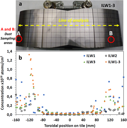
Figure 12. (a) Castellated beryllium mid-plane IWGL tile after exposure during all three ILW campaigns, areas of the co-deposit and dust sampling are marked; (b) deuterium areal concentrations at mid-plane measured after consecutive campaigns and after all three campaigns ILW1-3; data for ILW-1 and ILW2. Figure 1(b) Reproduced from 117].
Download figure:
Standard image High-resolution imageMicroscopy images and x-ray spectra in figures 13(a)–(d) show features of the co-deposits and dust from the deposition zones on the limiter, in spots A and B marked with circles. These are the first results for co-deposits sampled directly from the Be limiters. The sampling with sticky pads resulted in the isolation of only tiny quantities of the co-deposit (low μg range) thus indicating good layer adherence to the Be substrate. This confirms earlier results from visual inspections of the tiles. The layers are not uniform in terms of structure (granular in figures 13(a) and stratified in figure 13(c)) and composition with the presence of Be, C, N, O and metals such as Ni and W. Figure 13(c) shows splitting of the strata leading to the increased porosity of the layers. There are also places containing a mesh-like Be–Ni structure clearly visible in the backscattered electron image, figures 13(d) and (e).

Figure 13. Surface structure and composition of co-deposits on the beryllium IWG limiter after all three ILW campaigns. Sampling areas A and B are marked in Figure 12. Figures 13(e) is reproduced from [171].
Download figure:
Standard image High-resolution imageThe deposition of D, Be and C on the divertor tiles in the three ILW campaigns is shown in figure 14, with corresponding distribution of strike point location and duration in a given position [122]. In all three campaigns, the patterns are very similar with most deposition on the inner divertor tiles 0 and 1 [119–127].
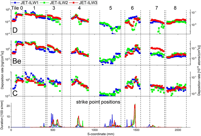
Figure 14. Top to bottom: distributions of deuterium, beryllium and carbon deposition rates (in logarithmic scale), and distribution of strike point positions (linear scale) in the first three JET-ILW campaigns. Vertical dashed lines indicate borders of the divertor tiles. Black numbers on top of the figure identify tile analysed, see figure 15 for divertor tile location. For tile 5, data are shown for the lamellae in stack C, row 13. Reproduced from [124].
Download figure:
Standard image High-resolution image
Figure 15. JET-ILW divertor, with divertor tiles and location identified by numbers 0 to 8. The separatrix for a plasma configuration with inner and outer strike-points on tile 4 and 6 respectively is shown in blue. Tile 5 is composed of 4 'stacks' identified as A to D from left to right.
Download figure:
Standard image High-resolution imageSome differences are related to the strike point positions, especially in the last phase of the operation in respective campaigns. For ILW-2 and ILW-3, when strike point positions were often on tiles 4 and 6, the D content on that region is lower in comparison to that in ILW1, likely due to higher peak surface temperature of the tiles during those campaigns. In areas of high temperature (T ∼ 1400 K) [128] almost no deuterium has been found. Other species detected in the analysed layers are mainly on tiles 0 and 1 are: nitrogen from N2 puffing and oxygen connected partly with in-vessel impurities and Be oxidation when exposed tiles were in contact with atmospheric air. The most important is a significant reduction, by a factor of 2, of carbon deposition from campaign-to-campaign both in terms of the absolute amount and accumulation rates. The relatively high C content in ILW-1 could be attributed to the residual carbon impurities remaining from JET-C and surface contaminants on the W-coated tiles. In summary, all data confirm earlier results regarding reduced material deposition and retention of hydrogen isotopes in comparison to JET-C. This also clearly indicates that W coatings on the ILW divertor tiles were not seriously damaged and, therefore, plasma was not in contact with the carbon substrates.
The deposition localized in the upper part of inner divertor is in contrast to results observed in JET-C, where co-deposits were formed mainly on shadowed parts of tiles 4 and 6 [117]. This is due to different erosion mechanisms of Be and C by hydrogen atoms and—in a consequence—differences in transport of eroded species through the divertor. Carbon has a high chemical erosion rate and could be transported in a multistep process towards shadowed regions in the divertor, while Be erosion rate by D is lower as the element is not susceptible to purely chemical erosion processes [72]. As a result, eroded Be atoms mostly remain in the area where they were first re-deposited from the SOL. However, despite that fact, some quantities of beryllium reach shadowed regions in the divertor, as detected in studies of wall probes located in the divertor: test mirrors and [129–131], spatial blocks [132], rotating collectors [133–135], louvre clips [136] and covers of quartz microbalance [121, 132].
6.2. Material modification by heat loads
6.2.1. Investigation of damaged beryllium upper dump plates (UDP)
Beryllium melting and splashing from UDP was examined with emphasis on the identification of factors triggering this process [137]. High-resolution images have documented flash melting on the ridge of the roof-shaped tiles, as documented in figure 16(a). The melt layers moved in the poloidal direction towards the outboard tiles. At the end of the last tile (UDP-8) the molten matter moved upwards forming a flake of a waterfall-like melt structure. The general appearance and details of that structure are shown in figures 16(b)–(e). In close-up images of the top surface, one perceives numerous Be droplets ranging in size (diameter) from micro-to millimetres. Detailed imaging provides a clear evidence of multiple melting and cooling cycles responsible for the layered sub-structure of the flake (figures 16(c) and (d)). There are a few main strata ranging from 60 μm to 500 μm in thickness, thus clearly indicating the link to several high-power events. Further structural details are in the electron microscopy image, figure 16(e). During three ILW campaigns around 15% of all 12 376 plasma pulses were catalogued as disruptions. The undisputed reason for melting were unmitigated disruption events which tend to move the melt layers in the poloidal direction resulting in the formation of upwards going waterfall-like structures of molten metal. The halo current is believed to provide the j × B force driving the melt layer motion. The total material losses from all dump plates were estimated at the level of 129 g during ILW2 and 55 g in ILW3. The estimation was based on: (i) precision weighing of some retrieved tiles and (ii) computer-assisted analysis of high-resolution images documenting splashes on the upper walls. It is stressed that splashed beryllium droplets adhere well to surfaces where it was deposited thus not contributing to dust formation dust in ILW. This is consistent with a very low dust inventory: approximately 1 g per ILW campaign with 19–23 h of plasma operation [120, 138, 139]. In addition, no mobilization of Be dust was caused by remotely handled (RH) equipment operated during the shut-down period [140].

Figure 16. (a) Melt damage across poloidal direction on the upper dump plate (UDP-8), with a close-up on the waterfall-like structure of the flake in (b); cracked (c) and stratified (d) flake structure with details electron micrograph (e).
Download figure:
Standard image High-resolution imageMorphological analyses of the molten material revealed the presence of Be and BeO with some heavy metal impurities: Ni, Fe, W. Deuterium concentration in the melt zone of UDP-8 was determined by means of ion beam analysis both in toroidal and poloidal direction: 1.1–2.1 × 1017 cm−2. Slightly increased amount of 3.0–4.0 × 1017 cm−2 was in the areas less affected by melting phenomena. The high surface temperature during melting is likely to result in the release of trapped D thus explaining the variation between melted and non-melted areas. Similar results were seen on the Be waterfall structure on both front and bottom sides, with D concentrations in the range 1.1–6.3 × 1017 cm−2. In summary, the results clearly show low fuel content on the upper dump plate and Be waterfall-like structure which comprise both the non-damaged surfaces and the re-solidified ones, with no excessive trapping of fuel in the melt zone.
Modelling of Be melting under fast transient events with MEMOS-U [141] indicate it can reproduce the key physical processes involved. Qualitative agreement with ex-situ findings from dust collection and Be deposition pattern near the UDP is obtained with DUSTRACT [142–144].
6.2.2. Divertor bulk tungsten tiles
Bulk tungsten tile (tile 5) in the divertor base is composed of four stacks (A-D) each containing 24 rows of lamellae. Thermal loading to respective stacks and lamellae within a stack is not uniform. Elements 1–5 are shadowed by the adjacent tile, while loading increases towards the other end of the tile with the greatest load on lamellae from rows 23 and 24. Comparative studies were performed on elements of stack C (row 14 and 23; notation C14, C23) with the longest time of strike point location and, on stack A (row 14, notation A14) with no strike point location, as shown in figure 14. Lamellae after ILW-1 and ILW-2 were examined to determine the surface topography, metallography and mechanical properties [139]. These bulk tungsten components are produced using electro-discharge machining (EDM) without subsequent surface treatment. As a result, the surface is characterized from the beginning by a micro-crack network with a crack depth of up to ∼50 μm and average roughness Ra of ∼2 μm. Micrographs of surface topography and cross section of the lamellae from stack A, and from the middle part of stack C (row 14) have proven that thermal loading applied during ILW-1 had no clearly measurable or visible effect on the surface roughness and the micro-crack network, as shown in figures 17(a) and (b) for a piece from stack C, row 14. Differences in surface and bulk features become evident with the increased power loads, as documented for piece C23, figures 17(c) and (d). One perceives that under high power loading a shallow surface melting and melt motion occurred [145, 146] and, as a result, the average surface roughness has been decreased by 30% from 2.2 μm for C14 to 1.4 μm for C23 [145]. Below this slightly smoothened surface an increase in the crack depth up to ∼150 μm is observed. However, on a positive side it can be stated that irrespective of these changes, no modification of the materials microstructure, in particular due to recrystallization-induced grain growth, has occurred. Hardness measurements have shown higher values in the near-surface region (∼100 μm) when compared to the bulk by ∼25 HV1 (ILW-1) and ∼10 HV1 (ILW-2). This may indicate that the plasma influence on that material is associated rather with the diffusion of species arriving to the surface (mostly hydrogen isotopes) than with thermal effects. This is a tentative statement and the issue needs further detailed investigation.

Figure 17. Microscopy images and metallographic cross sections of the lamellae C14 and C23. Reproduced from [145].
Download figure:
Standard image High-resolution image6.2.3. First mirrors tests for ITER
Optical plasma diagnostics and imaging systems in ITER will rely on metallic so-called first mirrors. Therefore, on the instigation of the ITER Design Team, tests have been carried out in JET since 2002, first in JET with carbon wall and then during three ILW campaigns [129–131, 147]. Test samples have been installed on the main chamber wall and in the divertor either in pan-pipe shaped cassettes [148] or in the ITER-like mirror test assembly [147]. Comprehensive reflectivity measurements (total and diffuse) and surface analyses by ion- and electron-beam methods were carried out before the exposure and then after each experimental campaign. Plots in figure 18(a) show the reflectivity—initial and after exposure—of the divertor mirrors; the numbers in cm denote the location of test samples in the cassettes, details in [131]. Images in figures 18(b) and (c) bring examples of mirror surfaces from the divertor base and the inner divertor, respectively. Their surfaces are covered by co-deposits containing D, Be, C, N, O, Ni and W. Graphs in figures 18(d) and (e) provide data for the total and diffuse reflectivity of the samples facing the plasma from the outer wall in the main chamber. Some mirrors were in so-called baffled channels tested as the possible means for mirror protection against PWI effects. The total reflectivity of all mirrors from the wall, independently on the channel type, has decreased by only 2%–3% from the initial value. This is due to the formation of a near surface layer (5–15 nm) modified by co-implantation of D, Be, C and O. This affected the optically active layer (15–20 nm on Mo) and led to the increase of diffuse reflectivity. Neither W nor N have been found on those surfaces.

Figure 18. Reflectivity and surface properties of mirrors retrieved after ILW-3: (a) total reflectivity of test mirrors exposed in ILW1-3 in the divertor base; (b) non-uniform co-deposition on the mirror exposed in the divertor base; (c) flaking layer on the inner divertor mirror; (d) total and (e) diffuse reflectivity of mirrors exposed on the main chamber wall during ILW-3. Reproduced from [131].
Download figure:
Standard image High-resolution imageIn summary, results obtained in ILW provide two sets of messages for diagnostic components in next-step devices. The pessimistic side is that all tests consistently show very significant reflectivity degradation of the divertor mirrors, independently on their location, because of plasma impurity deposition with Be as the main component of co-deposits. The assessed layer growth rate (2.7 pm s−1) in the JET-ILW divertor is about 20 times smaller than in JET-C, but the final result is equally devastating from the optical point of view. If such effects occur in a reactor with similar intensity causing gradual reflectivity degradation during very few discharges, then neither periodic cleaning nor replacement of mirrors could be considered as an effective solution. Also the use of single crystal mirrors will not improve the situation. On the optimistic side one finds main chamber mirrors with a very small change of the total and diffuse reflectivity, as shown coherently by results of two tests with different type of assemblies housing the mirror [131, 148]. There are still outstanding points in mirror studies, particularly a critical assessment of cleaning methods for reflectivity recovery. It requires repetitive exposure—cleaning—exposure cycles to demonstrate effectiveness of in situ cleaning. In parallel, efforts are to be dedicated to the design and development of mirror replacement method.
6.2.4. Assessment of dust mobilisation
As already pointed out, only very small amounts of dust were formed in JET-ILW. However, risks associated with dust mobilization and transfer outside the vacuum vessel are to be thoroughly assessed in the licensing procedures for ITER. The issue is connected to Be and radioactive matter with tritium and activation products. On the direct request from ITER, accumulation of dust on the remotely handled equipment was studied during the shutdown period following the third ILW campaign [140]. The exercise carried out for the first time-ever aimed at answering three basic questions: what, how much and where on the RH arm dust was deposited? The emphasis was on the search for metal particles (especially Be and W) and on the determination of tritium accumulation at different location on the robotic arm (boom) and on the multifunctional robot (Mascot) operated in-vessel during 672 h. The results are summarised by following points. The areal density of dust depends on the sticker location on the boom with majority on the most exposed parts, i.e. Mascot wrists. The morphology of particles is very diverse, as detailed in table 2. Most objects originate from the RH equipment itself: aluminium from the boom construction material, even 1000 grains per mm2. The most important is that the accumulation of the 'fearsome' species, i.e. Be and W, is negligible. Very few small pieces of W from the coatings on the divertor tiles and only one Be-rich flake (shown in figure 19) of peeled-off co-deposits have been detected.
Table 2. List of identified elements and their potential origin.
| Composition | Comment and quantity (%) | Potential origin |
|---|---|---|
| Al metal | Operation of boom creates Al particles: 70%–75% | Material of RH boom structure |
| B and N together | Suggests boron nitride, BN: 4%–5% | Lubricants of joints of RH boom |
| Carbon particles and debris | Carbon fibre composites and co-deposits: 20% | Debris of carbon fibre composites |
| and legacy from JET-C operations | ||
| C Fabrics | Evidence of cross contamination of sampling | Personal protective clothing |
| C, Ca, O together | May suggest CaCO3 | Unknown source |
| Si pieces | 5–30 μm | Unknown sources |
| Al-Si-Mg—also a little Ca | Probably ceramics: <0.1% | Ceramics used in vessel— |
| and F in mixtures | breakages/cracking | |
| Fe | Small bits | Machining/in- or out-vessel work |
| Cu | Small bits: <0.1% | Neutral beam injectors |
| Fe + Cr | Probably steel | Machining/in-vessel work |
| Ni | Probably inconel alloy, extensively used: <1% | Machining/in-vessel work |
| Be + C | Only one flake showing stratified structure: ≪0.1% | Peeled-off co-deposit |
| W | Very few tiny flakes: <0.1% | W coatings, particles found mostly in divertor, |
| but also a few in main chamber |

Figure 19. A flake of a stratified co-deposit containing mainly Be and C found on the Mascot wrist. Reproduced from [140].
Download figure:
Standard image High-resolution imageThe contamination was assessed using a smearing survey procedure in which two cellulose-based filter papers are rubbed across the surface to be tested; one for beryllium assessment and one for tritium measurements. In general, the contamination by Be was low, <1.5 μg m−2 for 91% of results and <4 μg m−2 for all results. This is below the 10 μg m−2 threshold used at UKAEA whereby additional controls such as personal protective equipment, personal air sampling and specified working procedures are required to work with beryllium. The detection limit is 0.06 μg. The tritium levels also were on a low level between 0.8 kBq m−2 and 14 kBq m−2, in 80% of locations below 4 kBq m−2. In summary, the analyses have provided two messages. The transfer of dust formed during plasma operation to the RH arm is insignificant, i.e. particles stick well to tokamak wall components and they are not easily mobilized. The RH equipment itself may generate substantial amounts of dust and, this fact is to be taken into account in the design and construction of robots for ITER.
6.5. Concluding remarks
The study of PFC, test mirrors and dust was motivated by the need to focus on crucial aspects for safety and economy in operation of reactor-class devices. The main contributions are related to the determination of material erosion-deposition pattern, fuel retention, damage and modification of PFC, lifetime of test diagnostic components, as well as the quantitative aspects of dust generation and mobilization.
Comprehensive information on fuel inventory was obtained by analyses of all crucial in-vessel components: limiter and divertor tiles, recessed areas in the main chamber (inner wall cladding) and regions shadowed from the direct plasma line-of-sight such as gaps of castellation and remote areas in the divertor. The elimination of a direct carbon source and operation with metal walls led to a very significant reduction of fuel inventory in comparison to the situation in JET-C.
No macroscopic damage occurred to the bulk tungsten lamellae in the divertor. Only shallow surface melting and motion of a thin melt layer is detected in regions of the greatest power loading. There is no evidence of W splashing. The modification of beryllium limiters by sputtering, arcing and melting has been described in detail. Be melting, melt layer propagation and splashing are associated with unmitigated disruptions, while the damage does not occur under regular operation. The splashed Be droplets stick to the walls and, by this, do not contribute to the dust inventory in JET-ILW. In general, the amount of dust found in ILW is very small, ∼1 g/campaign, and only a small fraction of it (around 50 mg, i.e. 5%) is classified as ITER-relevant. Also dust mobilisation and transfer to the RH equipment during shutdowns is very limited. Results of the first mirror test have given a consistent picture: retained optical performance in the main chamber and complete reflectivity degradation in the divertor. Taking into account the lack of in-situ mirror cleaning technique for ITER, the latter result calls for developments of alternative means of signal transmission from the divertor region or/and engineering solutions for the mirror replacement. In summary, the set of results provide crucial information to ITER regarding both positive perspectives in operation with the metal walls and, expected difficulties or limitations with diagnostic components.
7. Nuclear technology: exposure to high neutron yield
7.1. Neutronics experiments
The T and D–T operations at JET are expected to produce large 14 MeV neutron yields up to 1.55 × 10²¹ neutrons. A nuclear technology programme has been in place at JET since 2014 to deliver the maximum scientific return from those operations through the exploitation of the high 14 MeV neutron fluxes predicted in and around the JET machine. Significant results have been obtained to date with a focus on relevance to ITER operations. These include (i) the 14 MeV calibration of neutron yield monitors [104, 105], for which an original procedure was developed and successfully employed that will be used for calibrating ITER neutron detectors; (ii) neutronics benchmark experiments [149, 150] which use novel experimental techniques and provide validation of codes and data used in ITER nuclear analyses, (iii) experiments for testing methods to measure the neutron spectrum and the tritium production rate in test blanket modules [151]; (iv) studies on radiation damage on functional materials used in ITER diagnostic systems; (v) activation measurements with supporting analyses for validating the predictions on the activation of ITER structural materials [152, 153]; and (vi) collection of data on safety and waste production [154, 155]. The experimental data expected to be retrieved following the JET DT campaign will help to develop and improve the prediction capabilities via benchmarking and validation studies in fusion tokamak relevant operational conditions. All projects of the nuclear technology programme are now ready for experiments in T/DT operations. Examples of recent results are given in the next sections, including those from exposure during the JET D campaigns, with the 2019–2020 high power campaigns providing the highest neutron yield in recent years.
7.1.1. Neutron streaming experiment
The objective of the neutron streaming experiment is to validate the calculations of neutron transport along penetrations in large shields in a real tokamak environment. The experiment comprises detectors in 22 positions varying from near the machine to locations outside the concrete biological shield near penetrations (figure 20). Measurements of the neutron fluence at these locations were provided by 440 LiF thermoluminescence detectors (TLDs) placed inside high density polyethylene moderators [156]. The TLDs were exposed for significant periods of time during which the total neutron yields ranged from 3.68 × 10¹⁹ n to 5.18 × 10¹⁹ n. The neutron fluence was derived from the TLDs using an improved calibration from neutrons consistent with fusion energy spectrum [157] compared to previous experiments [149]. Also, the neutron yield data were derived from fission chambers with updated calibration as described in section 5.3. The neutron fluence was calculated using the code MCNP [158, 159] coupled with the hybrid code ADVANTG [160] (best suited for streaming studies in large ITER-like geometries) to generate optimal variance reduction parameters for each of the experimental positions. The MCNP model of JET and of the experimental set up (figure 21) was improved by including the detailed description of the polyethylene moderators and of the TLDs [156]. The comparison of the measured and calculated neutron fluence (figure 22) confirms good agreement over a fluence range of six orders of magnitude, particularly for positions near the machine, though the calculations overestimate increasingly the measurements with distance, due to the lack of detailed description for the Torus Hall equipment in the MCNP model. For the four experimental positions in highly shielded positions, the results are close or below the measured background level. More accurate measurements in these positions are expected during DT campaign thanks to the higher neutron yield and energy, and to an improved background dose measurement.

Figure 20. Experimental locations of the neutron fluence detectors in the Torus Hall around the tokamak (left), on the Torus Hall floor (centre) and in the basement (right). Left and centre figures are reproduced from [156].
Download figure:
Standard image High-resolution image
Figure 21. MCNP model of JET: the Torus Hall, horizontal cut of the floor (left and centre), and (right) detail showing the position of detector C5 in the baking chimney in the basement (left and middle figure reproduced from [172]).
Download figure:
Standard image High-resolution image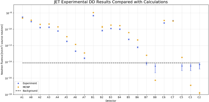
Figure 22. Comparison of experimental and calculated neutron fluence [per source neutron] for each detector for the 2019–2020 D campaign, with detectors ordered by increasing distance for each group A, B, C. The location of each detector is shown in figure 18. Reproduced from [156].
Download figure:
Standard image High-resolution image7.1.2. Shutdown dose experiment
In this experiment, active gamma dosimeters measured the dose rate around JET in a continuous way [161, 162]. Calibrated spherical 1 L air-vented ionization chambers (ICs) are installed in two ex-vessel positions close to the JET horizontal ports in octants 1 and 2. In preparation for DTE2, a third IC suitable for higher dose rates was added in octant 1 for the second part of the 2020 D campaign [162]. Dose rate measurements from the three ICs will be compared to predictions by a number of code packages routinely used in ITER/DEMO design analyses, such as R2Smesh (KIT), MCR2S (CCFE), R2S (UNED) and ORNL-R2S (ORNL), based on the Rigorous Two-Step (R2S) approach, and Advanced D1S (ENEA) and D1SUNED (UNED) based on the direct one-step (D1S) approach (see [163] and references therein).
7.2. Neutron induced activation and damage in fusion materials
7.2.1. Long term irradiation of ITER materials
Samples of fusion relevant structural and functional materials were installed in the vacuum vessel midplane in a specially designed long term irradiation station (LTIS) hosting two multiple sample holders, to investigate the neutron induced activation and damage in these materials. The JET and the LTIS radiation transport models were validated using data from a range of high-purity dosimetry foils irradiated inside the LTIS assemblies during ILW-3 [153]. During the 2019–2020 campaign, 27 samples of real ITER materials provided by F4E (e.g.: EUROFER 97–3 steel, W and CuCrZr materials from the divertor, Inconel 718, CuCrZr and 316 L stainless steel for blanket modules, etc), together with dosimetry foils, were exposed to 2 × 10¹⁴ n cm−2 over a 147 days period. The neutron induced activity measurements identified a number of reaction products in each sample ([164] and figure 23), including those expected from the material composition (58Co, 54Mn, 51Cr, 59Fe, 60Co and 57Co) as well as other products, such as 65Zn, an impurity possibly from Cu or Zn, not listed on the material certificates. For Inconel, the reaction product 182Ta, likely to originate from Ta impurities was also observed.
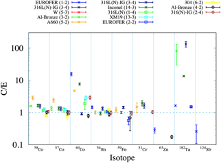
Figure 23. C/E values for a selection of the measured and calculated ITER material isotopes from different material samples (identification reference in parenthesis). The different symbols distinguish different measurement laboratories.
Download figure:
Standard image High-resolution imageA new set of ITER materials is now under radiation in the LTIS for the T/DT campaign (figure 24 left). A second holder (figure 24 right) containing functional materials used in diagnostics and heating systems (incl. several types of alumina, diamond, sapphire, silica, MgAl2O4, BaF2, CaF2, YAG, ZnS) has been installed in the OLTIS. The electrical and optical properties of these materials have been characterised prior to exposure and will be measured again after retrieval from JET. The expected total neutron fluence at the LTIS during the T/DT campaign is up to about 8 × 1015 cm−2 (of which ≈5 × 1015 cm−2 with E > 0.1 MeV) and first wall DT neutron energy spectrum are relevant to ITER diagnostics and heating systems.
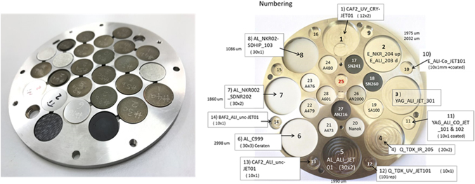
Figure 24. Left: ITER material samples and dosimetry foils in one of the holders of the long term irradiation station of JET. Right: functional samples in the other LTIS holders.
Download figure:
Standard image High-resolution image7.2.2. Tests of fibre optic current sensor for ITER
A similar experiment is devoted to fibre optic current sensor (FOCS), a non-inductive solution for plasma current measurements based on the Faraday effect in optical fibres: in a fibre loop around a current, for linearly polarised light the total polarisation rotation angle θ is directly proportional to the enclosed current I, θ = VI, where V is the Verdet constant which expresses the strength of the Faraday effect in materials and typically varies with wavelength and temperature. Such a system is free of the inherent problems of the electromagnetic sensors whose performance in future burning plasma machines may degrade due the combined effect of steady-state operation and the presence of strong nuclear radiation. FOCS will be installed as a back-up option in ITER where it must comply with stringent requirements (vacuum compatibility, tolerance to strong radiation fields and high temperatures).
Two FOCS systems are installed on JET [165] to assess their performance in presence of multi-MA range currents and high neutron flux, from ∼1010 cm−2 s−1 in D operations to ∼1012 cm−2 s−1 in DT on the external surface of the vacuum vessel, comparable with that expected in ITER [166]. During 2020 JET operation, measurements were carried out, comparing two FOCS systems. The first operates in transmission mode and includes a 100 m long fibre link between the sensing fibre and the data acquisition hardware. The second operates in reflection mode, with a Faraday mirror. It was shown that the FOCS systems can operate for a long period at the same error level without additional corrections. In transmission mode, at the maximal current, the measurement error (i.e. the difference between FOCS and reference measurements from the continuous external Rogowski coil) is within 1%. Working in reflection mode doubles the sensor sensitivity because the effective sensing fibre length is doubled. With a fixed resolution of the polarisation state detection, this corresponds to a reduction of the measurement error. The tests confirmed that the reciprocal birefringence effects are completely suppressed when no current circulates in the FOCS loop in reflection mode.
Expected effects of the ITER radiation environment on FOCS are transmission degradation and changes to the Verdet constant. The former was intensively addressed via fission reactor experiments, though the applicability of those studies can be questioned due to the absence of 14 MeV neutrons, this will be addressed by the DT campaign which will provide a representative 14 MeV flux. Data accumulated during non-DT operation are also useful. The Verdet constant was monitored during JET operation in 2016–2019, see figure 25. The variations of the Verdet constant are due to a combination of FOCS and the reference Rogowski measurement errors. No systematic long-term trend is observed, indicating that radiation-induced changes are not significant within the radiation flux level produced so far.

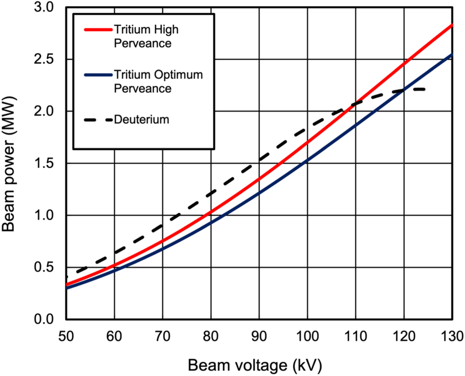
Figure 25. The normalised Verdet constant for FOCS 1 (F1, red) and FOCS 2 (F2, blue) systems during JET operation for shots from 89 870 to 96 563. The estimated values are 0.696 ± 0.010 and 0.672 ± 0.013 rad MA, respectively.
Download figure:
Standard image High-resolution image
8. Conclusive remarks
The technical and scientific preparation for T and DT operations took place over several years and was completed in 2019–2020. The scenario development to higher IP and power successfully overcame the JET-ILW challenges (W control and tolerable divertor power load compatible with high confinement) to deliver the sustained high fusion power plasmas needed for DTE2. This also expanded JET-ILW parameter space, leading to new physics of interest to ITER, e.g. pedestal impurity screening, small ELMs scenarios in seeded and unseeded plasmas, demonstration that Ne compares favourably to N2 as seed gas. A wide range of experiments on the impact of isotope and mixed species plasmas was performed, confirming or challenging assumptions and reduced models used for predicting ITER, and ready to be tested in tritium and in D–T. An extensive set of JET SPI experiments provided ITER with important information for preparing its DMS, including a possible new way to control RE. JET unique environment provided key results from PCF and nuclear technology experiments, testing materials and components for ITER, and providing the data needed to validate assumptions and codes for the design and safe operation of ITER and DEMO.
Acknowledgments
This work has been carried out within the framework of the EUROfusion Consortium and has received funding from the Euratom research and training programme 2014–2018 and 2019–2020 under Grant Agreement No. 633053. The views and opinions expressed herein do not necessarily reflect those of the European Commission.