Article

Effect of Topology Parameters on Physical–Mechanical Properties of Magnetic PLA 3D-Printed Structures

1
Department of Technical Studies, College of Polytechnics Jihlava, Tolstého 16, 586 01 Jihlava, Czech Republic
2
Institute of Theoretical and Applied Mechanics of the Czech Academy of Sciences, Centre Telč, Prosecká 809/76, 190 00 Prague, Czech Republic
3
Department of Machining, Assembly and Engineering Technology, Faculty of Mechanical Engineering, VSB-TU Ostrava, 17. Listopadu 2172/15, 708 00 Ostrava-Poruba, Czech Republic
4
Department of Civil Engineering, Faculty of Technology, Institute of Technology and Business, Okružní 517/10, 370 01 České Budějovice, Czech Republic
*
Author to whom correspondence should be addressed.
Magnetochemistry 2023, 9(12), 232; https://doi.org/10.3390/magnetochemistry9120232
Submission received: 25 October 2023 / Revised: 1 December 2023 / Accepted: 13 December 2023 / Published: 18 December 2023
(This article belongs to the Section Magnetic Materials)

Abstract

:
This work aims to characterize 3D-printed structures composed of a thermoplastic material (polylactic acid (PLA)) containing a combination of magnetic particles composed of iron(III) oxide (hematite) and iron(II)–iron (III) oxide (magnetite) with various infill densities and print orientations in regard to their possible processing by Fused Filament Fabrication additive technology. The correct processing temperatures have been determined using thermal analysis, and the paramagnetic and mechanical properties of the samples have been tested. The relative permeability has been identified to be strongly dependent on the topology parameters of the tested samples. The results of the inductance values for the samples without magnetic additives (infill densities 50% and 100%) have been detected to be comparable; nonetheless, the magnetic samples with 100% infill density has been found to be about 50% higher. A similar trend has been observed in the case of the values of the relative permeability, where the magnetic samples with 100% infill density have been measured as having an about 40% increased relative permeability in the comparison with the samples without magnetic additives (infill densities 20–100%). Finite Element Modelling (FEM) simulations have been applied to determine the magnetic field distributions and, moreover, to calculate the holding forces of all the printed samples. The maximum value of the holding force for the minimum distance of the plastic plate has been found to reach a value of almost 300 N (magnetic sample with 100% infill density). The obtained comprehensive characterization of the printed samples may be utilized for designing and tuning the desired properties of the samples needed in various industrial applications.

1. Introduction

Additive manufacturing is applied in various industrial sectors, such as medicine [1,2,3], engineering [4,5,6,7], and food industries [8]. It represents a prominent way of processing various types of materials [9]. Fused Filament Fabrication (FFF), developed by S. Scott Crump in 1989 [10], which processes materials in the form of filaments composed of thermoplastics or elastomers, is one of the most widely used additive technologies. FFF additive technology offers many benefits, such as affordability, suitability for commercial and hobby applications, the accessibility of the processing materials, and usability for products with demanding shapes. The different types of thermoplastic materials, e.g., polylactic acid (PLA) [11,12,13], polyethylene terephthalate-glycol (PET-G) [14,15,16], acrylonitrile-butadiene-styrene (ABS) [17,18,19], ABS/thermoplastic polyurethane (TPU) [20], polycarbonate (PC) [21,22], polypropylene (PP) [23,24,25], polyvinylchloride (PVC) [26], polyethylene terephthalate (PET) [27,28], were found to be suitable for processing by this technique.
One of the most used thermoplastic materials processed by FFF technology is PLA because it is an ecologically degradable thermoplastic, and it does not produce odors or toxic fumes when printed, making it easy to 3D print with low product deformation. PLA has a low melting temperature and minimal warpage and, compared with ABS and nylon, represents a material of higher strength and rigidity. [29]. However, its non-magneticity limits PLA’s usage for specific applications like components designed for simple low-current circuits and capacitive touch sensors [30,31,32]. For this reason, various magnetic additives are used to modify the properties of PLA [33,34]. Additives containing iron (Fe) are commonly employed [35,36,37,38,39,40]. In addition, incorporating Fe particles within polymeric structures influences the conductance and shielding capacity of printed products [41,42,43]. In general, Fe particles are present as iron oxides—e.g., hematite (Fe₂O₃) and magnetite (Fe₃O₄) [44]. In contrast to magnetite, hematite becomes magnetic after heating or exposure to a strong magnetic field [45]. Moreover, hematite can become weakly magnetic after mixing with small amounts of magnetite [46]. Magnetite is a ferrimagnetic phase with high magnetization (∼92 A·m2·kg−1) and low coercivity (7958–31,831 A·m−1), while hematite represents an antiferromagnetic phase with a small magnetization (∼0.4 A·m2·kg−1) and high coercivity (∼79,577–318,310 A·m−1) [47,48,49].
The particle size distribution and shape of the magnetic particles influence their properties, and therefore, these material properties have a remarkable impact on the final parameters of printed products. For example, the magnetic behavior of nanoparticles in an external magnetic field was identified to be strongly influenced by their size [50]. In FFF technology, an important parameter is not only the size of the used particles, but their surface quality as well [51].
This work is focused on optimizing the infill density of printed structures composed of PLA containing hematite and magnetite to gain control of the permeability of printed samples, quality of processing, and economic sustainability. Finite Element Modelling (FEM) was used to calculate the magnetic field distributions and holding forces of the polymeric composites.

2. Materials and Methods

2.1. Materials

Filaments composed of PLA containing hematite and magnetite (Proto-pasta Magnetic Iron PLA 1.75 mm, Vancouver, WA, USA), with density of 1.24 g·cm−3 were used to prepare 3D test samples [52]. The reference sample was printed from transparent filaments composed of PLA without magnetic powders (Ø 1.75 ± 0.05 mm; density of 1.25 g·cm−3; BASF Ultrafuse PLA-0001A075 PLA Natural, Innofil3D BV, Emmen, The Netherlands) [53].

2.2. Preparation of Samples

3D printing was performed on Original Prusa I3 MK3S (Prusa Research a.s., Prague, Czech Republic, nozzle size 0.4 mm), implementing the FFF technique. PrusaSlicer 2.6.0 software (Prusa Research a.s., Prague, Czech Republic) set up the printing parameters and exported them to a post-processing format (*g-code format). The samples were printed as circles (see Figure S1) with a diameter of 60/50 mm (outer/inner) and a height of 20 mm to determine the magnetic properties of paramagnetic materials using the toroid measurement method [54,55,56,57,58]. A gyroid structure with an infill density of 20%, 50%, and 100% (Figure S1) was selected. Samples were marked according to the infill density, namely, 20X_y, 50X_y, and 100X_y, where X = R for samples composed of pure PLA and X = A for samples composed of PLA and magnetic powders, y = print orientation z or xy. The printing temperature was 215 °C, whereas the plate temperature was 60 °C. The 3D print speed was set to 70 mm·s−1. The layer thickness and extrusion width were 0.15 mm and 0.4 mm, respectively. A 3D nozzle with a hole diameter of 0.4 mm was used. Table 1 summarizes all the relevant parameters of the produced samples. At least five replicates were produced for each sample type. Samples for magnetic and compressive testing were only prepared in xy print orientation because z-orientation printing would require support for the sample model.
Samples for tensile and bending tests samples were prepared using the same 3D printing parameters mentioned above (see in Figure S2). Dimension of samples used for bending and compressive tests were (4 × 10 × 80) mm (t × w × l) and (30 × 30 × 30) mm (t × w × l), respectively. The design and dimensions of samples used for tensile tests dimensions are shown in Figure 1. Samples for mechanical properties testing (tensile and bending test) were printed in two print orientations, xy and z, and for compressive test, only in print orientation xy.

2.3. Methods

The quality of the used filaments was verified using Fourier transform infrared (FT-IR) spectroscopy with a Nicolet iN10 instrument (Thermo Fisher Scientific, Waltham, MA, USA). FT-IR spectra were obtained using the attenuated total reflectance (ATR) method with a diamond crystal, and spectra were obtained from 3500 cm−1 to 600 cm−1.
The magnetic powders, filaments, and cross-sections of the printed samples were characterized using a Keyence VHX-6000 optical microscope (Keyence, Itasca, IL, USA).
Thermal behavior (mass change and heat flow) of the filament samples was followed by performing simultaneous thermogravimetry (TGA) and differential thermal analysis (DTA) under non-isothermal conditions, using a TGA 2 instrument (Mettler-Toledo, Columbus, OH, USA). The measurements were performed in a nitrogen atmosphere at a heating rate of 20 °C·min−1, in the range of 30 to 1000 °C.
The magnetic powder content was determined based on the standard ČSN EN ISO 3451-1 [59]. Three replicates were used for determination. The procedure consisted of determining the combustible magnetic powders content (w, wt.%), using the calculation by (1):
w = ( 1 m 1 m 2 ) × 100 ,
where m1 is weight after combustion (g), m2 is the weight before combustion (g).
The structure of magnetic powder was investigated with a scanning electron microscope (SEM) Quanta 450 FEG (FEI, Brno, CZE) using a secondary electron detector. Observations were conducted on fractured surfaces at 20 kV accelerating voltage. Samples were placed on carbon tape and coated with a 7 nm thick layer of gold.
X-ray powder diffraction (XRPD) data for magnetic powder were collected at 40 kV and 40 mA with a Bragg–Brentano θ-θ diffractometer (Bruker D8 Advance) (Bruker, Billerica, MA, USA), Cu Kα radiation (λ = 1.5418 Å). Data were collected in the angular range 20–70° 2θ counting 0.4 s for each step of 0.0102° 2θ. Quantitative phase analysis used Rietveld refinements in software TOPAS 4.2 (Bruker AXS, Bruker, Billerica, MA, USA).
The magnetic properties of the printed structures were measured on toroidal samples equipped with an excitation winding. Since the resulting printed material exhibits paramagnetic properties with a small value of relative permeability and almost no coercivity, measurements of the inductance of the toroidal core using L bridges were used to determine the permeability value. An LRC meter (MCP Precision LCR Metr BR217) was used. The inductance measurement was performed at a frequency of 1 kHz.
An Ansys-Maxwell software (Ansys Inc., Canonsburg, PA, USA) using FEM (Figures S3 and S4) calculation methods [60,61,62] was used to evaluate the magnetic field and holding force of the typical configurations of the permanent magnet and the printed magnetic plastic disc. The magnetic field simulations and the holding force calculations were carried out for the configuration depicted in Figures S3 and S4. The experiment was performed axisymmetrically along the z-axis. The simulation used a permanent disk magnet (composed of FeNdB (marked as N35SH)) with an outer diameter, inner diameter, and thickness of 66, 30, and 4 mm, respectively. The coercive force of this magnet was 900 kA·m−1, and the remanent induction was 1.2 T. The upper part of the magnet was surrounded by a ferromagnetic clutch made of grade 1008 steel, represented by the BH characteristic. This system formed the source of the magnetic field and holding force acting on the magnetic plastic plate prepared by 3D printing. The dimensions of the magnetic plastic plate were a 200 mm outer diameter and 5 mm thickness. To determine the holding force, the distance of the plastic plate from the magnet was changed in the range of 0 to 20 mm with a step of 1 mm.
A universal mechanical device (Instron 3345, Instron, Norwood, MA, USA) with a maximum capacity load of 5 kN was used to test the tensile, compressive, and bending properties of the printed samples with a different print orientation. All three tests were undertaken at a 1 mm·min−1 speed with a load of 5 kN. The tensile test was performed according to ČSN EN ISO 527-2 [63], and the bending test was performed according to ČSN EN ISO 178 [64], and the compressive test was carried out according to ČSN EN ISO 604 [65].

3. Results

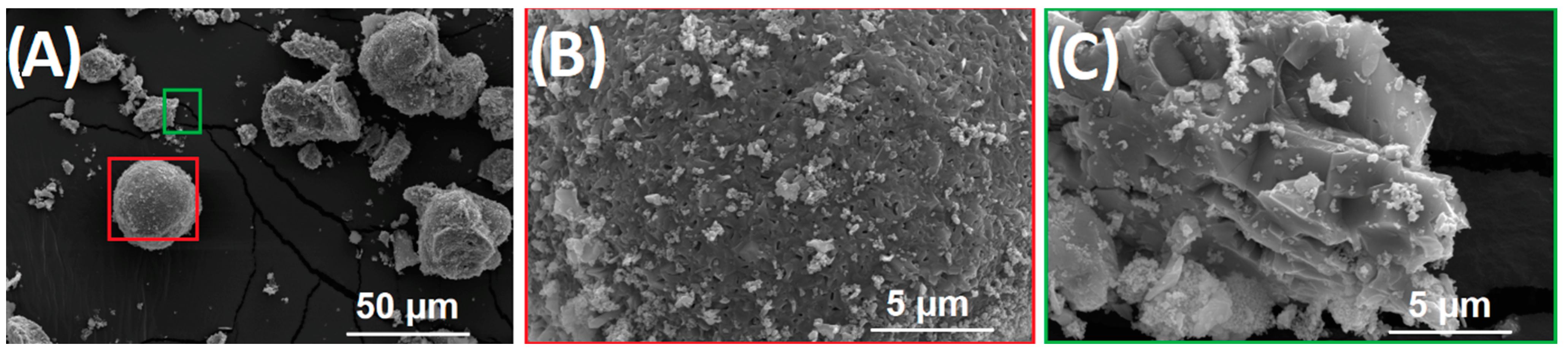
3.1. Characterization of Material

As depicted in Figure 2, the chemical composition of the PLA material was confirmed by FT-IR spectroscopy, where a good match of the measured spectrum with the results in the literature [66] was obtained. The spectrum shows a band at 1750 cm−1, which can be attributed to the CO vibrations of the ester groups, peaks around 3000 cm−1 for –CH stretching, and peaks around 1000 cm−1 for C-O stretching. Peaks in the 400–615 cm−1 range are characteristic of Fe-O present in hematite and magnetite [67]. In magnetic PLA, signals of iron oxides are in strong overlap with PLA. Clear evidence of their presence was obtained from the DTA-TG analysis, microscopic observations, and XRPD analysis.
The total content of the magnetic particles in magnetic PLA determined using the combustion process was found to be 48.15 ± 0.5 wt.%. Based on the XRPD analysis, the magnetic powder was found to be composed of 72.5 (4) wt.% of hematite (Iron(III) oxide) and 27.5 (4) wt.% of magnetite (Iron(II)–Iron(III) oxide) (XRPD patterns are depicted in Figures S5 and S6). The morphologies of the magnetic particles are shown at a lower magnification in Figure S7 and, in more detail, in Figure 3. It is visible that magnetic powders contain various shapes with large variations in size, from a few microns up to big clusters with diameters of hundreds of microns. In line with the XRPD results, the SEM observations revealed two types of particles. The first type of particle is highlighted using an inserted red square in Figure 3A (its surface is depicted at a higher magnification in Figure 3B), and the second type of particle is partially highlighted using a green square in Figure 3A, and its morphology at a higher magnification in Figure 3C).
The TGA curves recorded for the PLA and magnetic PLA are shown in Figure 4. The glass transition temperature (Tg) was determined to be 62.92 °C and 64.30 °C for the nonmagnetic and magnetic filaments, respectively. The results are in agreement with the values from the literature, around 60 °C [68]. For the setting of the bed temperatures, 60 °C is recommended [69]. The melting point (Tm) was determined to be 146.83 °C for the reference sample and 148.98 °C for the filament containing mixed oxides. The homogeneous distribution of the magnetic powders in the PLA was confirmed using microscopic filament observations (Figure 5).

3.2. Magnetic Properties Results

The determined inductance and relative permeability values of the printed samples are summarized in Table 2. To determine the BH characteristics, it would be necessary to supplement the measured samples with additional sensing windings and use some hysteresis graphs, as described in the references [60,70,71]. No big changes were found in the samples composed of only PLA (20R–100R) in both measured magnetic properties. Nonetheless, a gradual increase in the inductance and relative permeability according to the infill density was visible for the printed samples of PLA and magnetic particles. As visualized in Figure S8, the dependence of the relative permeability as a function of the increasing infill density for the samples containing additives was found to be linear. The inductance values were predicted to be about 22% higher if the 20A and 100A samples were compared. The same trend was found for the relative permeability compared to the 20A sample. The values were higher for ca. 36 and 43% for samples 50A and 100A, respectively. Such a beneficial effect on the magnetic properties is in good agreement with previously reported results [71]. Moreover, it was confirmed that a mixture of hematite and magnetite is more effective in increasing the relative permeability than a previously used mixture of hematite and rutile (Ti(II) dioxide; the relative permeability for 100% infill was determined to be only 1.39) [71].

3.3. Mechanical Properties Results

From the point of view of the application potential, the mechanical properties of the printed products are one of the key properties [72,73]. The distribution of the magnetic powders in the tested samples influences the magnetic and mechanical property results. The homogeneous distribution of the 3D-printed samples with 100% infill density at two print orientations was confirmed using microscopic observations (Figure 6). Examples of sample cross-sections in two print orientations for the pure PLA are shown in Figure 6A,B. Figure 6C,D show the samples with magnetic particles. Small differences are already visible due to the different print orientations, but the distribution of the magnetic powders appears to be homogeneous.
The tensile, bending, and compressive test results are summarized in Table 3, Table 4 and Table 5. A gyroid structure was used to prepare samples with infill densities of 20% and 50%. This is one of the few 3D structures that provide high support in all directions. It is also relatively fast to print. It saves material and does not overlap in a layer. The results of the tensile test show that as the infill density of the samples decreases, the modulus of elasticity, tensile strength, and tensile strain decrease. These trends were detected to be the same for both types of polymeric samples. When comparing the materials, it can be seen that the samples with magnetic particles show higher values of elastic modulus.
On the contrary, the tensile strength was lower and comparable to the tensile strain. The print orientation has a significant effect on the mechanical properties. The samples printed in the z orientation showed higher values of the modulus of elasticity and tensile strength. The tensile strain was comparable. The same trend for the print and infill density orientation stage was also demonstrated in a study [74].
Bending tests (Table 4) showed no significant differences for the PLA samples printed in different orientations. On the other hand, the samples containing magnetic particles were detected to have the highest values of the modulus of elasticity and bending stress in the case of the samples printed in the z orientation. In general, the magnetic particle samples showed better bending mechanical properties than the pure PLA.
The modulus of elasticity and compressive strength results are summarized in Table 5. From Table 5, the negative effect of the magnetic powders added to the polymer filament is evident when the results for the modulus and compressive strength are lower than for the reference samples. The modulus of elasticity is about 5% higher for the reference samples, i.e., without the content of magnetic particles, compared to the samples with the content of magnetic particles. A similar trend can also be seen in the compressive strength values, where the samples without magnetic particles showed approximately 25% higher values than the samples with additives. These trends correlate with the previously reported values [75] of products intended for bioapplications.

3.4. Magnetic Field Simulation and Calculation of Force Effects

The examples of FEM simulations, based on the excitation using permanent magnets [60,61,62], of the magnetic field intensity (H) and magnetic induction (B) for sample 100A using a disc magnet are depicted in Figure 7. The result of the simulations is the distribution of the magnetic field in the magnet, the plastic plate with the magnetic powders, and the surrounding air. The distributions of H and B for the model with zero air gap are shown in Figure 7a,b. For the experimental set-up with the plastic plate distance of 10 mm, the distributions are shown in Figure 7c,d. After the post-process calculations, the magnitudes of the applied forces were obtained, and the data were graphically visualized in Figure 8. The force effects upon the exposure of the materials to an external magnetic field is one of the critical parameters determining the applicability of printed products [76].
As is shown in Figure 8, the force effects were found to be intensely dependent on the used infill densities of the printed samples: the force was gradually increased with the increasing infill densities. In addition, in Figure 6, the holding forces were modeled also for the magnet with an Fe yoke. In comparison with the disc magnet, the set-up with the Fe yoke magnet showed up to ca. four times higher values of forces from zero gaps up to a distance of around 7.5 mm. Such high holding force values can already be widely applied in technical practice as actuators or electromotors [76,77]. Above the 12.5 mm distance, no significant differences were visible. In comparison with the results in the literature [71], it is evident that holding forces testing using the same principle of this experiment but different types of magnet was around one order of magnitude higher in the system with PLA–iron oxide additives. Increasing the infill density and magnetic particle content shows a similar trend.
Thus, the composites produced in this work may ensure a better magnetic holding force capability for selected objects. The printed samples may find utilization in cases where it is necessary to have suitable force interactions and/or conduct magnetic flux, such as sensors and switches.

4. Conclusions

This work investigated the physical and mechanical properties and FEM simulations of printed samples of pure PLA and PLA-containing iron oxides (hematite and magnetite) with different infill densities (20–100%) produced using Fused Filament Fabrication technology.
The influence of the 3D printing orientation and infill density on the mechanical properties in terms of the tension, compression, and bending was demonstrated. The effect of the 3D printing orientation is negligible, in the range of standard deviations for all three types of stress. The results of the tensile tests show that as the infill density increases, the values of the modulus and the tensile strength increase while the tensile elongation decreases. There was observed an increase in the modulus of elasticity values but, at the same time, a decrease in the tensile strength and tensile strain with the application of magnetic particles was recorded as well. Similar trends were observed in view of the bending test results. As the infill density increased, the modulus of elasticity and bending strength increased. The samples with the addition of magnetic particles showed a decrease in the values of the bending strength and elongation and, on the contrary, an increase in the modulus of elasticity values. The compression tests confirmed a trend where the samples with a higher infill density showed higher values of the modulus of elasticity and compressive strength. The mechanical properties obtained, together with the knowledge of how the final samples are stressed, provide a good indicator for designing products using FFF technology. The results of the magnetic property measurements showed that the inductance and relative permeability values of the 50R_xy and 100R_xy samples were comparable. However, the inductance and relative permeability of the 100A_xy sample were found to be about 50% and 40% higher, respectively. From FEM, the holding forces were calculated, and their values were gradually detected to increase with higher infill densities for both experimental set-ups. The Fe yoke-type magnet application resulted in ca. four times higher forces at zero gap. The maximum value of the holding force for the minimum distance of the plastic plate reached a value of almost 300 N (sample 100A). Printed samples with such characteristics can hold medium-weight objects. As was shown, FFF technology can successfully produce a novel class of samples with unique properties. In general, FFF represents a fast and relatively cheap method to fabricate samples with irregular shapes and is intended for specific applications in different industries and in medicine-oriented branches as well. In addition, the selection of the sufficient infill density of printed structures is an important key to maintaining their required properties, and, at the same time, it can help significantly save the amount of input raw materials used and optimize the time needed for printing. Thus, engineer-tuned magnetic PLA 3D printing structures represent advanced materials that may lead to important production efficiency and help mitigate 3D printing-related environmental impacts positively.

Supplementary Materials

The following supporting information can be downloaded at https://www.mdpi.com/article/10.3390/magnetochemistry9120232/s1, Figure S1. The example of sample layout when printing with xy orientation, where there are always two types of samples in each image; on the left a sample of 20% infill density, on the right a sample of 50% infill density; Figure S2. Examples of printed samples for individual types of testing; Figure S3. Examples of printed samples for individual types of testing; Figure S4. Implementation of the computational network of the magnet model and the holding plastic plate; Figure S5. XRD pattern for magnetic additive with indication of corresponding phases, where M is for magnetite, H is for hematite; Figure S6. Graphical output of the Rietveld refinement of the magnetic product: blue line—experimental spectrum; red line—calculated pattern; grey line—difference plot. RWP value characterizing the quality of fit was 2.665; Figure S7. Microscopic image of used magnetic powder in filament; Figure S8. Dependence of relative permeability on increasing infill density in samples with magnetic additive content.

Author Contributions

Conceptualization. L.Z., M.M.; methodology. M.M., L.Z., and M.P.; software. M.M. and M.P.; validation. R.Š. and J.P.; formal Analysis. L.Z., M.M., and J.P.; investigation. M.M. and L.Z.; writing—original draft preparation. L.Z., R.Š., and M.M.; writing—review and editing. J.P. and R.Š.; visualization. M.P.; project administration. J.P. All authors have read and agreed to the published version of the manuscript.

Funding

This research was funded by the Czech Science Foundation GA ČR (Grant Number GC23-04676J) and the College of Polytechnics Jihlava, under Grant no. INT/2023/0008 ”Study of the fiber-matrix interfacial interface of samples prepared by 3D printing with regard to physical–mechanical properties“ by the Czech Academy of Sciences, Institute of Theoretical and Applied Mechanics-RVO 68378297, and further by the Institute of Technology and Business, under project No. 03SVV2325. This research was also funded by the European Union under the REFRESH—Research Excellence for Region Sustainability and High-tech Industries—project number CZ.10.03.01/00/22_003/0000048 via the Operational Programme Just Transition.

Institutional Review Board Statement

Not applicable.

Informed Consent Statement

Not applicable.

Data Availability Statement

No new data were created or analyzed in this study. Data sharing is not applicable to this article.

Conflicts of Interest

The authors declare no conflict of interest.

References

  1. Culmone, C.; Smit, G.; Breedveld, P. Additive manufacturing of medical instruments: A state-of-the-art review. Addit. Manuf. 2019, 27, 461–473. [Google Scholar] [CrossRef]
  2. Kessler, A.; Hickel, R.; Reymus, M. 3D printing in dentistry—State of the art. Oper. Dent. 2020, 45, 30–40. [Google Scholar] [CrossRef] [PubMed]
  3. Serra, T.; Mateos-Timoneda, M.A.; Planell, J.A.; Navarro, M. 3D printed PLA-based scaffolds: A versatile tool in regenerative medicine. Organogenesis 2013, 9, 239–244. [Google Scholar] [CrossRef] [PubMed]
  4. Böckin, D.; Tillman, A.-M. Environmental assessment of additive manufacturing in the automotive industry. J. Clean. Prod. 2019, 226, 977–987. [Google Scholar] [CrossRef]
  5. Alexander, C. Streamlining automotive production with additive manufacturing. Quality 2018, 57, 37–39. [Google Scholar]
  6. Zhakeyev, A.; Wang, P.; Zhang, L.; Shu, W.; Wang, H.; Xuan, J. Additive manufacturing: Unlocking the evolution of energy materials. Adv. Sci. 2017, 4, 1700187. [Google Scholar] [CrossRef] [PubMed]
  7. Hambach, M.; Rutzen, M.; Volkmer, D. Properties of 3D-printed fiber-reinforced Portland cement paste. In 3D Concrete Printing Technology; Elsevier: Amsterdam, The Netherlands, 2019; pp. 73–113. [Google Scholar]
  8. Lille, M.; Nurmela, A.; Nordlund, E.; Metsä-Kortelainen, S.; Sozer, N. Applicability of protein and fiber-rich food materials in extrusion-based 3D printing. J. Food Eng. 2018, 220, 20–27. [Google Scholar] [CrossRef]
  9. Gibson, I.; Rosen, D.; Stucker, B.; Khorasani, M. Materials for additive manufacturing. In Additive Manufacturing Technologies; Springer: Berlin/Heidelberg, Germany, 2021; pp. 379–428. [Google Scholar]
  10. Williams, L.D.; Williams, L. Additive manufacturing or 3d scanning and printing. In Manufacturing Engineering Handbook; McGraw-Hill: New York, NY, USA, 2015. [Google Scholar]
  11. Alam, F.; Shukla, V.R.; Varadarajan, K.M.; Kumar, S. Microarchitected 3D printed polylactic acid (PLA) nanocomposite scaffolds for biomedical applications. J. Mech. Behav. Biomed. Mater. 2020, 103, 103576. [Google Scholar] [CrossRef]
  12. Laureto, J.; Tomasi, J.; King, J.A.; Pearce, J.M. Thermal properties of 3-D printed polylactic acid-metal composites. Prog. Addit. Manuf. 2017, 2, 57–71. [Google Scholar] [CrossRef]
  13. Tao, Y.; Liu, M.; Han, W.; Li, P. Waste office paper filled polylactic acid composite filaments for 3D printing. Compos. Part B Eng. 2021, 221, 108998. [Google Scholar] [CrossRef]
  14. Ferreira, I.; Vale, D.; Machado, M.; Lino, J. Additive manufacturing of polyethylene terephthalate glycol/carbon fiber composites: An experimental study from filament to printed parts. Proc. Inst. Mech. Eng. Part L J. Mater. Des. Appl. 2019, 233, 1866–1878. [Google Scholar] [CrossRef]
  15. Dolzyk, G.; Jung, S. Tensile and fatigue analysis of 3D-printed polyethylene terephthalate glycol. J. Fail. Anal. Prev. 2019, 19, 511–518. [Google Scholar] [CrossRef]
  16. Mansour, M.; Tsongas, K.; Tzetzis, D.; Antoniadis, A. Mechanical and dynamic behavior of fused filament fabrication 3D printed polyethylene terephthalate glycol reinforced with carbon fibers. Polym. Plast. Technol. Eng. 2018, 57, 1715–1725. [Google Scholar] [CrossRef]
  17. Vidakis, N.; Petousis, M.; Maniadi, A.; Koudoumas, E.; Liebscher, M.; Tzounis, L. Mechanical properties of 3D-printed acrylonitrile–butadiene–styrene TiO2 and ATO nanocomposites. Polymers 2020, 12, 1589. [Google Scholar] [CrossRef] [PubMed]
  18. Farcas, M.T.; Stefaniak, A.B.; Knepp, A.K.; Bowers, L.; Mandler, W.K.; Kashon, M.; Jackson, S.R.; Stueckle, T.A.; Sisler, J.D.; Friend, S.A. Acrylonitrile butadiene styrene (ABS) and polycarbonate (PC) filaments three-dimensional (3-D) printer emissions-induced cell toxicity. Toxicol. Lett. 2019, 317, 1–12. [Google Scholar] [CrossRef] [PubMed]
  19. Vidakis, N.; Petousis, M.; Maniadi, A.; Koudoumas, E.; Vairis, A.; Kechagias, J. Sustainable additive manufacturing: Mechanical response of acrylonitrile-butadiene-styrene over multiple recycling processes. Sustainability 2020, 12, 3568. [Google Scholar] [CrossRef]
  20. De León, A.S.; Domínguez-Calvo, A.; Molina, S.I. Materials with enhanced adhesive properties based on acrylonitrile-butadiene-styrene (ABS)/thermoplastic polyurethane (TPU) blends for fused filament fabrication (FFF). Mater. Des. 2019, 182, 108044. [Google Scholar] [CrossRef]
  21. Reich, M.J.; Woern, A.L.; Tanikella, N.G.; Pearce, J.M. Mechanical properties and applications of recycled polycarbonate particle material extrusion-based additive manufacturing. Materials 2019, 12, 1642. [Google Scholar] [CrossRef]
  22. Fang, L.; Yan, Y.; Agarwal, O.; Seppala, J.E.; Hemker, K.J.; Kang, S.H. Processing-structure-property relationships of bisphenol-A-polycarbonate samples prepared by fused filament fabrication. Addit. Manuf. 2020, 35, 101285. [Google Scholar] [CrossRef]
  23. Jiang, C.; Wang, A.; Bao, X.; Ni, T.; Ling, J. A review on geopolymer in potential coating application: Materials, preparation and basic properties. J. Build. Eng. 2020, 32, 101734. [Google Scholar] [CrossRef]
  24. Vidakis, N.; Petousis, M.; Tzounis, L.; Maniadi, A.; Velidakis, E.; Mountakis, N.; Papageorgiou, D.; Liebscher, M.; Mechtcherine, V. Sustainable additive manufacturing: Mechanical response of polypropylene over multiple recycling processes. Sustainability 2021, 13, 159. [Google Scholar] [CrossRef]
  25. Bachhar, N.; Gudadhe, A.; Kumar, A.; Andrade, P.; Kumaraswamy, G. 3D printing of semicrystalline polypropylene: Towards eliminating warpage of printed objects. Bull. Mater. Sci. 2020, 43, 171. [Google Scholar] [CrossRef]
  26. Calafel, I.; Aguirresarobe, R.H.; Peñas, M.I.; Santamaria, A.; Tierno, M.; Conde, J.I.; Pascual, B. Searching for rheological conditions for FFF 3D printing with PVC based flexible compounds. Materials 2020, 13, 178. [Google Scholar] [CrossRef] [PubMed]
  27. Zander, N.E.; Gillan, M.; Lambeth, R.H. Recycled polyethylene terephthalate as a new FFF feedstock material. Addit. Manuf. 2018, 21, 174–182. [Google Scholar] [CrossRef]
  28. Carrete, I.A.; Quiñonez, P.A.; Bermudez, D.; Roberson, D.A. Incorporating textile-derived cellulose fibers for the strengthening of recycled polyethylene terephthalate for 3D printing feedstock materials. J. Polym. Environ. 2021, 29, 662–671. [Google Scholar] [CrossRef]
  29. Pei, E.; Shen, J.; Watling, J. Direct 3D printing of polymers onto textiles: Experimental studies and applications. Rapid Prototyp. J. 2015, 21, 556–571. [Google Scholar] [CrossRef]
  30. Bollig, L.M.; Hilpisch, P.J.; Mowry, G.S.; Nelson-Cheeseman, B.B. 3D printed magnetic polymer composite transformers. J. Magn. Magn. Mater. 2017, 442, 97–101. [Google Scholar] [CrossRef]
  31. Patton, M.V.; Ryan, P.; Calascione, T.; Fischer, N.; Morgenstern, A.; Stenger, N.; Nelson-Cheeseman, B.B. Manipulating magnetic anisotropy in fused filament fabricated parts via macroscopic shape, mesoscopic infill orientation, and infill percentage. Addit. Manuf. 2019, 27, 482–488. [Google Scholar] [CrossRef]
  32. Huber, C.; Abert, C.; Bruckner, F.; Groenefeld, M.; Muthsam, O.; Schuschnigg, S.; Sirak, K.; Thanhoffer, R.; Teliban, I.; Vogler, C. 3D print of polymer bonded rare-earth magnets, and 3D magnetic field scanning with an end-user 3D printer. Appl. Phys. Lett. 2016, 109, 162401. [Google Scholar] [CrossRef]
  33. Gray, R.L. Hindered amine light stabilizers: Recent developments. Plast. Addit. 1998, 1, 360–371. [Google Scholar]
  34. Pritchard, G. Plastics Additives: An AZ Reference; Springer Science & Business Media: Berlin/Heidelberg, Germany, 2012; Volume 1, ISBN 9401158622. [Google Scholar]
  35. Gangopadhyay, S.; Hadjipanayis, G.C.; Dale, B.; Sorensen, C.M.; Klabunde, K.J.; Papaefthymiou, V.; Kostikas, A. Magnetic properties of ultrafine iron particles. Phys. Rev. B 1992, 45, 9778. [Google Scholar] [CrossRef] [PubMed]
  36. Bødker, F.; Hansen, M.F.; Koch, C.B.; Lefmann, K.; Mørup, S. Magnetic properties of hematite nanoparticles. Phys. Rev. B 2000, 61, 6826. [Google Scholar] [CrossRef]
  37. Varanda, L.C.; Jafelicci, M., Jr.; Goya, G.F. Magnetic properties of spindle-type iron fine particles obtained from hematite. J. Magn. Magn. Mater. 2001, 226, 1933–1935. [Google Scholar] [CrossRef]
  38. Tadić, M.; Čitaković, N.; Panjan, M.; Stojanović, Z.; Marković, D.; Spasojević, V. Synthesis, morphology, microstructure and magnetic properties of hematite submicron particles. J. Alloys Compd. 2011, 509, 7639–7644. [Google Scholar] [CrossRef]
  39. King, J.G.; Williams, W.; Wilkinson, C.D.W.; McVitie, S.; Chapman, J.N. Magnetic properties of magnetite arrays produced by the method of electron beam lithography. Geophys. Res. Lett. 1996, 23, 2847–2850. [Google Scholar] [CrossRef]
  40. Sodipo, B.K.; Noqta, O.A.; Aziz, A.A.; Katsikini, M.; Pinakidou, F.; Paloura, E.C. Influence of capping agents on fraction of Fe atoms occupying octahedral site and magnetic property of magnetite (Fe3O4) nanoparticles by one-pot co-precipitation method. J. Alloys Compd. 2023, 938, 168558. [Google Scholar] [CrossRef]
  41. Makridis, A.; Okkalidis, N.; Trygoniaris, D.; Kazeli, K.; Angelakeris, M. Composite magnetic 3D-printing filament fabrication protocol opens new perspectives in magnetic hyperthermia. J. Phys. D Appl. Phys. 2023, 56, 285002. [Google Scholar] [CrossRef]
  42. Cazin, I.; Rossegger, E.; Roppolo, I.; Sangermano, M.; Granitzer, P.; Rumpf, K.; Schlögl, S. Digital light processing 3D printing of dynamic magneto-responsive thiol-acrylate composites. RSC Adv. 2023, 13, 17536–17544. [Google Scholar] [CrossRef]
  43. Ennis, J.M.; Thatcher, H.G.; Calascione, T.M.; Lu, J.; Fischer, N.A.; Ziemann, S.J.; Höft, T.; Nelson-Cheeseman, B.B. Effects of infill orientation and percentage on the magnetoactive properties of 3D printed magnetic elastomer structures. Addit. Manuf. Lett. 2023, 4, 100109. [Google Scholar] [CrossRef]
  44. Lyubutin, I.S.; Baskakov, A.O.; Starchikov, S.S.; Shih, K.-Y.; Lin, C.-R.; Tseng, Y.-T.; Yang, S.-S.; Han, Z.-Y.; Ogarkova, Y.L.; Nikolaichik, V.I. Synthesis and characterization of graphene modified by iron oxide nanoparticles. Mater. Chem. Phys. 2018, 219, 411–420. [Google Scholar] [CrossRef]
  45. Patkowski, J.; Myśliwiec, D.; Chibowski, S. Adsorption of polyethyleneimine (PEI) on hematite. Influence of magnetic field on adsorption of PEI on hematite. Mater. Chem. Phys. 2014, 144, 451–461. [Google Scholar] [CrossRef]
  46. Carvallo, C.; Muxworthy, A.R.; Dunlop, D.J. First-order reversal curve (FORC) diagrams of magnetic mixtures: Micromagnetic models and measurements. Phys. Earth Planet. Inter. 2006, 154, 308–322. [Google Scholar] [CrossRef]
  47. Cornell, R.M.; Schwertmann, U. The Iron Oxides: Structure, Properties, Reactions, Occurrences, and Uses; Wiley: Weinheim, Germany, 2003; Volume 664. [Google Scholar]
  48. Kono, M. Geomagnetism. Treatise on Geophysics, 1st ed.; Elsevier: Amsterdam, The Netherlands, 2007; Volume 5. [Google Scholar]
  49. Ahmadzadeh, M.; Marcial, J.; McCloy, J. Crystallization of iron-containing sodium aluminosilicate glasses in the NaAlSiO4-NaFeSiO4 join. J. Geophys. Res. Solid Earth 2017, 122, 2504–2524. [Google Scholar] [CrossRef]
  50. Caizer, C. Nanoparticle size effect on some magnetic properties. In Handbook of Nanoparticles; Springer: Cham, Switzerland, 2016; pp. 475–519. [Google Scholar]
  51. Kechagias, J.; Chaidas, D.; Vidakis, N.; Salonitis, K.; Vaxevanidis, N.M. Key parameters controlling surface quality and dimensional accuracy: A critical review of FFF process. Mater. Manuf. Process. 2022, 37, 963–984. [Google Scholar] [CrossRef]
  52. Protopasta Technical Data Sheet Rev. 1; PLA, Magnetic Iron. Available online: https://cdn.shopify.com/s/files/1/0717/9095/files/TDS__Iron_PLA_1.0.1.pdf?1771 (accessed on 12 December 2023).
  53. Innofil Technical Data Sheet; Innofil3D PLA. Available online: https://asset.conrad.com/media10/add/160267/c1/-/en/001417248DS01/list-technickych-udaju-1417248-basf-ultrafuse-pla-0001a075-pla-natural-vlakno-pro-3d-tiskarny-pla-plast-175-mm-750-g-prirodni-1-ks.pdf (accessed on 12 December 2023).
  54. Tumanski, S. Handbook of Magnetic Measurements; CRC Press: Boca Raton, FL, USA, 2016; ISBN 1439829527. [Google Scholar]
  55. Fiorillo, F. Characterization and Measurement of Magnetic Materials; Academic Press: Cambridge, MA, USA, 2004; ISBN 0080528929. [Google Scholar]
  56. Jiles, D. Introduction to Magnetism and Magnetic Materials; Chapman and Hall: London, UK, 1991. [Google Scholar]
  57. Hilzinger, R.; Rodewald, W. Magnetic Materials; Vacuumschmeltze GmbH Co KG: Hanau, Germany, 2013. [Google Scholar]
  58. Krishnan, K.M. Fundamentals and Applications of Magnetic Materials; Oxford University Press: Oxford, UK, 2016; ISBN 0199570442. [Google Scholar]
  59. ČSN EN ISO 3451-1:2019; Plasty—Stanovení Popela—Část 1: Obecné Metody. ISO: Geneva, Switzerland, 2019. Available online: https://www.technicke-normy-csn.cz/csn-en-iso-3451-1-640219-211726.html (accessed on 12 December 2023).
  60. Marek, M. Numerical computation of magnetic field and inductivity of power reactor with respect of real magnetic properties of iron core. In Scientific Computing in Electrical Engineering; Springer: Berlin/Heidelberg, Germany, 2006; pp. 233–239. [Google Scholar]
  61. Jin, J.-M. The Finite Element Method in Electromagnetics; John Wiley & Sons: Hoboken, NJ, USA, 2015; ISBN 1118842022. [Google Scholar]
  62. Bastos, J.P.A.; Sadowski, N. Electromagnetic Modeling by Finite Element Methods; CRC Press: Boca Raton, FL, USA, 2003; ISBN 0203911172. [Google Scholar]
  63. ČSN EN ISO 527-1:2019; Plastics—Determination of Tensile Properties—Part 1: General Principles. ISO: Geneva, Switzerland, 2019. Available online: https://www.iso.org/standard/75824.html (accessed on 12 December 2023).
  64. ČSN EN ISO 178:2019; Plastics—Determination of Bending Properties. ISO: Geneva, Switzerland, 2019. Available online: https://www.iso.org/standard/70513.html (accessed on 12 December 2023).
  65. ČSN EN ISO 604:2002; Plastics—Determination of Compressive Properties. ISO: Geneva, Switzerland, 2002. Available online: https://www.iso.org/standard/31261.html (accessed on 12 December 2023).
  66. Edith, D.; Six, J.-L. Surface characteristics of PLA and PLGA films. Appl. Surf. Sci. 2006, 253, 2758–2764. [Google Scholar]
  67. Stoia, M.; Istratie, R.; Păcurariu, C. Investigation of magnetite nanoparticles stability in air by thermal analysis and FTIR spectroscopy. J. Therm. Anal. Calorim. 2016, 125, 1185–1198. [Google Scholar] [CrossRef]
  68. Bergström, J.S.; Hayman, D. An overview of mechanical properties and material modeling of polylactide (PLA) for medical applications. Ann. Biomed. Eng. 2016, 44, 330–340. [Google Scholar] [CrossRef]
  69. Spoerk, M.; Gonzalez-Gutierrez, J.; Sapkota, J.; Schuschnigg, S.; Holzer, C. Effect of the printing bed temperature on the adhesion of parts produced by fused filament fabrication. Plast. Rubber Compos. 2018, 47, 17–24. [Google Scholar] [CrossRef]
  70. Steingroever, E.; Ross, G. Magnetic Measuring Techniques; Magnet-Physic: Köln, Germany, 1997; Volume 1, p. 997. [Google Scholar]
  71. Zárybnická, L.; Marek, M.; Ševčík, R.; Stolín, R.; Pokorný, J.; Šál, J. Effect of Infill Density of the Printed PET-G Structures Containing Iron Oxides on Magnetic Properties. Magnetochemistry 2022, 9, 2. [Google Scholar] [CrossRef]
  72. Ren, L.; Zhou, X.; Liu, Q.; Liang, Y.; Song, Z.; Zhang, B.; Li, B. 3D magnetic printing of bio-inspired composites with tunable mechanical properties. J. Mater. Sci. 2018, 53, 14274–14286. [Google Scholar] [CrossRef]
  73. Akhoundi, B.; Behravesh, A.H. Effect of filling pattern on the tensile and flexural mechanical properties of FDM 3D printed products. Exp. Mech. 2019, 59, 883–897. [Google Scholar] [CrossRef]
  74. Naik, M.; Thakur, D.G.; Chandel, S. An insight into the effect of printing orientation on tensile strength of multi-infill pattern 3D printed specimen: Experimental study. Mater. Today Proc. 2022, 62, 7391–7395. [Google Scholar] [CrossRef]
  75. Alizadeh-Osgouei, M.; Li, Y.; Vahid, A.; Ataee, A.; Wen, C. High strength porous PLA gyroid scaffolds manufactured via fused deposition modeling for tissue-engineering applications. Smart Mater. Med. 2021, 2, 15–25. [Google Scholar] [CrossRef]
  76. Brauer, J.R. Magnetic Actuators and Sensors; John Wiley & Sons: Hoboken, NJ, USA, 2006; ISBN 0471777706. [Google Scholar]
  77. Pawlak, A.M. Sensors and Actuators in Mechatronics: Design and Applications; CRC Press: Boca Raton, FL, USA, 2017; ISBN 1420008315. [Google Scholar]
Figure 1. The design of the dog bone sample used for tensile tests with highlighted dimensions (in [mm]).
Magnetochemistry 09 00232 g001
Figure 2. Collected FT-IR spectra for PLA and PLA-containing magnetic particles.
Magnetochemistry 09 00232 g002
Figure 3. The collection of SEM images overview of Fe particles (A) and observation of highlighted particles at higher magnification (B,C).
Magnetochemistry 09 00232 g003
Figure 4. TGA records for both filaments.
Magnetochemistry 09 00232 g004
Figure 5. Microscopic image of the magnetic PLA filament microstructure.
Magnetochemistry 09 00232 g005
Figure 6. Gallery of microscopic images for the cross-section of printed samples—(A) 100R_z; (B) 100R_xy; (C) 100A_z; (D) 100A_xy.
Magnetochemistry 09 00232 g006
Figure 7. Examples of simulation of the magnetic behavior of product 100A in contact with disc magnet. Distributions of (a) magnetic induction B and (b) magnetic field H, both for plastic plate in 0 mm distance, and (c) magnetic induction B and (d) magnetic field H, for plastic plate in 10 mm distance. The insets show enlarged views of magnetic properties distributions around plastic plates.
Magnetochemistry 09 00232 g007
Figure 8. Graph of the holding force acting on the plastic plate for distances 0 to 20 mm for sample A, where the solid line corresponds to the attraction to the disc magnet itself and the dashed line corresponds to the attraction to the magnet, which has a steel magnetic attachment on top (Fe yoke).
Magnetochemistry 09 00232 g008
Table 1. Summarization of processes and parameters used in printing samples for mechanical testing.
Material/FilamentMagnetic/Clear PLA
Layer thickness/mm0.15
Type of infillgyroidsolid
Infill density/%2050100
Tensile test, print orientation xy
Print time for 1 sample/min425851
Tensile test, print orientation z
Print time for 1 sample/min517488
Bending test, print orientation xy
Print time for 1 sample/min162020
Bending test, print orientation z
Print time for 1 sample/min202327
Compressive test, print orientation xy
Print time for 1 sample/min83181132
Magnetic properties test, print orientation xy
Print time for 1 sample/min84144125
Table 2. Summarization of magnetization properties of printed samples.
SampleInductance/HRelative Permeability/-
20R1.600 × 10−5 ± 7.395 × 10−81.083 ± 0.005
50R1.650 × 10−5 ± 9.899 × 10−81.097 ± 0.007
100R1.640 × 10−5 ± 1.118 × 10−71.107 ± 0.008
20A2.050 × 10−5 ± 7.395 × 10−81.510 ± 0.005
50A2.330 × 10−5 ± 1.515 × 10−71.583 ± 0.010
100A2.510 × 10−5 ± 9.354 × 10−81.780 ± 0.006
Table 3. Overview of tensile test results.
SampleModulus of Elasticity/MPaTensile Strength/MPaTensile Strain/%
20R_xy1960 ± 430 ± 0.14.1 ± 0.5
20R_z2014 ± 2229 ± 0.93.3 ± 0.2
50R_xy2268 ± 1334 ± 0.33.7 ± 0.3
50R_z2428 ± 4637 ± 0.53.9 ± 0.5
100R_xy3306 ± 9351 ± 1.23.1 ± 0.2
100R_z3409 ± 1750 ± 0.42.8 ± 0.2
20A_xy2187 ± 3919 ± 0.82.5 ± 0.1
20A_z2302 ± 1721 ± 0.42.5 ± 0.3
50A_xy2271 ± 7421 ± 0.42.9 ± 0.2
50A_z2834 ± 2525 ± 0.33.2 ± 0.3
100A_xy3582 ± 5632 ± 1.02.2 ± 0.2
100A_z3922 ± 6133 ± 0.82.4 ± 0.1
Table 4. Overview of bending test results.
SampleModulus of Elasticity/MPaBending Strength/MPaElongation/mm
20R_xy2605 ± 4371 ± 4.72.9 ± 0.1
20R_z2616 ± 2768 ± 0.62.5 ± 0.1
50R_xy2872 ± 3676 ± 4.22.6 ± 0.1
50R_z2994 ± 3182 ± 0.63.2 ± 0.4
100R_xy3198 ± 7595 ± 8.93.4 ± 0.5
100R_z3221 ± 11089 ± 7.52.9 ± 0.1
20A_xy2712 ± 9545 ± 1.91.8 ± 0.1
20A_z2932 ± 12154 ± 0.82.1 ± 0.1
50A_xy2868 ± 11949 ± 2.71.9 ± 0.1
50A_z3420 ± 4064 ± 0.82.2 ± 0.1
100A_xy3378 ± 10765 ± 2.52.5 ± 0.1
100A_z3811 ± 7775 ± 2.12.3 ± 0.1
Table 5. Overview of compressive test results.
SampleModulus of Elasticity/MPaCompressive Strength/MPa
20R_xy462 ± 2212.0 ± 0.4
50R_xy800 ± 622.2 ± 0.1
100R_xy1767 ± 3068.7 ± 1.6
20A_xy440 ± 98.9 ± 0.2
50A_xy757 ± 717.3 ± 0.1
100A_xy1677 ± 1551.3 ± 0.8
Disclaimer/Publisher’s Note: The statements, opinions and data contained in all publications are solely those of the individual author(s) and contributor(s) and not of MDPI and/or the editor(s). MDPI and/or the editor(s) disclaim responsibility for any injury to people or property resulting from any ideas, methods, instructions or products referred to in the content.

