
Repair of Old Timber Log House Using Cavity Filling with Compatible Natural Materials

Academy of Sciences of Czech Republic, Theoretical and Applied Mechanics, v. v. i., 19000 Prague, Czech Republic
*
Author to whom correspondence should be addressed.
Buildings 2023, 13(2), 550; https://doi.org/10.3390/buildings13020550
Submission received: 2 January 2023
/
Revised: 3 February 2023
/
Accepted: 15 February 2023
/
Published: 17 February 2023
(This article belongs to the Special Issue Preservation and Study of Modern and Historic Buildings: A Synergistic Relationship)
Abstract
:The paper describes a method of structural repair to damaged elements of protected timber houses. Emphasis is laid on minimum intervention in the valuable material that needs to be preserved to the maximum possible extent, especially without larger interventions in the visible parts. The designs will find application in situations where it is not possible or appropriate to use common building methods, and it is necessary to carefully fill out or substitute bio-damaged parts of structural elements. The material for the production of fillings of structural elements corresponds to the originally used wood species; in the case of contact with the ground, oak is the choice due to its durability. Small caverns are filled with earth-based mortar with lime, casein, and chopped wheat straw. Such mortar mixtures were subjected to laboratory tests, which have shown that earth-based mortar (E) and earth mortar with lime putty modification (EL) have very similar physical, mechanical, and hygric properties. The properties significantly changed when curd cheese/casein was added to fresh mortar (ELC): the mechanical strength of hardened mortar increased substantially, and the diffusion of water vapours dropped, which is very beneficial for careful repairs of timber elements. The combination of timber and mortar filling provides a suitable means of repairing locally decayed timber members.
1. Introduction
Historical timber structures are often exposed to environmental conditions that lead to their damage by abiotic and biotic agents (temperature and humidity gradients, water with aggressive chemicals, sunlight, wood-destroying insects and fungi, mould, etc.) [1,2,3]. Surface damage can be detected visually using simple tools such as an awl, chisel, and others [4,5]. Visual assessment can also be classified using, e.g., Italian standard UNI 11119: 2004 [6]. The results of visual assessments are an important basis for the design of conservation strategy for historical timber structures.
Some types of rot form hidden damage that cannot be observed in visual evaluation. Therefore, in practice, non-invasive or partially invasive instrumentation methods are used for the diagnostics [7,8,9,10]. The principles of heritage conservation emphasize minimum intervention in the element assessed; this is fulfilled in the case of resistance micro-drilling, which also provides a very precise interpretation of wood properties at the drilling spot [11,12]. Visual evaluation of wood properties in combination with information gained by measurement using diagnostic devices has proven to be a very appropriate estimate of the properties of timber structural elements [13].
However, even the best diagnostics of timber structure condition cannot ensure quality repairs and thus preservation of cultural heritage. The opinions on how to approach repairs differ immensely. Some experts argue that the preserved material is inviolable, and that every effort must be made to save it, even at the cost of using other materials, e.g., restoring the load-bearing capacity of structural elements using carbon fiber reinforced strips (CFRP) [14] or fiberglass reinforcement (GFRP) [15], or preserve the originality of the wooden structure using epoxy resin, which fills the cavities of damaged elements [16].
Many authors (such as Larsen and Marstein [17]), including the authors of this paper, prefer to rediscover the knowledge of traditional wood working, including the use of hand tools. The aim is to use the same techniques and materials as were used in the original construction. Modern materials and joints may often bring unforeseen side effects that can significantly affect the durability of the structures in the future. Respectful methods of repairing historical timber structures include adjustable wooden lapped joints [18].
For example, even the use of lap joints for the visual surfaces of timber walls is markedly obvious and greatly disrupts the aesthetic impression of the historical structure. Therefore, we look for more sensitive modes of repairs in the case of hidden damage (rot cavities). These include the production of inserts or small parts of elements, including the filling of small cavities with natural mixtures, such as clay, which used to appear in various modifications in the rural environment for temporary repairs of degraded elements of timber structures.
In combination with wood, clay was used in the form of a render on log buildings, a wicker filling in half-timbered walls, or to create rolls of straw-and-clay-wrapped sticks that were used for horizontal ceiling structures. The oldest earthen buildings found to date are circular mudbrick dwellings from around 8000 BC in Jericho, or rectangular buildings in the territory of Turkestan [19]. In the Czech lands, the use of clay in constructions has been mentioned since the 13th century but saw its greatest boom in the 16th to 18th centuries, when the use of clay as a fire-deterring element was enshrined in building regulations. The maintenance and repair of such structures should be guided by the principles of compliance with original materials, techniques and construction technologies, and the principle of reversibility of methods and materials used by the European Convention for the Protection of Archaeological Safety [20].
The use of clay provides significant advantages: clay preserves wood due to its low equilibrium moisture content of up to 6% (it is not attacked by fungi or wood-destroying insects), it regulates air humidity (absorbing moisture easily but slowly, and releasing it as needed), it accumulates heat, it can be used repeatedly, and the energy intensity of clay preparation and processing is low. Moreover, it is a local product, which means that the transport costs are minimal [21,22,23]. An unfavorable property of clay is that it swells when it absorbs greater amounts of water and shrinks when it dries. No swelling occurs when water vapour is absorbed. In order to increase resistance to water, mineral binders (cement, lime, and bitumen) can be used. With the addition of lime, an agglomeration of fine particles takes place and there is a reduction in water binding capacity [24,25]. Substances used for centuries as stabilizing additives include those of animal origin (blood, urine, dung, casein, and bone glue). The addition of manure (a mixture of dung and straw bedding) increases the resistance of the clay render to water.
As of yet, there are no established norms regarding research on the material properties of clay renders, and therefore their determination is based on the testing of related materials. Described most often is processability in the fresh state, followed by physical properties such as linear and volumetric shrinkage, thermal conductivity and dry density, and porosity and porosimetry; hydric properties such as low-pressure water absorption, capillary water absorption, and drying; and mechanical properties such as the dynamic modulus of elasticity and compressive and bending strength [26,27]. Adding fine fibers (fur, hair) increases tensile strength. The addition of coarse fibers (husks, stalks, etc.) also increases the tensile strength but at the same time decreases the compressive strength [26].
The approach to the repair was chosen according to ICOMOS [28], which focused on the properties of the new insert: corresponding timber species and similar moisture content should be used, and the grain orientation and the manufacturing methods must be the same as in the original case. Traditional approaches are described more in-depth by [29,30,31,32,33].
2. Overview of the Case Study
The structural repairs presented here show an appropriate way to deal with several types of damaged beams so that the intervention is minimized with respect to the authentic value of the historical building. It is often required to ensure operation or safety and extend the serviceability of historic timber structures while retaining the greatest possible amount of the original material, which illustrates the uniqueness and cultural value of the building and is a source of valuable information.
Three timber elements (each described in detail in the next section) of a polygonal barn originally belonging to house no. 97 (Figure 1) in village Čistá u Litomyšle have been selected to present the case study. The village is nowadays a unique document of a specific building type of folk architecture in the Czech Republic. Dendrochronological survey dated the truss and the perimeter walls of the barn to years 1697/98. Timber members of the barn were made from Picea abies (1.) Karst. The timber structure of the building was on a retaining wall from arenaceous marl, whose height countervailed the sloping terrain. The wall beams were connected in the corners of the polygon mainly in two ways: using dovetail joints or dovetail logs. Two of the beams of a polygonal wall damaged in the place of the joint were selected for a case study on the means to deal with a central rot without replacing the entire profile of a damaged element.
Access to the barn from the south was allowed through an elevated entrance with a double-hung pivoting door. On the other side, there was only a simple ledge door used to take care of animals. The barn interior was divided into three parts: the central place used for beating corn was adjoined by smaller parts, separated by continuous thresholds. Furthermore, there was a wooden second floor, held by purlins sitting on wooden pillars (fastened with tapes). One of the pillars damaged at the bottom was chosen as the third beam for the case study presented here (Figure 2).
The gable roof of the building was covered in concrete tiles in the last years, which substantially loaded the truss. In the spring of 2015, the building was strongly dilapidated, it lacked most of the roof tiles, and the truss was partially collapsed. In August 2015, after the previous careful marking, the building was dismantled, and all timber elements of the barn were stored in a safe place. Each part of the polygonal barn was placed in a dry, naturally ventilated storage, where it was possible to perform the proposed structural repair of the selected beams.
3. Beam (III) Diagnosis and Repair Design
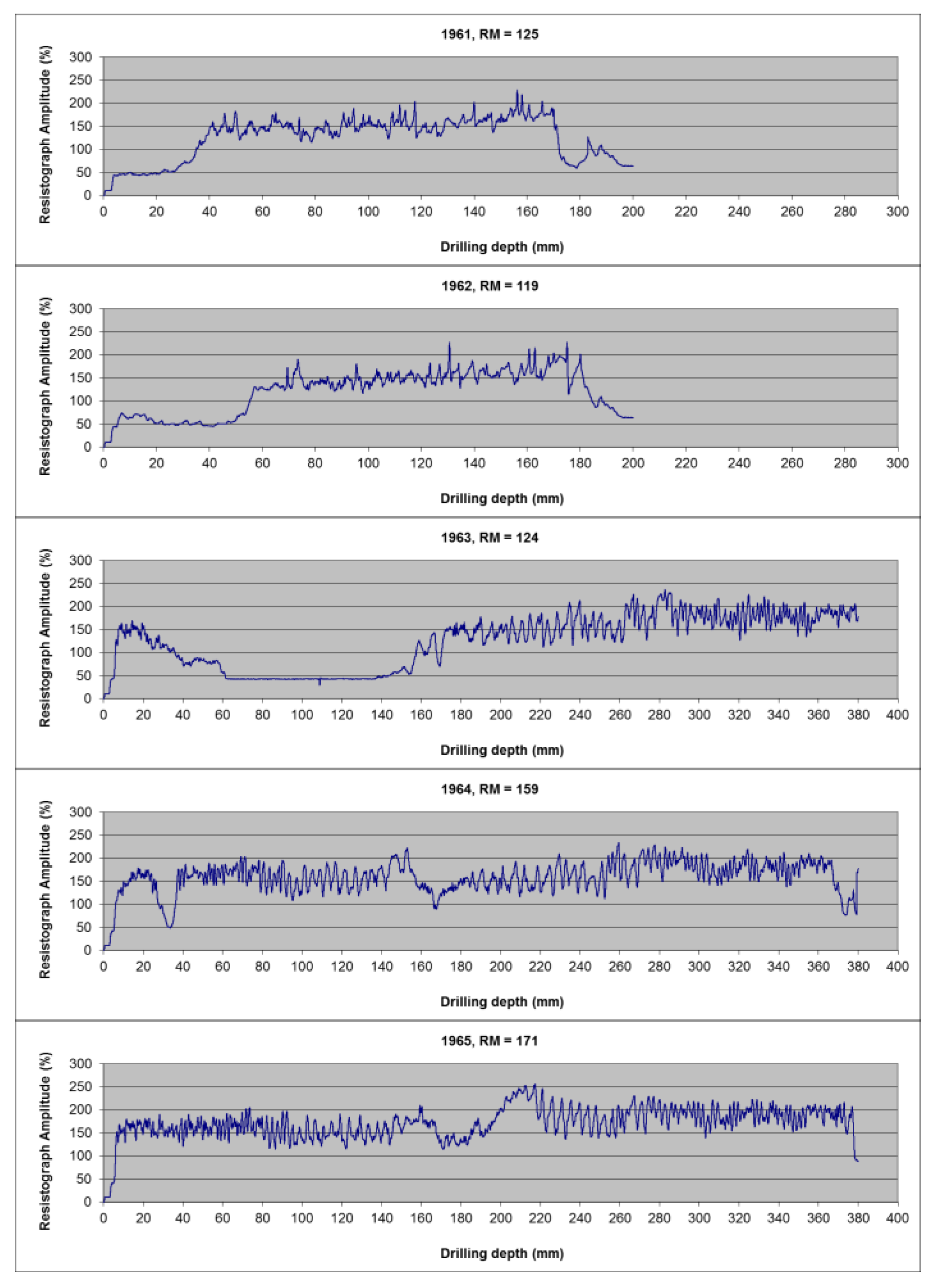
The detailed examination of selected elements of the polygonal barn for the purposes of the case study was performed using resistance drilling, which is based on measuring the resistance to penetration of a small drill bit through the material examined. The device used, Rinntech Resistograph 4453-S, provides data about the internal state of the element. Due to the minimal damage to the material, this is a semi-destructive method of testing the condition of timber structures [34]. The resistance drill Resistograph measures the energy required to maintain a constant speed of the drill when drilling through the material. Resistograph measures the energy required to maintain a constant speed of the drill when drilling through the material (see Figure 3). The peaks in the graph correspond to higher energy, i.e., higher resistance and higher density, while lower points are associated with lower energy, i.e., lower resistance and lower density [10]. Figure 3 shows the graphic records from the individual measurement points. The extent of the damage was determined by measuring perpendicular to the longitudinal axis of the beams. Each measuring point was recorded in the scheme of the element estimated (Figure 4). Based on resistance characteristics (RM), calculated from the area under the curve and the drilling depth, the extent of the rot was determined.
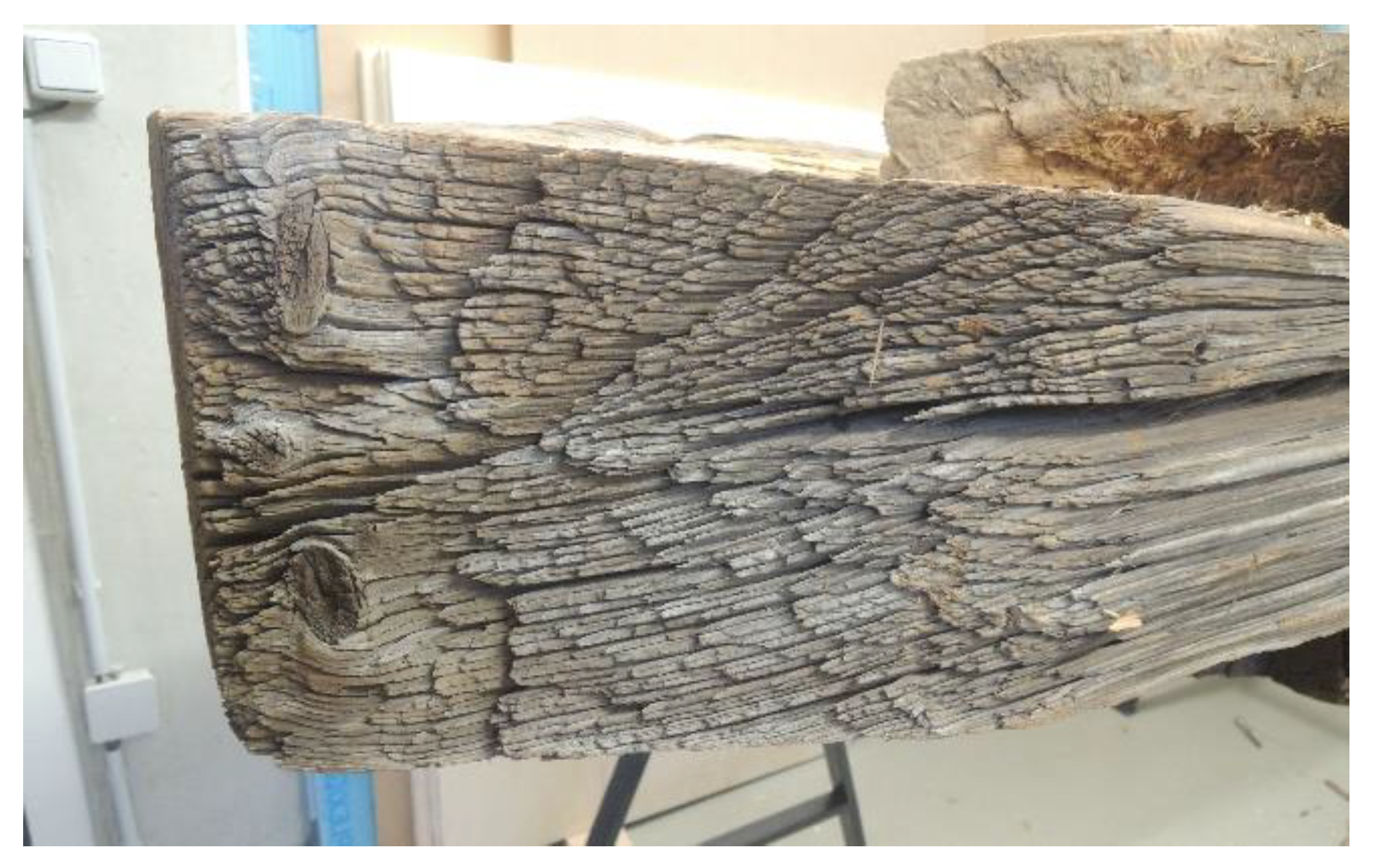
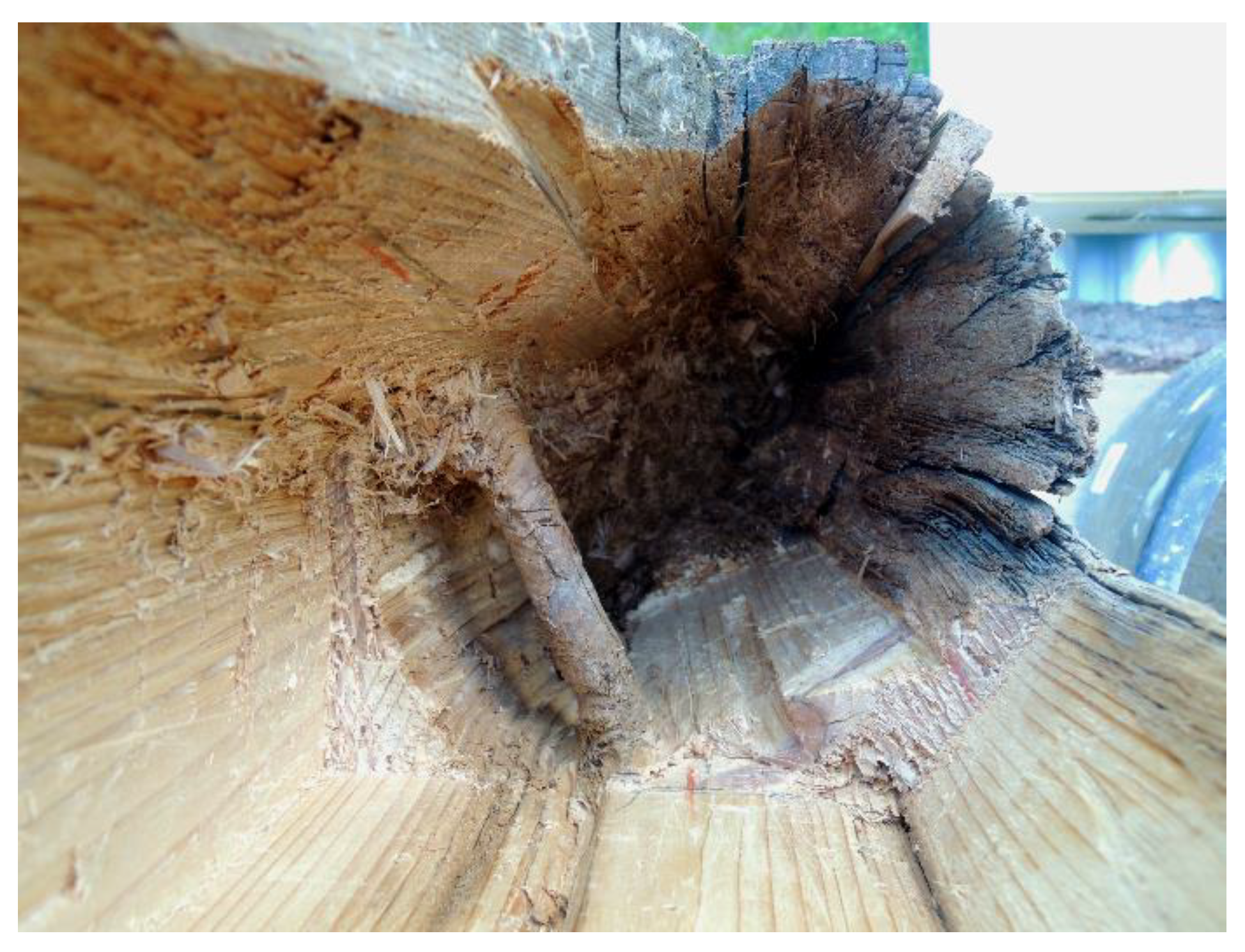
Before the repair, the damaged spot was also thoroughly visually mapped, photographed, and captured in a drawing (Figure 5). Natural defects (knots and drying checks) played an essential role when designing the repair. Although knots can play a different role when in different places in the beam and under different load conditions, here the role of knots was positive; by contrast, checks had a negative effect. For example, a ring of knots in the beam ends ensured integrity near the rotting (Figure 6), since only shear loading can be expected here. Additionally, the knot between the mortises of the double-sided dovetails also provided integrity (Figure 6). The checks in the centre of the element restricted the possible preservation of a large part of the profile and the damaged portion had to be removed up to the check (Figure 6).
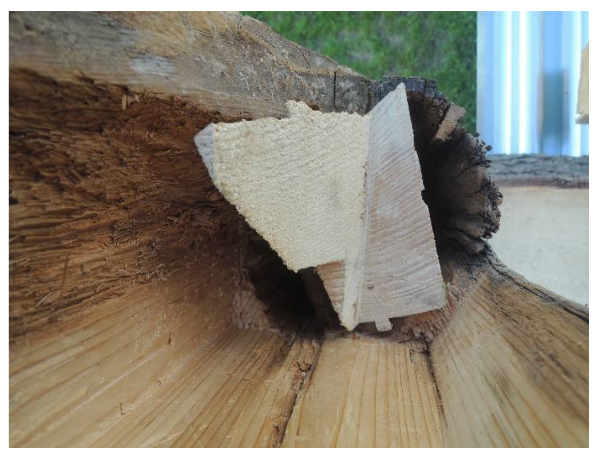
Inserting a new part by a ledge joint became the central idea of inserting a new short piece of wood into the damaged bottom (Figure 7 and Figure 8). On the other hand, a check was made use of when the ledge was secured by a wedge (Figure 9). The top surface of the pillar laid down (Figure 9) shows the sensitive connection of the inserted new part in the place of the drying check. The gentle structural solution was repeated in the place of a double-sided dovetail lap joint (Figure 10), which provides an overlap and, thus, a visually more pleasant view.
The material was selected so that the tree rings corresponded with the orientation of the tree rings of the repaired beam. The material was naturally dried before use to a moisture content of less than 20%, thereby eliminating shape and dimensional deformations, which are undesirable after installation. In the case of the lower damaged part of the column, oak was chosen as a repair material due to its better resistance to increased moisture stress in the sill part and due to better homogeneity, which was needed for this very short and highly shaped insert. The same material was used to repair the belfry of the White Tower in Hradec Králové [35]. The total time to repair the beam was 30 h of work.
4. Beam (H2) Diagnosis and Repair Design
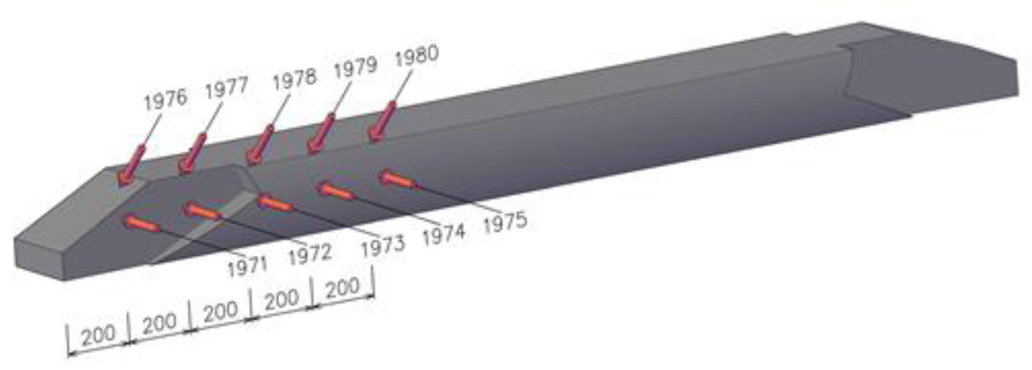
Another design of structural repair focused on beam (H2), i.e., a part of the polygonal wall damaged by central rot in the location of a dovetail joint. The main objective was to change the damaged element as little as possible and, if possible, not to interfere with the front (visible) surface of the beam. As in the previous case, a detailed examination was performed using resistance drilling. Figure 11 shows the graphic records from the individual measurement points. The extent of the damage was determined by measuring perpendicular to the longitudinal axis of the beams. Each measuring point was recorded in the scheme of the element estimated (Figure 12). Based on resistance characteristics (RM) calculated from the area under the curve and the drilling depth, the extent of the rot was determined.
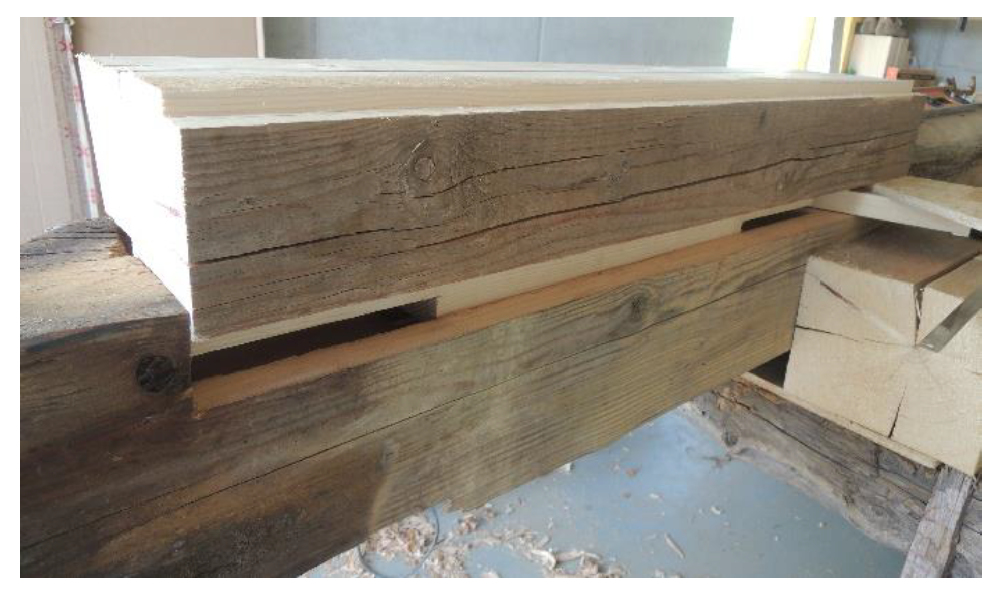
Before the repair, the damaged spot was also thoroughly visually mapped, photographed (Figure 13), and captured in a drawing (Figure 14). Natural defects (knots and drying checks) played an essential role when designing the repair. The role of knots was positive; by contrast, checks had a negative effect. A knot in the sloping end ensured integrity near the rotting, between two drying checks (Figure 15). Due to the checks converging towards the element centre, the sloping beam end could not be preserved in its entire profile, and the damaged section between the checks also had to be removed. This partially breached the request for no interference with the external surfaces of the element repaired. In case of surface damage, the beam end integrity was ensured by a knot on the opposite side of the joint. The knot in the hole in the central part of the beam served as a reinforcing element; therefore, it was fully preserved (Figure 16).
The insert filling the surface of the dovetail joint was shaped exactly by the longitudinal and transversal surfaces formed by the removal of the rot from the damaged part of the beam (Figure 17). The insert was fixed by oak pins. The rear insert was inserted into the prepared grooves providing fixed position of the insert in the cleaned hole and thus stabilization of the thin superficial preserved part of the beam (Figure 18). Figure 19 shows the entire view of the repaired dovetail joint of the damaged beam, with inserts respecting the drying check, i.e., the area of the dovetail joint. Figure 20 shows the repaired beam back in its position in the timber wall of the barn, manifesting the visually gentle structural solution.
The material for the production of the inserts was selected so that the tree rings correspond with the orientation of the tree rings of the repaired beam (Figure 19). The material for the inserts was naturally dried before use to a moisture content of less than 20%, thereby eliminating shape and dimensional deformations, which are undesirable after installation. The material for the structural repair was the originally used spruce of strength class C20. The rotten-out space around the rear insert (Figure 18) was left without structural repair. Before the insert was put in place, the rotten space was spread with clay mortar with addition of lime, curd cheese, and chopped wheat straw (Figure 19). The preparation and properties of the clay mortar are described in detail in Section 6. The total time to repair the beam was 27 h of work.
5. Beam (I2) Diagnosis and Repair Design
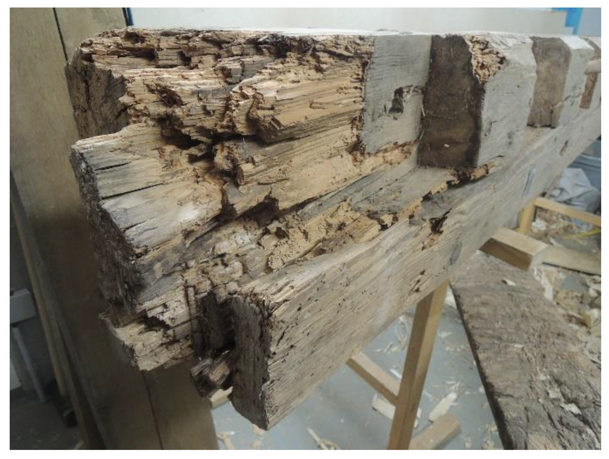
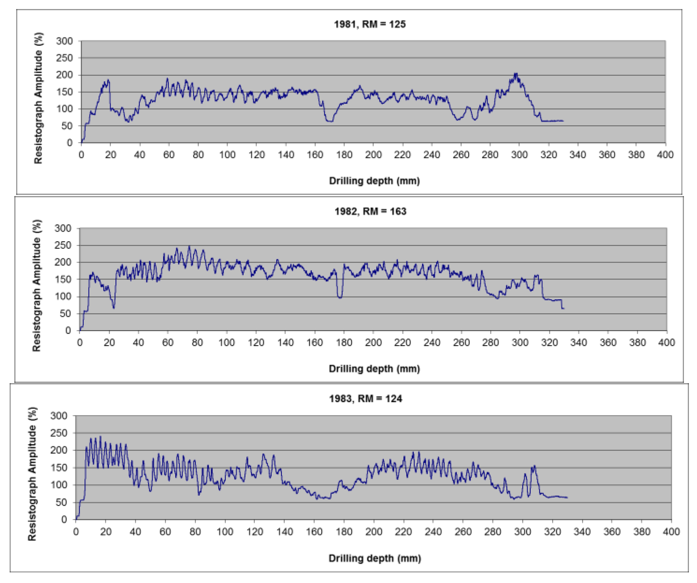
The third design of structural repair to be presented focused on beam (I2), i.e., a part of the polygonal wall damaged by central rot in the location of a dovetail joint. Again, the main objective was to change the damaged element as little as possible and, if possible, not to interfere with the front (visible) surface of the beam. With regard to the extent of the damage, this request seemed almost unrealistic, and in the common repair of a monument, such an element would be replaced in its entire profile. As in the previous case, a detailed examination was performed using resistance drilling. Figure 21 shows the graphic records from the individual measurement points. The extent of the damage was determined by measuring perpendicular to the longitudinal axis of the beams. Each measuring point was recorded in the scheme of the element estimated (Figure 22). Based on resistance characteristics (RM), calculated from the area under the curve and the drilling depth, the extent of the rot was determined.
Before the repair, the damaged spot was thoroughly visually mapped (Figure 23) and captured in the drawing (Figure 24). The role of knots was positive; by contrast, checks had a negative effect. The knot in the joint end ensured integrity near the rotting (Figure 23 and Figure 25). Due to the checks converging towards the element centre, the sloping beam end could not be preserved in its entire profile, and the damaged section between the checks also had to be removed. However, the new wood addition to the beam was of a minimum extent (Figure 26). The space where a new part had to be inserted was enclosed in two ends (Figure 27), which could be partially sawed, and the remaining end plane had to be formed by gradual chiseling. Figure 28 documents the gradual formation of the bed for insert with several levels. The insert had to be fitted into the precisely defined longitudinal space (Figure 29), which made the formation significantly more complicated as no additional modifications were possible.
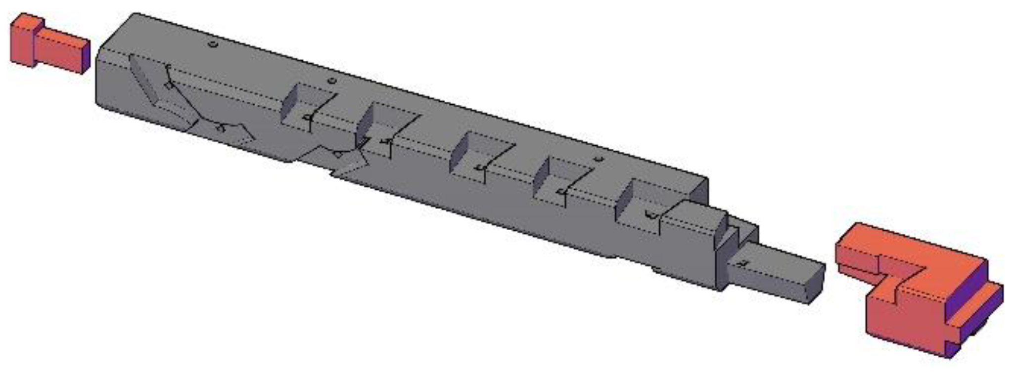
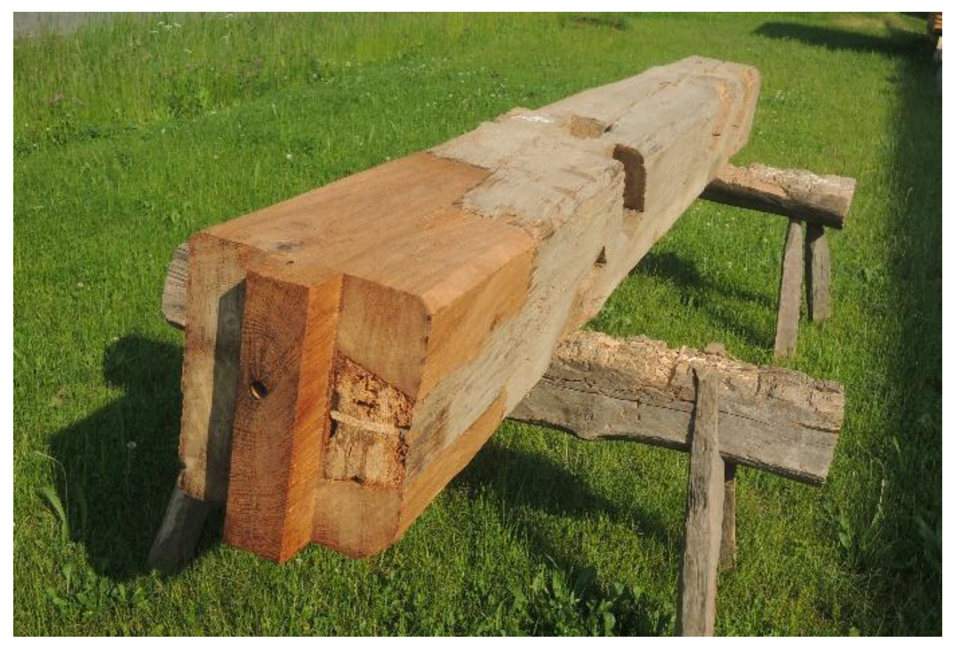
The insert filling the surface of the dovetail joint was shaped exactly by the longitudinal and transversal surfaces formed by the removal of the rot from the damaged part of the beam (Figure 30). The insert was fixed by oak pins. The following figures show the entire view of the repaired dovetail joint, finished with the insert fitted (Figure 31), the repaired beam put back in its place in the barn timber wall (Figure 32), including the detail of the outside view of the timber wall (Figure 32), manifesting the very sensitive structural solution.
The material for the production of the insert was selected so that the tree rings correspond with the orientation of the tree rings of the repaired beam (Figure 31). The material for the insert was naturally dried before use to a moisture content of less than 20%, thereby eliminating shape and dimensional deformations, which are undesirable after installation. The material for the structural repair was the originally used spruce of strength class C20. The rotten out space around the back of the insert (Figure 25) was left without structural repair. Before the insert was put in place, the rotten space was spread with clay mortar with the addition of lime, casein, and chopped wheat straw. The total time to repair the beam was 40 h of work.
6. Preparation and Properties of Earth-Based Mortars for Cavity Filling
Traditional building techniques often used mixtures of local clayey soils with different mineralogical and granulometric compositions [36] to produce building material for a specific function. The use of earth-based mortars to fill the cavities remaining after constructional repair was inspired by the ancient rural tradition, in which drying checks were spread over with manure and an admixture of chopped straw and clayey soil. For the purpose of experimental testing of the filling mixtures, three versions of earth-based mortar with different compositions were designed based on traditional materials: clayey soil, chopped wheat straw, lime, and curd cheese.
6.1. Preparation of Clay Mortars
The earth-based material used in our study for the production of all tested mortars was a ready mixed dry product available on the market and intended for the preparation of earth-based mortars or plasters. The product with the trade name Picas Econom [37] consists of natural soil with an admixture of sand and organic fibers (chopped straw), according to the manufacturer’s information.
Within the experiment, we identified the mineralogical and granulometric composition of this commercial product. Minerals were determined by the X-ray diffraction method (XRD), and a sieve test revealed the distribution of grains’ size. The XRD results are given in Table 1 and the results of performed granulometry in Figure 33.
In addition to the Picas ready mixed dry product itself (E), two other mortars enriched with admixtures were designed and tested: mortar with the addition of lime (CL) and mortar with the addition of lime and casein (CLC). The lime was added in the Picas mixture in the form of lime putty. The casein was added in the form of curd cheese, mixed into the lime putty. The composition of the experimental mortars is provided in Table 2 and the appearance of hardened mixtures is documented in Figure 34.
The mortars were used to form beams, with dimensions 40 × 40 × 160 mm, which were then stored at 22 °C and RH 60%. After 100 days, the beams of hardened mortars were subjected to mechanical tests and the linear and volumetric shrinkage were determined. For other tests, modified parts of the beams for each test were used.
6.2. Methods of Testing Raw Material and Mortars
A sample of the earth-based product Picas was homogenized, and an aliquot for XRD was mechanically finely grounded. Data were collected in the angular range 5–70° 2 theta with a Bruker Advance diffractometer in Bragg Brentano geometry adopting Cu radiation generated at 40 kV and 30 mA. The XRD quantitative phase analysis was performed with SOFTWARE TOPAS 4.2, implementing the Rietveld method.
The mechanical properties of the prepared experimental mortars were characterized by bending strength under concentrated load according to EN 12,372 [38] and strength under simple pressure EN 1926 [39]. The strength under simple pressure test was carried out using halves of the 40 × 40 × 160 mm beams obtained after the bending strength test. The resulting strength value was calculated as an average of five parallel measurements.
Linear shrinkage was calculated from the formula:
where lf is the inner length of the mould used and l is the length of the dried specimen.
The volumetric shrinkage was calculated from the formula:
where Vf is the internal volume of the mould used and V is the volume of the dried specimen. The value of open porosity, bulk density, and pore size distribution was determined using the Micromeritics AutoPore IV 9500 mercury porosimeter with a maximum mercury pressure of 228 MPa and a pore size measurement range of 0.005–360 μm. Three parallel measurements were performed for each sample.
The water vapour permeability of the mortars was determined in compliance with EN 15,803 [40] using the wet-cup testing method. The mortar samples, sized 40 × 40 × 10 mm, were fixed using plastic sealant on the test cup (Figure 35). A relative humidity of 93% (saturated KNO3 solution) was maintained inside the cup, and 55% RH (saturated NaBr solution) was kept outside the cup. Three parallel measurements were performed for each sample.
The coefficient of capillary water absorption was determined in compliance with EN 15,801 [41] for the 40 × 40 × 160 mm beam halves; due to poor consistency of the samples, their walls were coated with a mixture of micro-crystalline wax and paraffin (3:2) before the test. The drying rate test of the clay mixtures was carried out according to EN 16,322 [42] using the identical specimens as for the soaking test. After water saturation, the drying progressed freely (without forced circulation) in an environment of 40% RH (saturated solution of K2CO3) at 23 °C.
6.3. Results
- Mineralogical composition
The XRD analysis of the earth-based product Picas (E) showed that the dominant minerals are quartz (about 60% wt.) and feldspar (33% wt.). Mica or illite, amphibole, and kaolinite are found in an amount of several weight percentage. Besides mica/illite and kaolinite, no other clay minerals were detected. These are represented in the mixture with about 6% of wt. In summary, the earth-based product Picas mainly consists of quartz and feldspar with an admix of clay minerals, mainly non-expandable types of clay minerals.
- Grain size distribution
The sieve analysis of the earth-based product Picas (E) showed that grains of medium to coarse sand, sized 0.25–2 mm, dominated in the mixture (with about 80% of wt.). Larger grains, over 2 mm, are represented in a quantity of about 10% wt. Similarly, the finer components—dust and clay—are significantly less represented than sand, at about 10% wt. Sand grains were more frequently sharp, and to a lesser extent, they were semi-rounded. The organic component of the Picas product consists of chopped wheat straw, with pieces up to 34 mm in length.
- Physical properties
The values obtained for the physical properties of the hardened experimental mortars are given in Table 3.
The measured values show that the addition of lime putty in the earth-based mortar reduced the bulk density slightly; by contrast, in the mortar version with lime putty and casein, it decreased by 14,4%. The decrease in bulk density of the modified mixtures is caused by the lower density of lime putty and curd cheese compared to soil. The opposite trend can be observed in the porosity values measured as they increased in the E-EL-ELC series. The porous system of the ELC formula differs significantly, as evidenced by the pore size distribution graph (Figure 36). The mortar modified with lime and casein contains significantly more pores in the area of 10–100 µm compared to the mortar without casein.
The values of linear shrinkage of all three mixtures are comparable, but the volume shrinkage of the ELC mixture is several times greater than in the other two types of mortar.
- Mechanical properties
Bending and pressure strength tests show (Figure 37) that the addition of lime in the clay plaster reduces the mechanical properties by approximately 30% compared to the clay itself. By contrast, the mortar with lime-casein putty demonstrated an increase in strength and bending and compression of 177% and 85%, respectively, compared to mortar without LC modifications.
Regarding the stiffness compatibility of the materials, it should be noted that we expect the Young’s modulus of oak to be approximately 13 GPa [43]. When we look at the mortars, even though we do not consider them to have any structural function, we can conclude that the stiffness is relatively well tuned to be similar (not an order in magnitude as with glue), say 4 GPa. When we consider the values in bending stiffness, they follow the same trend as with strength and the one made with casein is the strongest one.
- Hygric properties
Since the tested materials are meant to seal a wooden beam, it is advisable to know their behaviour in interaction with water or water vapours to assess the compatibility of the earth-based filling with the original material.
Table 4 presents the parameters of the mortars obtained by the vapour permeability test. These values show that the diffuse properties of mortar E and EL are the same. The ELC mixture is less permeable by water vapour, which was reflected in a decreased value of diffuse parameters (W, D, δp) and an increased value of the diffuse resistance factor (μ) compared to the mortar without admixtures. A value of 12.58 was measured, which is significantly higher than the value declared by the manufacturer (1.1) in the technical data sheet [37].
The transport of liquid water through the porous structure of mortar samples is described by the water absorption coefficient (WAC). However, it was not possible to finish the water absorption test by capillary action in the pure earth-based mortar samples, as they began to fall apart after a 20 min contact with water. As regards the modified formulas, their WAC values were calculated after the test completion (24 h): 8.6 kg.m−2.h−0.5 and 0.1 kg.m−2.h−0.5 for EL and ELC, respectively.
The drying rate of fully water-saturated mortar samples is expressed by the drying index. Its value depends on the test duration, so it is necessary to compare the results related to the same time. The values of the drying index of the tested mortars at a test duration of 215 h are presented in Table 5.
According to the determined drying index, the combination of ELC dries the fastest; the earth (E) and the mortar with lime (EL) have almost the same results and drying progress.
7. Discussion
Sensitive and careful structural repairs of a protected timber polygonal barn are presented in the form of three functional samples. The extent of hidden damage was investigated using a resistance micro-drill Resistograph, based on measurement procedures presented in [8,9]. Micro-drilling meets the heritage conservation requirement to minimize interference with the element assessed; additionally, it provides a reliable interpretation of wood properties (especially when looking for cavities and holes), which can be further enhanced by a higher number of drilling holes within an assessed element, as confirmed by [11,12]. The results of the diagnosis were used to estimate the damage extent caused by the biotic action of wood-destroying fungi and insects. The opinions on how to approach repairs differ immensely. For our experiment and production of functional samples, traditional woodworking procedures were chosen, including the use of hand tools, as described, e.g., in [16]. The aim was to use the same techniques and materials as had been used in the original construction. The design emphasized minimal intervention in the valuable material, which needs to be preserved to the maximum extent, especially without larger interventions in visible parts of the damaged elements. Therefore, it was not even possible to use respectful methods of repairing historical wooden structures, which include wooden lapped joints presented, e.g., in [44]. A typical example of where minimal intervention is vital is the timbered walls, where lapped joints would significantly interfere with the aesthetic impression of the historical structure. Thus, we looked for more sensitive ways of repairs in the case of hidden damage (rot cavities). These included the production of inserts or small element replacements, including the filling of small cavities using natural mixtures, such as clay mortar, presented as part of functional samples. Three different formulas have been tested to make a suitable choice of a natural mixture.
Data obtained by testing the three formulas of mortars show that earth-based mortar (E) and earth mortar with lime putty modification (EL) have very similar physical and mechanical as well as hygric properties, and that the addition of lime to the earth mortar has not significantly affected its resulting properties. However, when casein in the form of curd cheese was added to the mixture (ELC), a substantial increase in mechanical strength was observed, as well as a slight increase in pore volume, especially in the range of diameters of 10–100 µm. These are probably micro-cracks resulting from the process of the fresh mortar drying, which was also manifested by a 7% shrinkage in volume. In a potential further use of this mixture, it would be appropriate to reduce the value of volume shrinkage by reducing the mixing water content of the fresh mortar and to achieve the needed mortar consistency by an effective mixing of the fresh mortar without an excess of water. When in contact with water or water vapours, the ELC mixture also exhibits different behaviour than the E and EL formulas. The parameters related to water vapour diffusion have declined by about 30%, but the addition of casein has caused the ELC mixture to have low liquid water absorption and thus dry the fastest.
8. Conclusions
Sensitive designs of a structural repair of damaged elements in the form of functional samples serve as a case study of an appropriate way to deal with a damaged element so that the intervention is minimized with respect to the authentic value of the historical building. The damaged parts of the structural elements have been replaced by originally used wood species, and the resulting cavities were filled with an earth-based mixture with added lime and casein. This mortar mixture was chosen as the most suitable based on testing three different formulas. The addition of casein resulted in an increase in the mechanical strengths, as well as an increase in the diffuse resistance factor and linear and volume shrinkage, compared to earth alone or earth with lime. Although we do not consider the mortar to have a structural function, its stiffness is well tuned to the timber used in the filling.
The samples of structural repair shown in the article are placed in the construction of a timbered polygonal barn, which was transferred from its original place to the area of Mišík’s farm, No. 56 Trstěnice, near Litomyšl. The polygonal barn has been completely restored and is thus available to visitors of the museum in nature.
Author Contributions
Conceptualization, M.K. and D.F.; methodology, M.K., Z.S. and D.F.; software, J.K.; validation, D.F. and Z.S.; formal analysis, J.K.; investigation, M.K. and D.F.; resources, M.K., D.F. and Z.S.; data curation, J.K. and D.F.; writing—original draft preparation, M.K.; writing—review and editing, D.F., J.K. and Z.S.; supervision, D.F. and Z.S.; project administration, Z.S.; funding acquisition, Z.S. All authors have read and agreed to the published version of the manuscript.
Funding
This work has been created with state support of the Technology Agency of the Czech Republic within the Program ÉTA, project no. TL03000377 and was supported by the Czech Academy of Sciences under the research programme “Strategy AV21: 23. City as a Laboratory of Change; Construction, Historical Heritage and Place for Safe and Quality Life”.
Data Availability Statement
Not applicable.
Conflicts of Interest
The authors declare no conflict of interest.
References
- Blanchette, R.A.; Held, B.W.; Jurgens, J.A.; Haight, J.E. Wood deterioration in Chacoan great houses of the southwestern United States. Conserv. Manag. Archaeol. Sites 2004, 6, 203–212. [Google Scholar] [CrossRef]
- Reinprecht, L. Diagnostic of the degraded zones of fir be—Am situated in the st. Egidius’ basilica in Bardejov. For. Wood Technol. 2009, 67, 201–207. [Google Scholar]
- Mosoarca, M.; Gionen, V. Historical wooden structures from Banat region, Romania. Damages: Modern consolidation solutions. J. Cult. Herit. 2013, 14, 45–59. [Google Scholar] [CrossRef]
- Cavalli, A.; Togni, M. How to improve the on-site MOE assessment of old timber beams combining NDT and visual strength grading. Nondestruct. Test. Eval. 2013, 28, 252–262. [Google Scholar] [CrossRef]
- Kloiber, M.; Drdácký, M. Diagnostika Dřevěných Konstrukcí; Kniha, Informační Centrum ČKAIT: Praha, Czech Republic, 2015; ISBN 978-80-87438-64-0. [Google Scholar]
- UNI 11119:2004; Cultural Heritage—Wooden artefacts—Load-bearing structures—On Site Inspections for Diagnosis of Timber Members. Uni-Italial: Roma, Italy, 2004; (The Italian standard).
- Riggio, M.; Anthony, R.W.; Augelli, F.; Kasal, B.; Lechner, T.; Muller, W.; Tannert, T. Recommendation of RILEM TC 215-AST: In situ assessment of structural timber using non-destructive techniques. Mater. Struct. 2014, 47, 749–766. [Google Scholar] [CrossRef]
- Tannert, T.; Anthony, R.; Kasal, B.; Kloiber, M.; Piazza, M.; Riggio, M.; Rinn, F.; Widmann, R.; Yamaguchi, N. Recommendation of RILEM TC 215-AST: In-situ assessment of structural timber using semi-destructive techniques. Mater. Struct. 2014, 47, 767–785. [Google Scholar] [CrossRef]
- Dietsch, P.; Köhler, J. Assessment of Timber Structures; Shaker Verlag: Aachen, Germany, 2010; p. 134. [Google Scholar]
- Kloiber, M.; Drdácký, M.; Machado, J.S.; Piazza, M.; Yamaguchi, N. Prediction of mechanical properties by means of semi-destructive methods: A review. Constr. Build. Mater. 2015, 101, 1215–1234. [Google Scholar] [CrossRef] [Green Version]
- Sharapov, E.; Brischke, C.; Militz, H.; Smirnova, E. Combined effect of wood moisture content, drill bit rotational speed and feed rate on drilling resistance measurements in Norway spruce (Picea abies (L.) Karst.). Wood Mater. Sci. Eng. 2020, 15, 198–204. [Google Scholar] [CrossRef]
- Jaskowska-Lema’nska, J.; Przesmycka, E. Semi-Destructive and Non-Destructive Tests of Timber Structure of Various Moisture Contents. Materials 2021, 14, 96. [Google Scholar] [CrossRef]
- Feio, A.; Machado, J.S. In-situ assessment of timber structural members: Combining information from visual strength grading and NDT/SDT methods—A review. Constr. Build. Mater. 2015, 101, 1157–1165. [Google Scholar] [CrossRef]
- Nowak, T.P.; Jasieńko, J.; Czepiżak, D. Experimental tests and numerical analysis of historic bent timber elements reinforced with CFRP strips. Constr. Build. Mater. 2013, 40, 197–206. [Google Scholar] [CrossRef]
- Coradi, M.; Borri, A. Fir and chestnut timber beams reinforced with GFRP pultruded elements. Compos. Part B Eng. 2007, 38, 172–181. [Google Scholar] [CrossRef]
- Bertolini, M.S.; Macedo, L.B.; Almeida, D.H.; Icimoto, F.H.; Rocco Lahr, F.A. Restoration of structural timber elements using epoxy resin: Analysis of mechanical properties. In Structural Health Assessment of Timber Structures, Book Series: Advanced Materials Research; Trans Tech Publications Ltd.: Bäch SZ, Switzerland, 2013; Volume 778, pp. 582–587. ISSN 1022-6680. [Google Scholar]
- Larsen, K.E.; Marstein, N. Conservation of Historic Timber Structures: An Approach; Butterworth-Heinemann: Oxford, UK, 2000; p. 140. [Google Scholar]
- Kunecký, J.; Fajman, P.; Hasníková, H.; Kuklík, P.; Kloiber, M.; Sebera, V.; Tippner, J. Lapped Scarf Joints for Reconstruction of Historical Structures; Institute of Theoretical and Applied Mechanics AS CR, v. v. i.: Praha, Czech Republic, 2016; p. 72. ISBN 978-80-86246-70-3. [Google Scholar]
- Pumpelly, R. Explorations in Turkestan; Michigan State University: East Lansing, MI, USA, 1908; p. 494. [Google Scholar]
- European Convention for the Protection of Archaeological Safety (revised), drawn up in La Valetta on January 16, 1992. J. Laws 1996, 120, 564.
- Maddison, M.; Mauring, T.; Kirsimäe, K.; Mander, U. The humidity buffer capacity of clay—Sand plaster filled with phytomass from treatment wetlands. Build. Environ. 2009, 44, 1864–1868. [Google Scholar] [CrossRef]
- Liuzzi, S.; Hall, M.R.; Stefanizzi, P.; Casey, S.P. Hygrothermal behaviour and relative humidity buffering of unfired and hydrated lime-stabilised clay composites in a Mediterranean climate. Build. Environ. 2013, 61, 82–92. [Google Scholar] [CrossRef]
- Lima, J.; Faria, P.; Santos Silva, A. Earthen plasters based on illitic soils from Barrocal region of Algarve: Contributions for building performance and sustainability. Key Eng. Mater. 2016, 678, 64–77. [Google Scholar] [CrossRef]
- Faria, P.; Silva, V.; Jamú, N.; Dias, I.; Gomes, M.I. Evaluation of air lime and clayish earth mortars for earthen wall renders. In Vernacular Heritage and Earthen Architecture. Contributions for Sustainable Development; CRC Press: Boca Raton, FL, USA; Taylor & Francis Group: Oxfordshire, UK, 2013; pp. 407–413. [Google Scholar]
- Ashurst, J.; Ashurst, N. Pratical Building Conservation: Brick, Terracotta & Earth, Volume 2. English Heritage Technical Handbook; Gower Technical Press: Hampshire, UK, 1995; p. 1020. [Google Scholar]
- Minke, G. Building with Earth—Design and Technology of a Sustainable Architecture; Publishers for Architecture; Birkhäuser: Basel, Switzerland, 2006; p. 199. [Google Scholar]
- Žabičková, I. Hliněné Stavby; Era Vydavatelství: Brno, Czech Republic, 2002. [Google Scholar]
- ICOMOS, ISCARSAH: Principles for the Conservation of Wooden Built Heritage Adopted by the 19th ICOMOS General Assembly, New Delhi, India. 2017. Available online: http://iiwc.icomos.org/papers.html#documents (accessed on 1 January 2021).
- Melin, K. Techniques of Cleaving Wood with an Axe and Mallet. In Building Histories: The Processing of the Fourth Annual Construction History Society Conference; Construction History Society: Cambridge, UK, 2017; pp. 89–100. [Google Scholar]
- Drdacký, M.; Mlázovský, V.; Růžička, P. Historic Carpentry in Europe: Discoveries and Potential. APT Bull. 2004, 35, 33–41. [Google Scholar] [CrossRef]
- Almevik, G.; Melin, K. Traditional Craft Skills as a Source of Historical Knowledge. Mirator 2015, 16, 72–102. [Google Scholar]
- Høgseth, H. The language of craftsmanship. In Embodied Knowledge: Historical Perspectives on Technology and Belief; Oxbow: Oxford, UK, 2013; pp. 95–105. [Google Scholar]
- McCaig, I.; Ridout, B. Practical Building Conservation: Timber; Ashgate: Farnham, UK, 2012. [Google Scholar]
- Nowak, T.P.; Jasieńko, J.; Hamrol-Bielecka, K. In situ assessment of structural timber using the resistance drilling method—Evaluation of usefulness. Constr. Build. Mater. 2016, 102, 403–415. [Google Scholar] [CrossRef]
- Kloiber, M.; Bláha, J.; Václavík, F.R.; Růžička, P.; Kunecký, J. Modern D;Iagnostic Methods and Traditional Carpentry Techniques Used for the Renovation of the White Tower Belfry in Hradec Kralove; SHATIS: Wroclaw, Poland, 2015; pp. 260–271. ISSN 0860-2395. [Google Scholar]
- Slížková, Z.; Gruber, M.; Kostkanová, V.; Frankeová, D.; Wimmer-Frey, I.; Drdácký, M. Soils and Earthen Building Materials Used for the Buddhist Temple Complex. Int. J. Arch. Heritage 2014, 10, 406–417. [Google Scholar] [CrossRef]
- Picas ECONOM. Available online: https://www.picas.cz/picas-econom-hruba/ (accessed on 6 September 2022).
- EN 12372:2006; Natural Stone Test Methods—Determination of Flexural Strength under Concentrated Load. British Standards Institution: London, UK, 2006.
- EN 1926:2006; Natural Stone Test Methods—Determination of Uniaxial Compressive Strength. British Standards Institution: London, UK, 2006.
- EN 15803:2009; Conservation of Cultural Property—Test methods—Determination of Water Vapour Permeability (δp). British Standards Institution: London, UK, 2009.
- EN 15801:2009; Conservation of Cultural Property—Test methods—Determination of Water Absorption by Capillarity. British Standards Institution: London, UK, 2009.
- 42. EN 16322:2013; Conservation of Cultural Heritage—Test methods—Determination of Drying Properties. British Standards Institution: London, UK, 2013.
- Požgaj, A.; Chovanec, D.; Kurjatko, S.; Babiak, M. Štruktúra a Vlastnosti Dreva (Structure and Properties of Wood), 1st ed.; Príroda: Bratislava, Slovakia, 1993; p. 485. ISBN 80-07-00600-1. [Google Scholar]
- Kunecký, J.; Hasníková, H.; Kloiber, M.; Milch, J.; Sebera, V.; Tippner, J. Structural assessment of a lapped scarf joint applied to historical timber constructions in central Europe. Int. J. Arch. Heritage 2018, 12, 666–682. [Google Scholar] [CrossRef]
Figure 1.
Polygonal timbered barn before dismantling.

Figure 2.
Damage to beam (III) at the bottom.

Figure 3.
Graphic records from the individual points of measurement by Resistograph, beam (III), measured parallel to the orientation of the pin at the bottom of the beam.
Figure 3.
Graphic records from the individual points of measurement by Resistograph, beam (III), measured parallel to the orientation of the pin at the bottom of the beam.


Figure 4.
Marking of the points measured by Resistograph, beam (III).

Figure 5.
A scheme of the rot extent, beam (III), (yellow—replacement, blue—reduced wood density without the need for repair, grey—standard wood density without the need of repair). Arrow and + marking points measured with Resistograph.
Figure 5.
A scheme of the rot extent, beam (III), (yellow—replacement, blue—reduced wood density without the need for repair, grey—standard wood density without the need of repair). Arrow and + marking points measured with Resistograph.

Figure 6.
Gradual removal of the damaged wood at the beam bottom (after cleaning).

Figure 7.
A 3D model beam (III) drawing of the structural repair of the damaged beam.

Figure 8.
The new part before being inserted by a ledge joint.

Figure 9.
The bottom of the damaged beam (III) after the repair, including the ledge joint secured by a wedge placed in the drying check.
Figure 9.
The bottom of the damaged beam (III) after the repair, including the ledge joint secured by a wedge placed in the drying check.

Figure 10.
The bottom of the damaged beam (III) after the repair.

Figure 11.
Graphic records from the individual points of measurement by Resistograph, beam (H2), measured parallel to the orientation of the pin at the bottom of the beam.
Figure 11.
Graphic records from the individual points of measurement by Resistograph, beam (H2), measured parallel to the orientation of the pin at the bottom of the beam.

Figure 12.
Marking of the points measured by Resistograph, beam (H2).

Figure 13.
Damage to the beam (H2) in the location of the dovetail joint.

Figure 14.
A scheme of the extent of rot, beam (H2) (yellow—replacement, grey—standard wood density without need of repair). Arrow and + marking points measured with Resistograph.
Figure 14.
A scheme of the extent of rot, beam (H2) (yellow—replacement, grey—standard wood density without need of repair). Arrow and + marking points measured with Resistograph.

Figure 15.
Detail of the damaged beam end before the repair, the end integrity ensured by the knot near the drying check.
Figure 15.
Detail of the damaged beam end before the repair, the end integrity ensured by the knot near the drying check.

Figure 16.
Detail of the cleaned hole in the central part of the beam, including the grooves for the rear insert.
Figure 16.
Detail of the cleaned hole in the central part of the beam, including the grooves for the rear insert.

Figure 17.
A 3D model beam (H2) drawing of the structural repair of the damaged beam.

Figure 18.
The rear insert fixed in the grooves.

Figure 19.
Dovetail joint of the damaged timber beam (H2) after the repair.

Figure 20.
The repaired beam put back to its original place in the barn timber wall.

Figure 21.
Graphic records from the individual measurement points using the Resistograph drill, beam (I2), measured vertically in the centre of the element.
Figure 21.
Graphic records from the individual measurement points using the Resistograph drill, beam (I2), measured vertically in the centre of the element.


Figure 22.
Marking of the points measured by Resistograph, beam (I2).

Figure 23.
Damage to the beam (I2) in the location of the dovetail joint.

Figure 24.
A scheme of the extent of the rot, beam (I2) (yellow—replacement, grey—standard wood density without the need of repair). Arrow and + marking points measured with Resistograph.
Figure 24.
A scheme of the extent of the rot, beam (I2) (yellow—replacement, grey—standard wood density without the need of repair). Arrow and + marking points measured with Resistograph.

Figure 25.
Detail of a hole left in the end of the damaged beam after the cleaning.

Figure 26.
The repaired beam put back to its original place in the barn timber wall (outside view).

Figure 27.
Finally cleaned part of the damaged beam.

Figure 28.
The gradual formation of the bed for the insert copying the damage area.

Figure 29.
Formation of the insert and the gradual fitting.

Figure 30.
A 3D model beam (I2) drawing of the structural repair of the damaged beam.

Figure 31.
Dovetail joint of the damaged timber beam (I2) after the repair.

Figure 32.
The repaired beam put back to its original place in the barn timber wall (inside view).

Figure 33.
Granularity of ready mixed earth-based dry product.

Figure 34.
The appearance of hardened mixtures (halves of 4 × 4 × 16 cm beams) on the surface and in the cross section, E—left, EL—middle, ELC—right.
Figure 34.
The appearance of hardened mixtures (halves of 4 × 4 × 16 cm beams) on the surface and in the cross section, E—left, EL—middle, ELC—right.

Figure 35.
Arrangement of the water vapour permeability test.

Figure 36.
Distribution of pore size of the hardened mortars.

Figure 37.
Mechanical strengths of the hardened mortars (left) and Young’s modulus in bending (right).
Figure 37.
Mechanical strengths of the hardened mortars (left) and Young’s modulus in bending (right).


Table 1.
XRD quantitative analysis of ready mixed earth-based dry product.
| Phase | wt. % |
|---|---|
| Quartz | 59.7 ± 0.6 |
| K-feldspar | 19.3 ± 0.5 |
| Na-feldspar | 13.8 ± 0.3 |
| Mica/Illite | 4.4 ± 0.2 |
| Amphiboles | 1.5 ± 0.2 |
| Kaolinite | 1.4 ± 0.2 |
Table 2.
Formulas of the tested mortars, in parts of volume.
| Marked as. | Earth-Based Mixture E | Water | Lime L | Curd Cheese C |
|---|---|---|---|---|
| E | 8 | 1 | - | - |
| EL | 8 | * | 1 | - |
| ELC | 8 | * | 0.5 | 0.5 |
* minimum amount of water necessary to gain consistency suitable for filling cavities. E Picas Econom earth-based ready mixture. L (lime)—lime putty prepared by slaking of lump lime produced by. Vitošov Lime Plant s.r.o. (CaO 97.5%, MgO 0.6%, SiO2 1.6%). C (hard curd cheese)—trade name: Jaroměřický tvrdý tvaroh na strouhání (hard curd for grating).
Table 3.
Physical properties of hardened mortars.
| Mortar | Bulk Density [kg/m3] | Linear Shrinkage [%] | Volumetric Shrinkage [%] | MIP Porosity [%] |
|---|---|---|---|---|
| E | 1728 ± 35 | 2.5 ± 0.4 | 1.2 ± 0.5 | 24.6 ± 1.59 |
| EL | 1643 ± 9 | 1.2 ± 0.2 | 1.8 ± 0.3 | 27.4 ± 1.95 |
| ELC | 1479 ± 58 | 2.2 ± 1.0 | 7.0 ± 2.3 | 29.33 ± 3.25 |
Table 4.
Results of the vapour permeability test of hardened mortars.
| Mortar | Vapour Permeability W [-] | Diffuse Resistance Factor (μ) [-] | Water Vapour Diffusion Coefficient (D) [m2s−1] | Diffusion Conductivity Coefficient (δ p) [kg·m−1·s−1·Pa−1] |
|---|---|---|---|---|
| E | 1.59·10−9 ± 3.77·10−11 | 12.58 ± 0.30 | 2.11·10−6 ± 5.26·10−8 | 0.015·10−9 ± 3.16·10−13 |
| EL | 1.61·10−9 ± 2.03·10−11 | 12.57 ± 0.18 | 2.12·10−6 ± 3.04·10−8 | 0.015·10−9 ± 1.82·10−13 |
| ELC | 1.22·10−9 ± 4.23·10−11 | 16.49 ± 0.79 | 1.61·10−6 ± 6.22·10−8 | 0.011·10−9 ± 4.23·10−13 |
Table 5.
Results of drying test (drying index).
| Sample | Drying Index [-] |
|---|---|
| E | 0.77 ± 0.02 |
| EL | 0.79 ± 0.01 |
| ELC | 0.47 ± 0.04 |
Disclaimer/Publisher’s Note: The statements, opinions and data contained in all publications are solely those of the individual author(s) and contributor(s) and not of MDPI and/or the editor(s). MDPI and/or the editor(s) disclaim responsibility for any injury to people or property resulting from any ideas, methods, instructions or products referred to in the content. |
© 2023 by the authors. Licensee MDPI, Basel, Switzerland. This article is an open access article distributed under the terms and conditions of the Creative Commons Attribution (CC BY) license (https://creativecommons.org/licenses/by/4.0/).
Share and Cite
MDPI and ACS Style
Kloiber, M.; Frankeová, D.; Slížková, Z.; Kunecký, J. Repair of Old Timber Log House Using Cavity Filling with Compatible Natural Materials. Buildings 2023, 13, 550. https://doi.org/10.3390/buildings13020550
AMA Style
Kloiber M, Frankeová D, Slížková Z, Kunecký J. Repair of Old Timber Log House Using Cavity Filling with Compatible Natural Materials. Buildings. 2023; 13(2):550. https://doi.org/10.3390/buildings13020550
Chicago/Turabian StyleKloiber, Michal, Dita Frankeová, Zuzana Slížková, and Jiří Kunecký. 2023. "Repair of Old Timber Log House Using Cavity Filling with Compatible Natural Materials" Buildings 13, no. 2: 550. https://doi.org/10.3390/buildings13020550
Note that from the first issue of 2016, this journal uses article numbers instead of page numbers. See further details here.