Photogrammetric Documentation of Stone Surface Topography Changes as a Tool in Conservation Praxis


1
Department of Geomatics, Faculty of Civil Engineering, Czech Technical University in Prague, Thákurova 7, 166 29 Prague, Czech Republic
2
Department of Geotechnics, Faculty of Civil Engineering, Czech Technical University in Prague, Thákurova 7, 166 29 Prague, Czech Republic
3
Institute of Theoretical and Applied Mechanics, Czech Academy of Science, Prosecká 809/76, 190 00 Prague, Czech Republic
*
Author to whom correspondence should be addressed.
Buildings 2023, 13(2), 439; https://doi.org/10.3390/buildings13020439
Submission received: 2 December 2022
/
Revised: 20 January 2023
/
Accepted: 2 February 2023
/
Published: 6 February 2023
(This article belongs to the Section Building Materials, and Repair & Renovation)
Abstract
:Traces of stone working are an integral part of natural stone objects and artefacts of historical value. Each preserved trace does not only carry a value in determining the type of tool used, but also provides information about the historic stonemason’s work process and technology. For this reason, it is desirable to assess the restoration method’s influence on the change in surface topography. The effect of restoration interventions was investigated on five stone artefacts, three of ‘opuka’, one of sandstone and one of limestone, four of which showed historic working traces. For this purpose, selected restoration methods—chemical, mechanical and laser—were used. The examined artefacts were accurately photogrammetrically captured before and after the restoration interventions in order to assess and evaluate changes in the degree of preservation of the traces. Fine results using common tools were achieved in terms of geometric quality, level of detail and the documentation’s predictive power. The models’ geometric accuracy is in the single tenths of mm, as well as the matching of the two datasets (before and after).
1. Introduction
Traces of stone working are an integral part of natural stone objects and artefacts of historical value. These traces carry unique information about our ancestors’ craft traditions. By identifying and studying these traces, we are not only able to identify the working tool used, but we can also help to clarify the historical context in relation to the object or artefact of interest [1]. However, similar to other materials, rocks are subject to weathering processes, and thus, damage occurs. In this respect, the surface of the rock is the most stressed area due to exposure to external conditions and over time, this damage migrates to the interior of the rock. In addition to the damage itself, which consists of a gradual loss of cohesion, the visual perception of the object or artefact is also adversely affected. For these reasons, it is necessary to carry out restoration interventions, although these can often lead to damage to the historical treatment traces. Each preserved trace does not only carry value in determining the type of tool used, but also provides information about the historic stonemason’s work process and technology, thus, leading to a possible determination of the examined object’s age. In fact, authors have found a significant comparison between the type of tool, the working technique and the historical stage in the region [2]. For this reason, it is desirable to assess the restoration method’s influence on the change in surface topography when selecting an appropriate restoration method. Therefore, in our research dealing with historical building stonework, we focused on a non-destructive assessment of the restoration interventions’ effect on the traces of stonework.
The aim of the research was to test precision metric methods suitability and applicability in order to assess the restoration intervention extent in the area of stone surface working traces. The main focus of the work was to carry out experimental research using mainly processed historical artefacts whose surface was very accurately photogrammetrically documented before and after the restoration intervention. For these purposes, selected restoration methods—chemical, mechanical and laser—were used. The aim was to induce a change in the surface topography. Methods were carefully chosen in order to detect changes from the most subtle to the most significant ones that were expected from the nature of the chosen method (e.g., cleaning with a metal brush), and to verify these changes using close-range photogrammetry. In this study, changes after restoration interventions were evaluated, the focus was primarily on sedimentary rocks processed surfaces, which, due to their petrographic properties resulting from the nature of their formation, were the most sensitive in this respect. A convolute of several stone surfaces’ historical fragments with typical machining, dating from the mediaeval and modern periods, was created. Some of the surfaces were relatively well preserved, while others showed surface contamination. The surfaces had to be compact enough not to require previous consolidation.
The choice of restoration intervention itself is always dependent on the specific situation and is based, among other things, on the nature of the rock material and the pollution or surface damage type. The choice is based on the restorer’s knowledge and experience. Stone cleaning methods can be simplistically divided into four groups: mechanical, when careless application can easily damage the stone; water-based cleaning methods; chemical cleaning methods and last but not least, other methods (e.g., laser cleaning) [3,4].
In the preparation and implementation of a restoration intervention, it is advisable to test the cleaning and consolidating methods under consideration on a representative area of the stone object to evaluate their suitability with respect to undue influence on the visual perception of the monument. Numerous authors have pointed out the possible damage to the stone due to inappropriate cleaning methods. Possible damages include loss of mass on the surface, discoloration, deposition of soluble salts, or increased susceptibility of the surface to pollutant deposition or biological attack [5,6]. For this reason, the subject of this article is not to determine the appropriate restoration method for cleaning the rock surface in general, but to present a suitable non-destructive tool by means of which we are able to assess the chosen restoration procedures and methods’ suitability in order to preserve the historical traces as much as possible.
2. Contemporary Methods of Documentation of Small Artefacts
The article is primarily focused on the issue of exact spatial (3D) surface documentation of stone elements for the purpose of an analysis of the restoration intervention effect on the stone surface, with an emphasis on the preservation of tool traces.
2.1. Application Areas
In general, various macro-scale documentation methods are used in different fields or applications. A list of some that are directly related to the problem discussed below is given by Bláha [7] in his article concerning tracing. In the article, the author relates documentary applications based on criminalistics to applications in the field of historical research. Among other things, the basic breakdown of traces whose capture or exact documentation is at stake is presented. He also mentions, e.g., tool traces used in production and processing (in wood and stone), impressions left by human hands during manual processing or subsequent use (e.g., ceramics, clay surfaces), and traces of various subsequent after-treatments or preservation interventions.
It is already apparent at first glance that application areas in the field of historical object documentation, both movable and immovable, are numerous. The connection to criminalistics was also mentioned; there are exact documentation methods applied in forensic analysis (documentation of tools and traces of their use, e.g., wounds).
A list of main areas in which accurate 3D documentation of dimensionally small artefacts is used may include conservation, archaeology (including underwater) [8], criminalistics, and museum science (documentation of collection objects, [9], numismatics, art history, documentation of painted surfaces, etc.) [10].
2.2. Documentation Methods Overview
Methods for documentation can be divided according to different aspects. The main aspects include the metrical character of outputs (metric/non-metric), and their dimensions (2D/3D). The metric documentation is exact (e.g., surface record) and its results can be analysed metrically (quantifying the loss of material after restoration intervention). According to this aspect, we classify the methods into metric and non-metric. Non-metric documentation methods include—drawing documentation, overdrawing of traces on foil, frottage, simple photodocumentation (relief photographs with appropriate lighting and insertion of scale/colour scale) and the RTI (Reflection Transformation Imaging) method. All of these methods provide only 2D output. However, the continued relevance of the old “pencil + paper” methods even in the digital age has been pointed out by Gembinski [11]. Metric methods then include—photogrammetry (PGM), 3D scanning (3DS) and photometric stereo (PS). Documentation by these methods results in 3D data.
Different sorting criteria can be used as the data collection method. From this point of view, methods are divided into contact (direct measurement on the object) and non-contact, which include all the above-mentioned metric methods. Within non-contact (optical) methods, a further distinction can be made between passive (recording only—e.g., PGM) and active (3DS—e.g., emission and subsequent recording of the reflection of a laser beam) methods.
In the context of the application field addressed in this paper, three methods are mainly reported in the literature—photogrammetry, 3D scanning and photometric stereo. According to the sources, all of them have the potential to provide adequate 3D model-type results for small object/artefact, that require high geometric accuracy (0.1 mm and greater).
2.2.1. Metric Documentation—Photogrammetry
Photogrammetry offers a wide variety of methods. Close-range photogrammetry has been described in the work of Coe et al. [12], who demonstrated that the technique is sensitive enough to detect surface loss of 0.1 mm per year for four years. More recent work has highlighted the importance of human interpretation in close- range photogrammetry field [13] and has shown how to combine laser scans with close-range photogrammetry [14,15,16]. For the purpose of small artefact 3D documentation, a method based on image correlation (using SfM—structure from motion—or MVS—multi-view stereo algorithms) is the most suitable [17]. Techniques based on correlation are referred to by the acronym IBMR (image-based modelling and rendering), and the main principle is that an automated procedure is used to create a dense point cloud or a polygon model (mesh) and a digital orthophoto (derived 2D output) from a set of input images. This method is used for complete and detailed documentation, and it is by far one of the most used [18].
The application of photogrammetry in plaster geometric drawings documentation is discussed in Chaloupka and Růžička [19]. Abate and Trentin [20] show documentation of engravings on glossy surfaces (marble wall cladding) using automated image analysis tools and polarising filters in imaging. Angheluță and Rādvan [21] mention documentation of surface damage in paintings on wood (icons) using so-called macrophotogrammetry. Furthermore, PGM for the documentation of tool edges and woodworking marks/traces is shown by Weigert [22] and for long-term 3D monitoring of stone sculptures by Kozub and Kozub [23]. The issue of comparing the use of photographic images and video as sources of primary image data is addressed by Torresani [24].
In general, it can be concluded that high-quality outputs can be achieved using PGM when the recommended technological procedures are followed. The key issues are the quality of the input data—image quality and quality of the embedding substrate. Whether the documentation is carried out in the field or in the laboratory is also an important issue. This strongly influences the technology used, given the desire to use the simplest possible field procedures.
The main advantage of photogrammetry is that the requirements for special equipment are relatively small. High-quality images can be taken with common digital photographic equipment (SLR, mirrorless) without the geometric quality of the result suffering [25]. The embedding can be performed using a calibrated scale. Surface accuracy using conventional equipment to the order of a few tenths of a mm is realistic [26].
2.2.2. Metric Documentation—3D Scanning
Three-dimensional scanning systems are divided into two basic groups. The first group is polar systems (sometimes denoted TLS—terrestrial laser scanner), where a laser beam is used to measure the direct distance between the instrument and the scanned point. The second group are triangulation systems, where a known ground base is used to determine the 3D position of points and one or two cameras are used to record the location of the laser trace. This group of scanners is used in the applications we are concerned with.
However, the use of triangulation scanners is very limited compared to photogrammetry. This may be due to the relatively high financial cost of acquiring the scanning system, and the limitations of the method itself also play an important role. At this point, it is possible to mention the issue of variable reflectance—it is strongly influenced by the material of the object (stone elements stained with black soot will be difficult to document with this method).
In the work of Dhanda [10] concerning geometric documentation of painted surfaces (brush strokes typical for a given artist), a comparison of photogrammetry, photometric stereo methods (or a fusion of their outputs) with the output of 3D triangulation scanning was performed. Although the conclusion supports the use of photogrammetry/photometric stereo as a “cheap alternative” it is mentioned that, in some aspects, scanning provides better results.
Applications in the documentation (together with photogrammetry) of an object and for the purpose of supplementing/replacing missing or damaged parts of the stone relief are described by Hayes [27]. Janvier [28] shows documentation of stone degradation in the process of artificial ageing. Trends in digitisation in stone practice in general are discussed by McGibbon [29].
Three-dimensional scanning is a relevant method for detailed surface documentation [30]. Among the frequently mentioned shortcomings are the influence of material reflectivity on the result and possible blurring at edges. Photogrammetric methods give comparable results, while the input costs can be significantly lower.
2.2.3. Metric Documentation—Photometric Stereo
The photometric stereo method (PS) and the reflection transformation imaging method are based on common foundations. It is the acquisition of the object-of-interest image set and its specialised processing. Unlike photogrammetry, the images are taken from a single location, and the object of interest remains stationary. What changes during the imaging process is the illumination, which is changed systematically. To capture the direction of the incoming light, shiny spheres of different sizes are used.
The main difference between the two methods lies in the possibility of creating a 3D model. The aim of the Reflection Transformation Imaging method is to assist users in an object of interest shape structure detailed examination on non-metric base. The photometric stereo method goes further in this respect. Based on the analysis of the amount of reflected light, it tries to estimate the surface normal and therefore the surface orientation/inclination and subsequently create a 3D model of the surface.
The use of photometric stereo is still in its infancy. It requires specialised equipment for imaging, and some aspects of processing are still under research (capturing the reflectance of materials).
2.2.4. Metric Documentation—Evaluation
The above-mentioned methods differ mainly in their specialised equipment requirements. In this respect, the most used method is photogrammetry, which is described by many authors as “low-cost”. Although the 3D scanning method may give better results, it is less used because of the high input costs. Both methods can be well used in laboratory and field conditions. The photometric stereo method is still under investigation, and procedures associated with it are being set.
Based on the above-mentioned information, the photogrammetry method (specifically the IBMR method) was chosen for the research, using forensic standards for ground control points and a set of images (not a video sequence). This choice was based on the following requirements:
- simplicity of the procedure;
- primary use in the field;
- minimization of input costs.
The goal was to achieve the required high geometric accuracy of the 3D outputs (tenths of mm). The selection was also based on the requirement that the documentation needed to be feasible before and after the restoration intervention, with an assumed time gap of months between the two stages.
3. Material and Methods
The influence of restoration interventions on the working traces was investigated on five stone artefacts, four of them showed historical working traces. The surface of the stone artefacts prior to restoration intervention had to be cohesive enough to allow the possibility of preserving traces without its prior consolidation before cleaning. The following methods were chosen for the restoration of the stone surface: cleaning with ammoniac water, application of Art Peel paste (100:50 and 100:10), application of Schmutzlöser by Remmers, use of a steel brush and a soft nylon brush together with distilled water, and a laser surface cleaning. The choice of methods used was based on the requirement to represent methods ranging from those most gentle on surface changes to those where the highest level of damage to the traces could be expected.
A total of 5 stone artefacts were examined, 3 of “opuka” (can be characterised as sandy-marly siltstones, sandy-silty marlstones, silicified marlstones and marly silicites [31]), 1 of sandstone and 1 of limestone. The majority of the examined artefacts were divided into two sections, on which different methods of surface treatment were carried out. This procedure was chosen, among other things, to compare the influence of different methods on the same material bearing the same traces of treatment and to verify the usefulness of close-range photogrammetry for the purpose of selecting the appropriate restoration intervention when more than one option needs to be chosen. The examined artefacts were accurately photogrammetrically captured before and after the restoration interventions in order to assess and evaluate changes in the degree of preservation of the traces, see below. A description of the experimental determination of the influence of the restoration interventions in each case is described below.
Experimental Data Processing
Both stages of sample imaging were carried out under laboratory conditions. A standard Nikon D7100 semi-professional digital SLR camera (DSLR) with a lens was used for imaging.
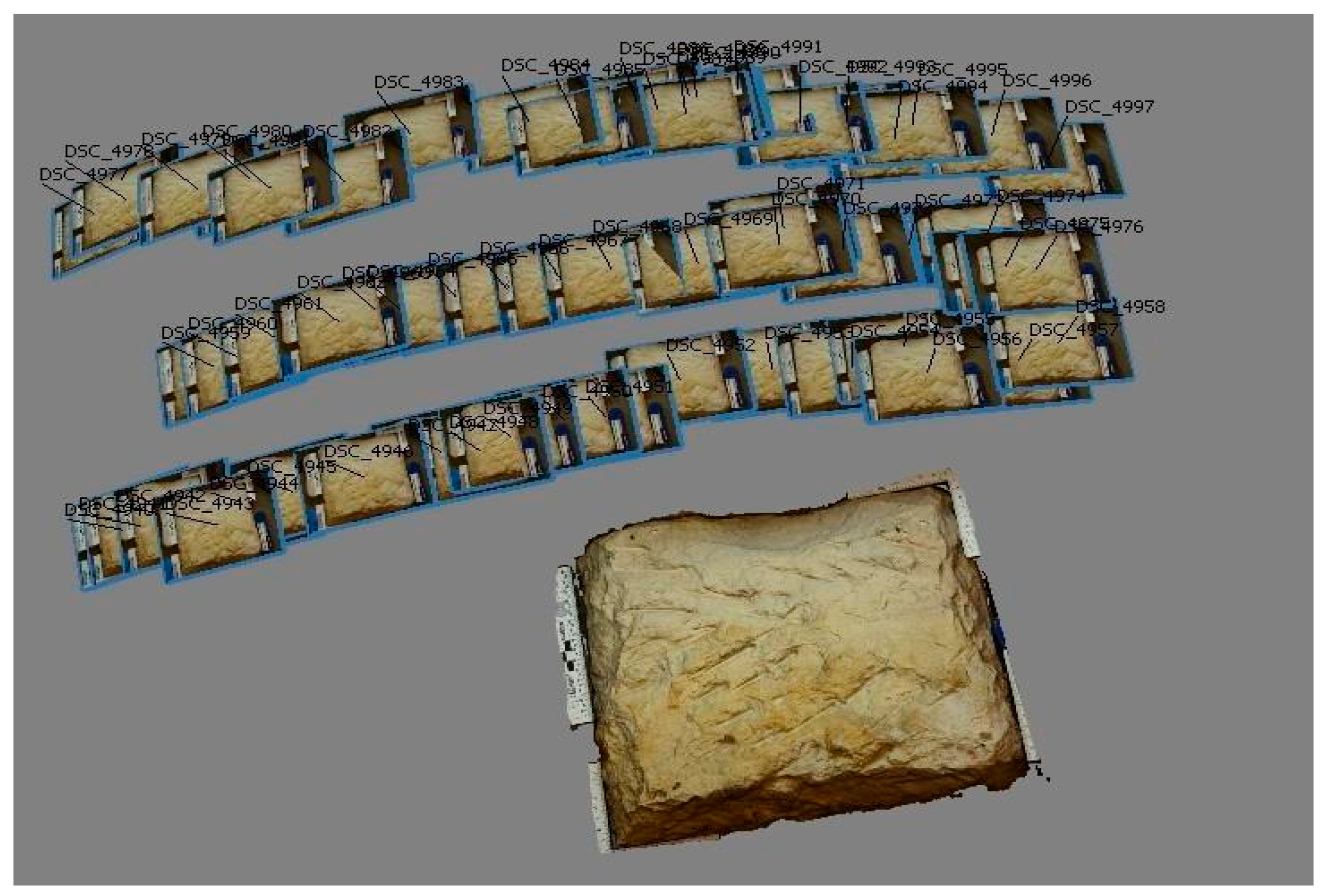
The imaging was carried out using the knowledge gained from previous testing, which focused on the number and configuration of images, choice of lighting and camera settings [32]. For each sample, a set of 50–70 images configured in rows were taken (Figure 1).
Before the final imaging, a set of ground-based identical points had to be set in order to compare stages in the future. For this purpose, different types of identical points were marked on the samples (Figure 2).
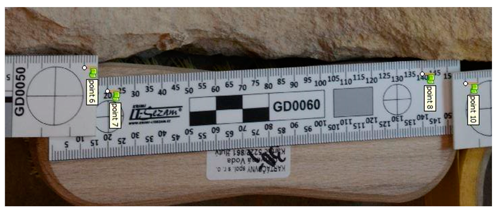
The accuracy of the generated 3D data had to be analysed in detail. The accuracy is directly related to the ground control points used (for setting the dimension and orientation of the 3D output). Dimensional scales were used mainly regarding implementation simplicity. Forensic plastic scales “LT Sezam” of various types were used. These gauges are supplied with a calibration certificate declaring their dimensional accuracy (in the order of 0.05–0.1 mm with respect to the length of the section). An example of a sample image with the gauges is shown in Figure 3.
Photogrammetry image processing for all samples and stages was carried out using standard technological procedures. The Metashape software system (Agisoft) was used.
In order to eliminate systematic errors, all processing was carried out by one worker, with great emphasis on a standardised procedure. Within the individual stages of the photogrammetric processing, the calculation parameters determined by detailed testing in the preparatory phase of the project were adjusted. This included parameters such as model orientation and point cloud formation. The progress of processing all photogrammetric projects was documented by protocols.
Figure 4 shows one of the photogrammetric protocols documenting the number and sizes of lengths used on scales and the choice of points within the scales. Table 1 shows achieved accuracy.
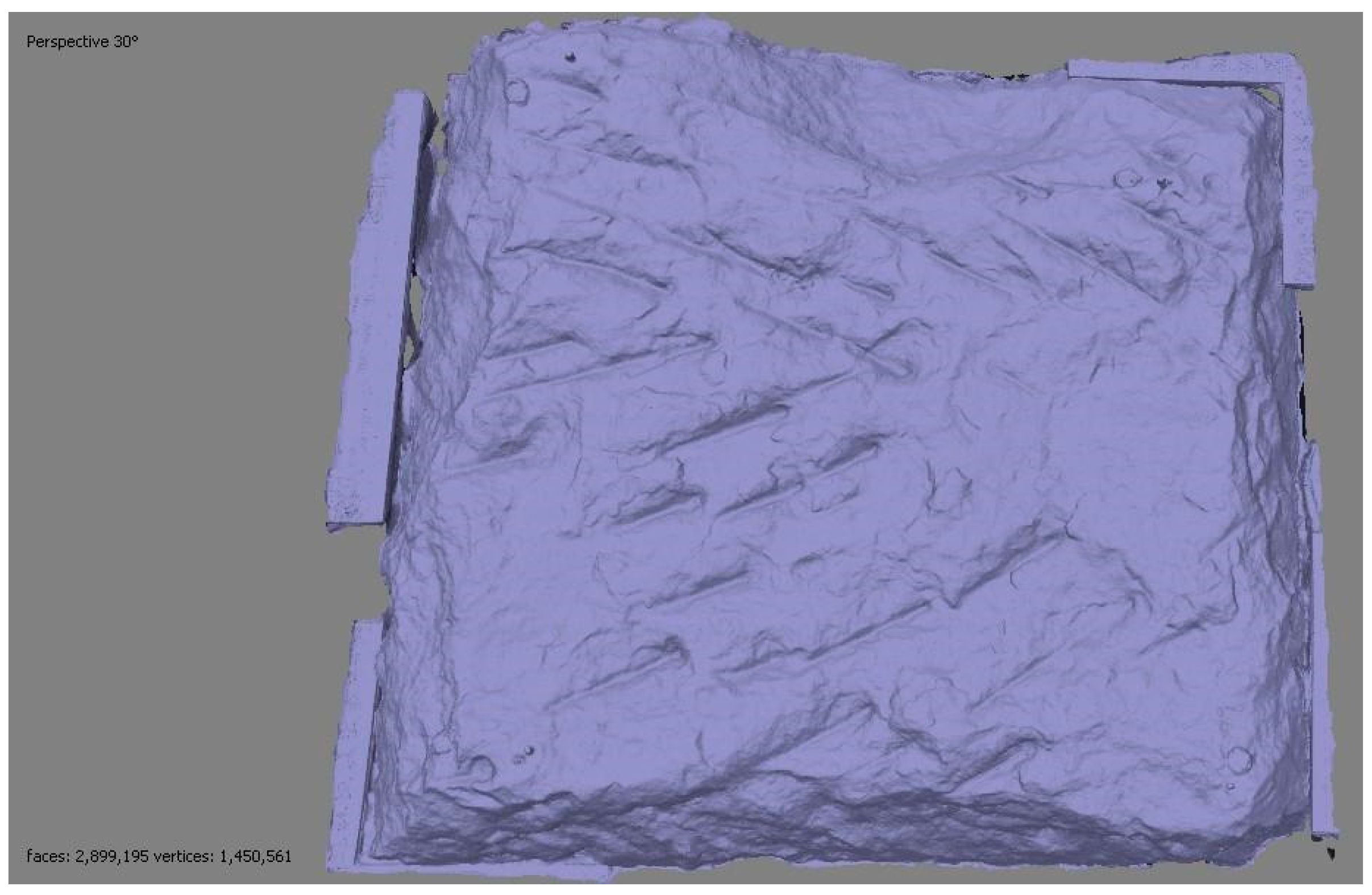
In photogrammetric image processing, geometric accuracy of the 3D outputs was achieved within the 0.05–0.2 mm range using scales, see Figure 4. Further refinement would require specialised tools and equipment. The main 3D output of all photogrammetric projects was a point cloud. The number of “cleaned” points in a cloud ranged from 13 to 25 million points, depending on the sample size, see below. Based on the cloud, a polygonal model (mesh) was created in an untextured (Figure 5) and textured version.
The final step of PGM processing of the 3D data was the reference and registration of the data sets from the two stages. For this purpose, the previously mentioned identical points that were not affected by the restoration intervention were used. These points were used to calculate a transformation key to assign one file to the other, see Figure 6. The reference file was the pre-intervention data.
The specialised free software named XYZTtrans was used to calculate the matching transformation key. The open-source software CloudCompare was used for the actual transformation and for the subsequent analysis of the results. Through testing in the preliminary phase of the project, it was found that the type of identical point does not directly affect the accuracy. The geometric accuracy of the assignment, given by the precision resulting from the calculation of the transformation key, was approximately 0.15 mm for each sample.
For the final analysis of the 3D data, the CloudCompare software was selected.
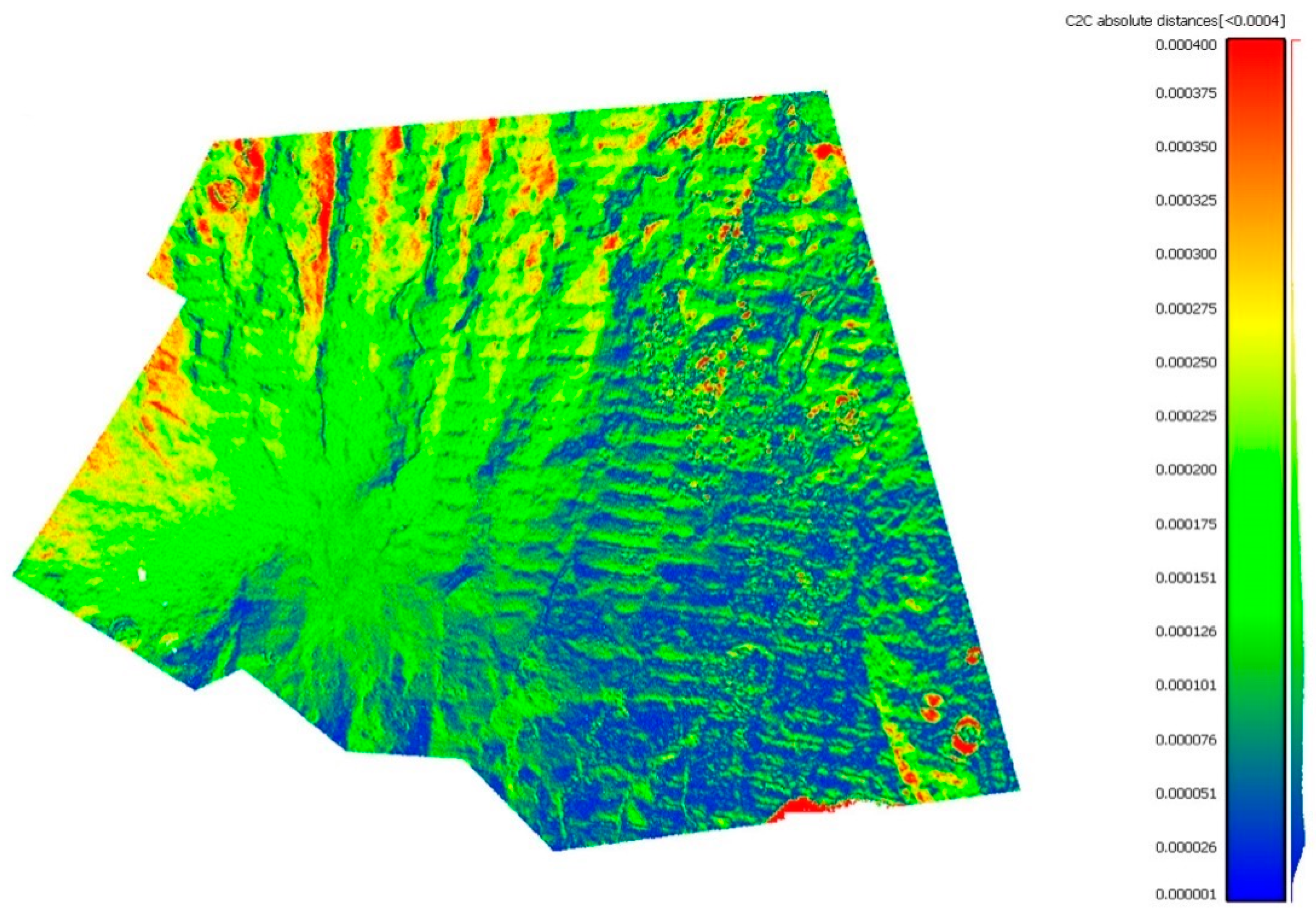
The selection of the software tool was based on the previously performed exhaustive testing [33], and additional experiments in the preparatory phase performed by the authors. The predictive power of the visual result interpretation from the planar 3D point cloud comparison was assessed (Figure 7). The visual interpretation of polygon models from 2D cloud comparisons in the form of vertical sections through suitably chosen planes was also tested. In the end, the use of cross-sections proved to be the most conclusive (in the context of the set of all samples) and the most appropriate for further purposes, see below.
4. Results
4.1. Stone Artefact No. 1
The first stone artefact is a 32 cm × 20 cm “opuka” fragment from the building No. 499/7 in Havelská Street in Prague. The examined surface was finely realigned with an axe with flat teeth. The stone working method indicates a 14th-century period of execution.
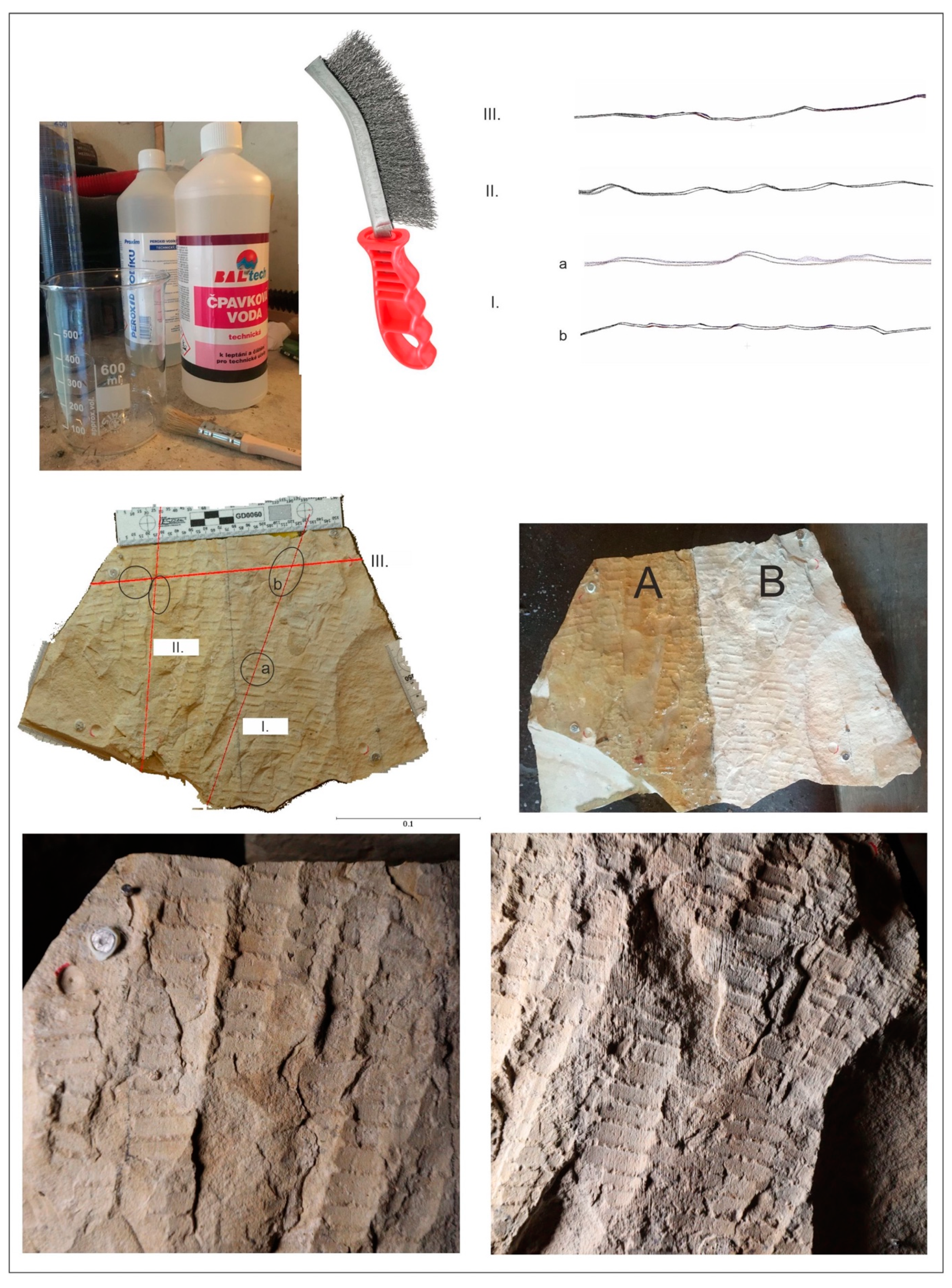
Two restoration interventions were applied to the surface. The surface was divided into areas A and B, where area A was cleaned with so-called ‘ammoniac water’, in the ratio of 1 part ammonia, two parts hydrogen peroxide and three parts distilled water. The solution was applied to the surface with a 2 cm wide nylon fine brush and left for one hour. The application was performed with even brush strokes along the axis of the toothed blade traces. The surface was subsequently washed with distilled water and the process was repeated three more times.
The second area, labelled B, was cleaned mechanically with a steel brush (Figure 8). The steel wires were corrugated with a size of 265 cm × 25 mm. The thickness of the wire was 0.3 mm. The treatment with this brush was again applied in a uniform direction, in this case perpendicular to the axis of the preserved tooth traces of the stonemason’s axe. Cleaning was carried out in strips 2.5 cm wide with approximately 10 brush strokes.
Detailed photogrammetric documentation of sample surfaces yielded the following parameters: the accuracy of the first model calculation (determined using the excess number of lengths on the scales) ‘before intervention’ was 0.085 mm (the number of lengths used was set to eight) and the second model ‘after restoration intervention’ was 0.07 mm (the number of lengths used was set to six). The numbers of cloud points calculated for this sample were 17.1 million (before) and 15.2 million (after). The ground-based quality of both clouds resulting from the transformation key calculation was 0.14 mm (the number of identical points was set to seven).
In the first case, i.e., the application of ammoniac water, when comparing the resulting superimposed sections, it is obvious that Sections II and III at the locations of area A show a correlation of the line course. This fact indicates that there has been almost no loss of material. This treatment was very gentle in this case, both on the surface itself and on the stonemason’s tool traces.
The second method, applied to parts of surface B with a steel brush, already showed changes that were not apparent at first sight. Section Ia,b (Figure 8) show the material changes. There is a loss of material, and, on close inspection of the surface, there is also a deformation of the working traces. The steel bristle grooves show through, which ultimately changes the overall character of the traces, as can be seen in the detail image from area ‘B’.
4.2. Stone Artefact No. 2
The second stone artefact is a 32 cm × 24 cm fragment of brick from building No. 553 in Celetná Street, from the house of the Sixtus family in Prague. The examined surface has been finished with strong blows from a hand-held narrow chisel and a mallet. The method of working suggests a period in the 17th–18th centuries.
Two restoration interventions were applied to the surface. The surface was divided into areas A and B, where area A was cleaned using the “Art Peel” treatment and area B was cleaned with a soft nylon brush (Figure 9). Art Peel is a cleaning system created for cleaning stone, fresco and mortar surfaces. It is a paste system that removes dust, soot, nicotine deposits, etc. from surfaces. Art Peel consists of two components where the first Peel-Base and the second Peel-Active were mixed in a 100:50 ratio. By mixing these two ingredients, a paste is created and applied to the stone surface. Art Peel maturates depending on the application thickness and atmospheric conditions. After maturation, the “film” formed is peeled off, taking care to peel it off gently to avoid secondary damage to the treated surface.
Using the second method, surface B was gently cleaned with a nylon brush and distilled water. The intervention was carried out by gradually wetting and rubbing the surface with a nylon brush in one direction, i.e., the longitudinal direction of the traces from the stone surface outwards. This treatment was applied three times in succession so that all the dirt could be carefully brushed out and washed away. Using this method, as indicated by Section I (Figure 9), caused a material change on the surface and its material. The Art Peel method was gentler on the surface in this case, but minor deformation of the traces did occur. However, this was a negligible loss of 0.02 mm between the two surfaces.
Detailed photogrammetric documentation of sample surfaces yielded the following parameters: the accuracy of the first model’s ‘before intervention’ calculation was 0.2 mm (the number of lengths used was set to eight) and the second model ‘after restoration intervention’ was 0.06 mm (the number of lengths used was set to six). The numbers of cloud points calculated for this sample were 21.2 million (before) and 19.6 million (after). The ground-based quality of both clouds resulting from the transformation key calculation was 0.15 mm (the number of identical points was set to six).
4.3. Stone Artefact No. 3
The stone artefact No. 3 is a 31 cm × 31 cm brick tile from the building No. 499/7 in Havelská Street in Prague. It is probably part of a Baroque pavement from the 18th century. The stone is crafted by hand. The grooves are distinctive.
A double restoration intervention was applied to the surface of the examined stone sample. The surface was divided into areas A and B. The area A was cleaned with the “Art Peel” method and the area B was cleaned with a soft nylon brush (Figure 10). The Art Peel consists of two components, where the first Peel-Base and the second Peel-Active were mixed in a different ratio from that of artefact 1, i.e., in a ratio of 100:10. By mixing these two ingredients, a paste is created and applied to the surface of the stone. After maturation, the “film” formed is peeled off, taking care to peel it off gently to avoid secondary damage to the treated surface. The maturation is recommended for a period of 24 h.
In the second restoration procedure, surface B was gently cleaned with a nylon brush and distilled water.
This method caused a material change on the surface and its loss, as indicated by Section I (Figure 10). The Art Peel method in the ratio of 100:10 was even more gentle on the surface than in the previous case (artefact 2). However, it should be noted that it was not tested on the same rock sample, therefore, if the ratio of both components had been chosen regarding trace preservation, it would have been necessary to test both variants on the same sample.
Detailed photogrammetric documentation of sample surfaces yielded the following parameters. The accuracy of the calculation of the first model ‘before intervention’ was 0.09 mm (the number of lengths used was set to seven) and the second model ‘after restoration intervention’ was 0.06 mm (the number of lengths used was set to six). The number of cloud points calculated for this sample was 17.8 million (before) and 24.8 million (after). The ground-based quality of both clouds resulting from the transformation key calculation was 0.14 mm (when the number of identical points was five).
4.4. Stone Artefact No. 4
The stone artefact No. 4 is represented by a 28 cm × 15 cm limestone fragment from the object 553 in Celetná Street, in the house U Sixtů in Prague. The examined surface was finely realigned with the blows of a chisel with pointed teeth. The method of work indicates a period in the 18th–19th century. In some places, the surface work was poorly identifiable.
In this case, a chemical cleaning using the Schmutzlöser agent from Remmers was applied to the fragment (Figure 11). Schmutzlöser is a clear solution containing surfactants (ca. 10%). This solution was applied with a brush to the surface of the stone. After its application, the solution was left on the surface for approximately 1 h. Then it was washed off with distilled water and the process was repeated three times. The use of this cleaner for the purpose of limestone cleaning was deliberately chosen in consideration of the rock’s sensitivity to chemicals.
The application of this agent showed very strong cleaning capabilities. The surface, which showed signs of heavy fouling, was completely cleaned. This resulted in a loss of material. However, in some places where small cracks occurred before application; due to the aggressiveness of the product, the surface was disrupted. These small “flakes” fell off after the application of the product, which was also proven by comparing the sections.
Detailed photogrammetric documentation of this specimen’s surfaces showed the following parameters: the accuracy of the calculation of the first ‘before intervention’ model was 0.08 mm (the number of lengths used was set to seven) and the second model ‘after restoration intervention’ was 0.07 mm (the number of lengths used was set to five). The numbers of cloud points calculated for this sample were 12.9 million (before) and 15.8 million (after). The ground-based quality of both clouds resulting from the transformation key calculation was 0.17 mm (when the number of identical points was seven).
4.5. Stone Artefact No. 5
The last stone artefact to be cleaned was a Meissen sandstone, for which a laser was used to clean the surface. This is a block measuring approximately 26 cm × 26 cm, and it was the only one that bore no traces of historical working but was experimentally worked with a 4 cm straight-bladed chisel to experimentally test changes in the surface topography over time. The surface was exposed to the natural outdoor environment for ten years so that degradation processes could be monitored. Although this is a very short period, the surface shows biological attack and partial mechanical contamination. Although a rock artefact with a greater layer of surface contamination would be more suitable for laser cleaning, assessment of the laser application in relation to the change in surface topography using near PMG also provides valuable information on the destructive or non-destructive nature of the method.
Three surfaces were selected for the sample and experimentally cleaned with the laser (Figure 12; note the photo on the top left is for illustrative purposes only). The Palladio/Quanta Systems, Italy, ND-YAG laser with the following technical parameters was used for cleaning: energy/pulse 500 mJ, wavelength 1064 nm, output beam diameter, max 7 mm and max repetition rate 15 Hz.
Detailed photogrammetric documentation of this specimen’s surface showed the following parameters. The accuracy of the calculation of the first ‘before intervention’ model was 0.16 mm (the number of lengths used was set to 8), and the second model ‘after restoration intervention’ was 0.13 mm (the number of lengths used was set to 8). The numbers of cloud points calculated for this sample were 78.1 million (before) and 91.1 million (after). The ground-based quality of both clouds resulting from the transformation key calculation was 0.16 mm (when the number of identical points was three).
By performing an experimental photogrammetric evaluation of the changes in surface topography, it was found that the use of this method does not cause loss of material from the stone surface. As a result, the correlation curve is identical. For Section III, although there is a higher loss of material in two places, it is a marginal amount in the whole, which may be caused by a larger number of deposits before laser treatment.
5. Conclusions
Based on the performed experimental research, it can be concluded that the method of close-range photogrammetry can be used for the purpose of evaluating the “friendliness” of restoration interventions towards historical traces of work. In our case, lasers and so-called ammoniac water were the best and gentlest. Application of these methods did not cause any material change and the traces were not deformed. The application of art peel also ended relatively well, with a slight material change, but with no significant destruction of the traces. Using the soft brush caused a slight material change on the surface, but it is possible to conclude that this method was not very destructive. The application of Schmutzlöser by Remmers affected the stone surface more significantly, resulting in changes in the working traces. The last method of mechanical cleaning with a steel brush was the most destructive of our set of surface cleaning methods. There was the greatest material loss detected as well as deformation of the trace’s shape. Deep grooves were created, and this resulted in a definitive change in the character of the historic traces.
However, the accuracy mentioned above must be taken into consideration when determining the specific value of the material loss. For more detailed analyses, it would certainly be necessary to choose methods and tools specialised or newly designed for that purpose. This would be more time-consuming and more economically demanding. Our aim was to use commonly available technologies, easily applied in-situ and obtain outputs at the “limit of what is possible” (in terms of quality). It is possible to say that this task has been fulfilled in terms of detailed metric documentation of surfaces.
Fine results using common tools were achieved in terms of geometric quality, level of detail and the documentation predictive power. The model’s geometric accuracy is in the single tenths of mm, as well as matching of the two datasets (before and after). It is possible to make an educated guess that their differences can be subtracted from the resulting clouds with an accuracy/resolution of 0.2–0.4 mm. Outputs in the form of cloud sections capture general trends properly (areas where material has been reduced by the intervention).
In conclusion, it should be emphasised that the choice of restoration intervention is always based on the specific situation, and the aim of the presented article is not the selection of a suitable restoration procedure as such, but the verification of the close-range photogrammetry for the purpose of determining the appropriateness of restoration interventions regarding the preservation of historical traces after working. In this perspective, the use of close-range photogrammetry can easily and effectively contribute to the selection of appropriate restoration interventions.
Author Contributions
Conceptualization, K.K. and M.C.; methodology, M.C. and J.H.; experimental investigation M.C., K.K. and E.M.; photogrammetry J.H. and E.F.; data curation, E.M.; writing—review and editing, K.K. and E.M.; project administration, K.K. All authors have read and agreed to the published version of the manuscript.
Funding
This research was funded by the Ministry of Culture of the Czech Republic grant number DG20P02OVV021.
Data Availability Statement
Not applicable.
Acknowledgments
This research was supported by the program of applied research and development of national and cultural identity (NAKI) of the Ministry of Culture of the Czech Republic—grant No. DG20P02OVV021 “Building stone surface topography and its application in the field of stone features restoration”.
Conflicts of Interest
The authors declare no conflict of interest.
References
- Vzorník Stop a Rekonstrukce Historických Kamenických Nástrojů. Available online: https://stonetopography.is.cvut.cz (accessed on 26 November 2022).
- Cihla, M.; Kovářová, K.; Tryml, M.; Bartoš, L.; Semerád, M.; Valach, J.; Panáček, M. Opracování stavebního Kamene románských domů pražské podhradní aglomerace. Staletá Praha 2021, 37, 2–38. [Google Scholar]
- Inetrnational Council on Monuments and Sites. Available online: https://www.icomos.de (accessed on 26 November 2022).
- Daniels, C. The Stone Restoration Handbook: A Practical Guide to the Conservation Repair of Stone and Masonry; The Crowood Press Ltd.: Marlborough, UK, 2015; pp. 177–197. [Google Scholar]
- Maxwell, I. Inform Guide: Cleaning Sandstone-Risks and Consequences; Technical Conservation, Research and Education Group: Edinburgh, UK, 2007; pp. 1–7. [Google Scholar]
- Delegou, E.T.; Avdelidis, N.P.; Karaviti, E.; Maroupoulou, A. NDT&E techniques and SEM-EDS for the assessment of cleaning interventions on Pentelic marble surface. X-ray Spectrom. 2008, 37, 435–443. [Google Scholar] [CrossRef]
- Bláha, J. Historic traceology as a complex tool for rediscovery of lost construction skills and techniques. In Proceedings of the 13th International Conference on Studies, Repairs and Maintenance of Heritage Architecture, New Forest, UK, 25–27 June 2013. [Google Scholar] [CrossRef]
- Eeckman, A. Studying woodworking technology on ancient shipwrecks through digital photography and photogrammetry. In Proceedings of the Maritime Archaeology Graduate Symposium 2019, Southampton, UK, 29–31 March 2019. [Google Scholar] [CrossRef]
- Marshall, M.E.; Johnson, A.A.; Summerskill, S.J.; Baird, Q.; Esteban, E. Automating photogrammetry for the 3D digitisation of small artefact collections. Int. Arch. Photogramm. Remote Sens. Spatial Inf. Sci. 2019, XLII-2/W15, 751–757. [Google Scholar] [CrossRef]
- Dhanda, A. The Geometric Documentation of Painted Surfaces. Master’s Thesis, Carleton University, Ottawa, ON, Canada, September 2019. [Google Scholar]
- Gembinski, C. Digital Field Documentation: The Central Park Obelisk. In Proceedings of the 13th International Congress on the Deterioration and Conservation of Stone 2016, Glasgow, UK, 6–10 September 2016. [Google Scholar]
- Coe, J.A.; Sherwood, S.I.; Messerich, J.A.; Pillmore, C.L.; Andersen, A.; Mossotti, V.G. Measuring stone decay with close range photogrammetry. In Proceedings of the 7th International Congress on Deterioration and Conservation of Stone, Lisbon, Portugal, 15–18 June 1992. [Google Scholar]
- Inkpen, R.J.; Collier, P.; Fontana, D. Close-range photogrammetric analysis of rock surfaces. the 3D digitisation of small artefact collections. Z. Geomorphol. Suppl. 2000, 120, 67–81. [Google Scholar]
- Ressl, C. Reconstruction of the Pegasus statue on top of the State Opera House in Vienna using photogrammetry and terrestrial and close-range laser scanning. In Proceedings of the Conference in Lasers in the Conservation of Artworks: LACONA VI, Vienna, Austria, 21–25 September 2005. [Google Scholar] [CrossRef]
- Bartoš, K.; Pukanská, K.; Repáň, P.; Kseňak, Ľ.; Sabová, J. Modelling the Surface of Racing Vessel’s Hull by Laser Scanning and Digital Photogrammetry. Remote Sens. 2019, 11, 1526. [Google Scholar] [CrossRef]
- Kadobayashi, R.; Kochi, N.; Otani, H.; Furukawa, R. Comparison and evaluation of laser scanning and photogrammetry and their combined use for digital recording of cultural heritage. Int. Arch. Photogramm. Remote Sens. Spat. Inf. Sci. 2004, 35, 6. [Google Scholar]
- Pavelka, K.; Řezníček, J.; Bílá, Z.; Prunarová, L. Non Expensive 3D Documentation and Modelling of Historical Object and Archaeological Artefacts by Using Close Range Photogrammetry. Geoinformatics 2013, 10, 53–66. [Google Scholar] [CrossRef]
- Pavelka, K.; Řezníček, J. New Low-cost Automated Processing of Digital Photos for Documentation and Visualisation of the Cultural Heritage. Geoinformatics 2011, 6, 245–258. [Google Scholar] [CrossRef]
- Chaloupka, J.; Růžička, P. Nálezy geometrických graffiti na omítkách zámku v Sokolově. Průzkumy památek 2019, 26, 110–126. [Google Scholar]
- Abate, D.; Trentin, M. Hidden graffiti identification on marble surfaces through photogrammetry and remote sensing techniques. Int. Arch. Photogramm. Remote Sens. Spatial Inf. Sci. 2019, XLII-2/W15, 1–8. [Google Scholar] [CrossRef]
- Anghelutā, L.M.; Rādvan, R. Macro photogrammetry for the damage assessment of artwork painted surfaces. Int. Arch. Photogramm. Remote Sens. Spatial Inf. Sci. 2019, XLII-2/W15, 101–107. [Google Scholar] [CrossRef] [Green Version]
- Weigert, A. Applied Craft Science in Traditional Timber Framing Conservation. Master’s Thesis, Carleton University, Ottawa, ON, Canada, June 2021. [Google Scholar]
- Kozub, B.; Kozub, P. 3D Photo Monitoring as a Long-term Monument Mapping Method for Stone Sculptures. In Proceedings of the 13th International Congress on the Deterioration and Conservation of Stone, Glasgow, UK, 6–10 September 2016. [Google Scholar]
- Torresani, A.; Remondino, F. Videogrammetry vs. photogrammetry for heritage 3D reconstruction. Int. Arch. Photogramm. Remote Sens. Spatial Inf. Sci. 2019, XLII-2/W15, 1157–1162. [Google Scholar] [CrossRef]
- Brcek, M.; Fraštia, M.; Ondrášik, M.; Kopecký, M. Determination of deformation characteristics of natural rock using methods of close-range photogrammetry. IOP Conf. Ser. Mater. Sci. Eng. 2020, 960, 022067. [Google Scholar] [CrossRef]
- Pavelka, K.; Pavelka, K.; Matoušková, E.; Smolík, T. Earthen Jewish Architecture of Southern Morocco: Documentation of Unfired Brick Synagogues and Mellahs in the Drâa-Tafilalet Region. Appl. Sci. 2021, 11, 1712. [Google Scholar] [CrossRef]
- Hayes, J.; Fai, S.; Kretz, S.; Ouimet, C.; White, P. Digitally-Assisted Stone Carving of a Relief Sculpture for the Parliament Buildings National Historic Site of Canada. ISPRS Ann. Photogramm. Remote Sens. Spat. Inf. Sci. 2019, II-5/W3, 97–103. [Google Scholar] [CrossRef]
- Janvier, R.; Brunetaud, X.; Beck, K.; Janvier-Badosa, S.; Al-Mukhtar, M. The Potential of Laser Scanning to Describe Stone degradation. In Proceedings of the 13th International Congress on the Deterioration and Conservation of Stone, Glasgow, UK, 6–10 September 2016. [Google Scholar]
- McGibbon, S.; Abdel-Wahab, M. Emerging Digitisation Trends in Stonemasonry Practice. In Proceedings of the 13th International Congress on the Deterioration and Conservation of Stone, Glasgow, UK, 6–10 September 2016. [Google Scholar]
- Štroner, M.; Urban, R.; Křemen, T.; Koska, B. Accurate Measurement of the Riverbed Model for Deformation Analysis using Laser Scanning Technology. Geoinformatics 2018, 17, 81–92. [Google Scholar] [CrossRef]
- Lehr, R. Pläner: A traditional building stone in Saxo-Bohemian Cretaceous and Münsterland Cretaceous Basin. Environ. Earth Sci. 2022, 7, 219. [Google Scholar] [CrossRef]
- Zemánková, A. Detail metrical documentation of stone block surfaces. Master’s Thesis, Czech Technical University in Prague, Prague, Czech Republic, June 2019. (In Czech). [Google Scholar]
- Němec, D. Detailed documentation and analysis of traces of stone block surfaces treatment. Master’s Thesis, Czech Technical University in Prague, Prague, Czech Republic, May 2020. (In Czech). [Google Scholar]
Figure 1.
Preview of the image configuration for one of the samples.

Figure 2.
Preview of the types of ground-based identical points used—(a) nail; (b) chop mark; (c) glued mark; (d) drilled mark.
Figure 2.
Preview of the types of ground-based identical points used—(a) nail; (b) chop mark; (c) glued mark; (d) drilled mark.

Figure 3.
Photograph of the “Stone 3” sample with scales (stage after restoration intervention).

Figure 4.
This is a figure. Schemes follow the same formatting.

Figure 5.
Example of one of the photogrammetric processing outputs—a sample 3D polygon model without texture.
Figure 5.
Example of one of the photogrammetric processing outputs—a sample 3D polygon model without texture.

Figure 6.
Example of data collection in CloudCompare software to calculate a transformation key.

Figure 7.
Example output—point clouds area comparison, dips.

Figure 8.
“Opuka” fragment treated with ammoniac water (A) and steel brush (B) (centre right), with an indication of sections used to evaluate changes after restoration interventions (centre left), surface detail cleaned with ammoniac water (bottom left) and surface detail with clear grooves after using a metal brush (bottom right).

Figure 9.
“Opuka” fragment treated with Art Peel (100:50) (A) and soft nylon brush (B) (top left) with indication of section used to evaluate changes after restoration interventions (bottom left), surface detail cleaned with Art Peel (right).
Figure 9.
“Opuka” fragment treated with Art Peel (100:50) (A) and soft nylon brush (B) (top left) with indication of section used to evaluate changes after restoration interventions (bottom left), surface detail cleaned with Art Peel (right).

Figure 10.
The “opuka” tile treated with Art Peel (100:10) (A) and a soft nylon brush with distilled water (B), showing the section used to evaluate changes after restoration interventions (centre left), surface detail cleaned with art peel (centre right) and surface detail cleaned with a nylon brush and distilled water (right).

Figure 11.
Limestone fragment treated with Schmutzlöser by Remmers, with a section marked to evaluate the changes after restoration interventions.
Figure 11.
Limestone fragment treated with Schmutzlöser by Remmers, with a section marked to evaluate the changes after restoration interventions.

Figure 12.
Sandstone fragment after laser treatment with sections used to evaluate changes after restoration interventions.
Figure 12.
Sandstone fragment after laser treatment with sections used to evaluate changes after restoration interventions.


Table 1.
Achieved errors—example—part of the FTG protocol.
| Label | Distance (mm) | Error (mm) |
|---|---|---|
| point 1_point 2 | 70.09 | 0.94 |
| Point 3_point 4 | 70.01 | 0.14 |
| Point 7_point 8 | 69.97 | −0.34 |
| Point 9_point 10 | 139.93 | −0.67 |
| Point 11_point 12 | 119.95 | −0.50 |
| Point 5_point 6 | 90.04 | 0.45 |
| Total | 0.57 |
Disclaimer/Publisher’s Note: The statements, opinions and data contained in all publications are solely those of the individual author(s) and contributor(s) and not of MDPI and/or the editor(s). MDPI and/or the editor(s) disclaim responsibility for any injury to people or property resulting from any ideas, methods, instructions or products referred to in the content. |
© 2023 by the authors. Licensee MDPI, Basel, Switzerland. This article is an open access article distributed under the terms and conditions of the Creative Commons Attribution (CC BY) license (https://creativecommons.org/licenses/by/4.0/).
Share and Cite
MDPI and ACS Style
Hodač, J.; Kovářová, K.; Cihla, M.; Matoušková, E.; Frommeltová, E. Photogrammetric Documentation of Stone Surface Topography Changes as a Tool in Conservation Praxis. Buildings 2023, 13, 439. https://doi.org/10.3390/buildings13020439
AMA Style
Hodač J, Kovářová K, Cihla M, Matoušková E, Frommeltová E. Photogrammetric Documentation of Stone Surface Topography Changes as a Tool in Conservation Praxis. Buildings. 2023; 13(2):439. https://doi.org/10.3390/buildings13020439
Chicago/Turabian StyleHodač, Jindřich, Kateřina Kovářová, Michal Cihla, Eva Matoušková, and Eva Frommeltová. 2023. "Photogrammetric Documentation of Stone Surface Topography Changes as a Tool in Conservation Praxis" Buildings 13, no. 2: 439. https://doi.org/10.3390/buildings13020439
Note that from the first issue of 2016, this journal uses article numbers instead of page numbers. See further details here.