Biological Applications of Short Wavelength Microscopy Based on Compact, Laser-Produced Gas-Puff Plasma Source

 ,
,  and
and 
Abstract
:Featured Application
Abstract
1. Introduction
2. Materials and Methods—Double Stream Gas-Puff Target Source Description
2.1. Pressure Optimization
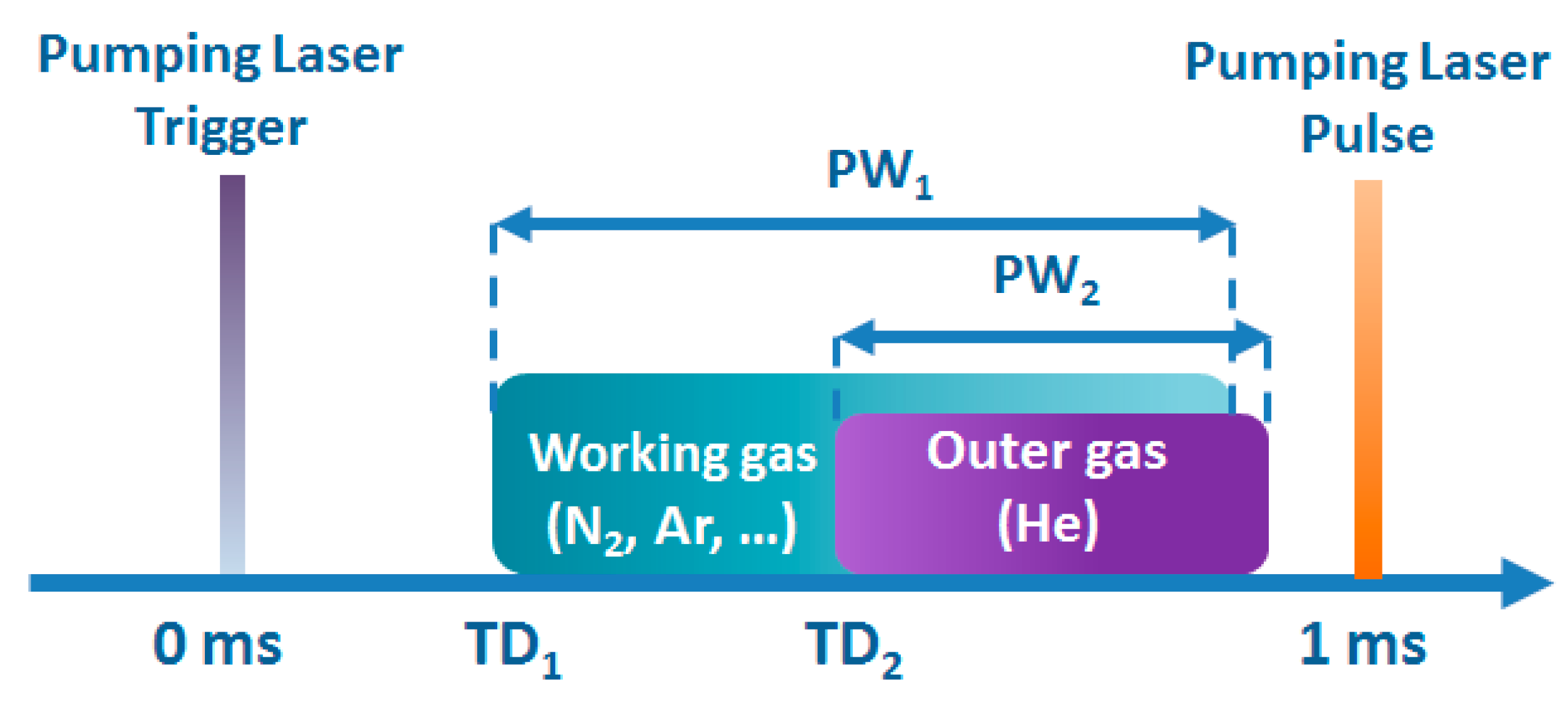
2.2. Time Synchronization
3. EUV and SXR Full Field Microscopes Based on a Double Stream Gas-Puff Target Source
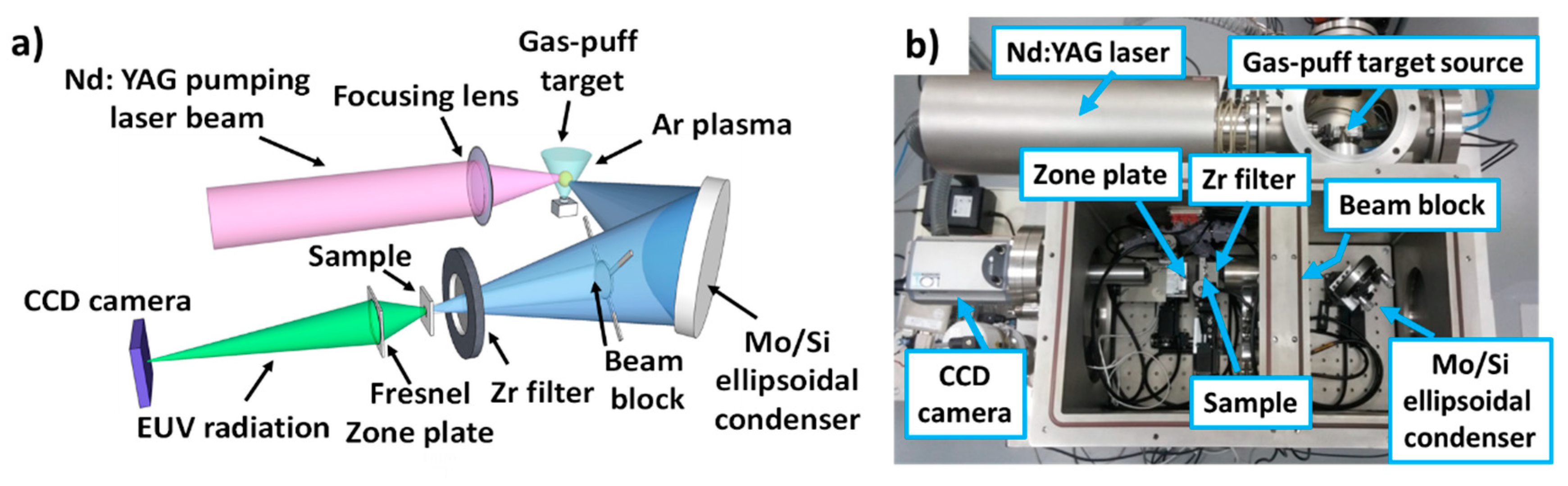
3.1. Full Field EUV Microscope
3.1.1. EUV Source Spectral Distribution and Photon Flux Estimation
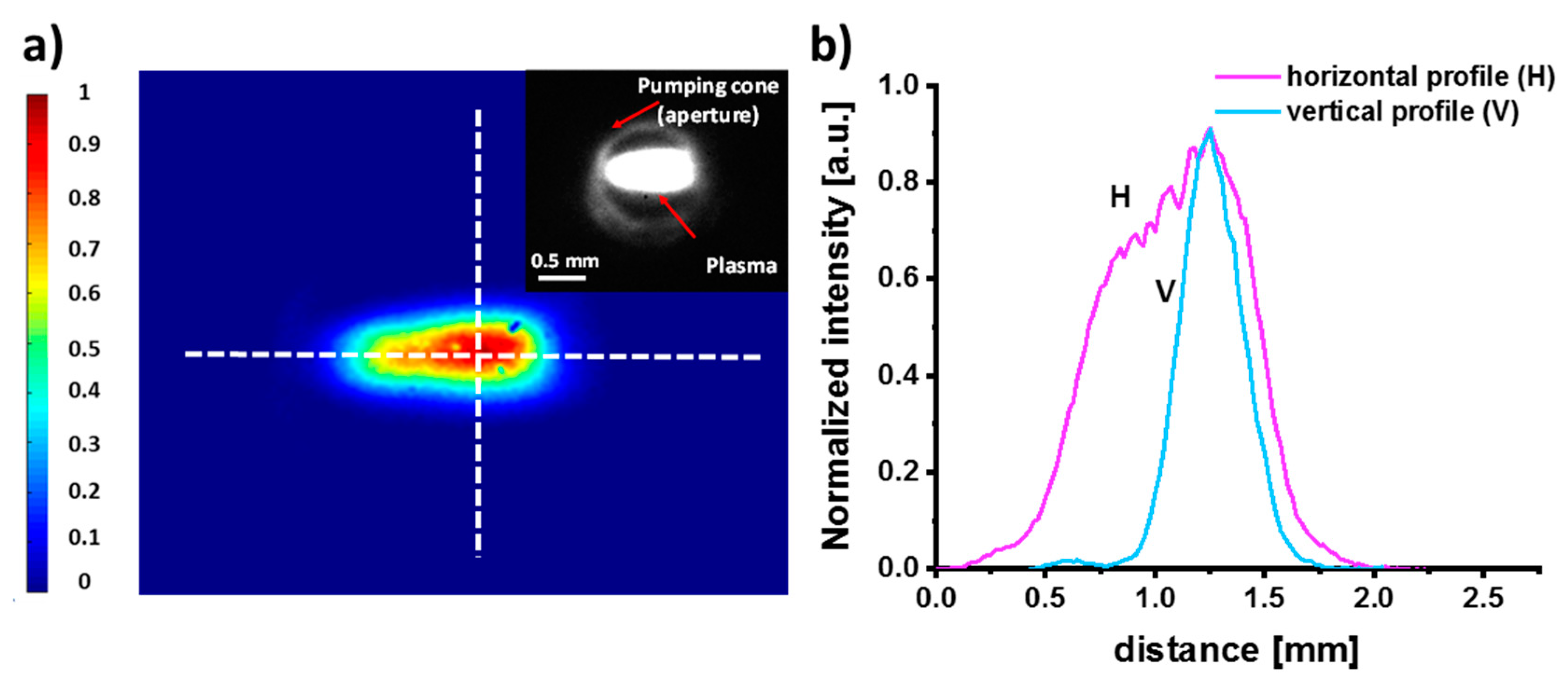
3.1.2. EUV Source Plasma Size Estimation
3.1.3. Fresnel Zone Plate for EUV Microscopy
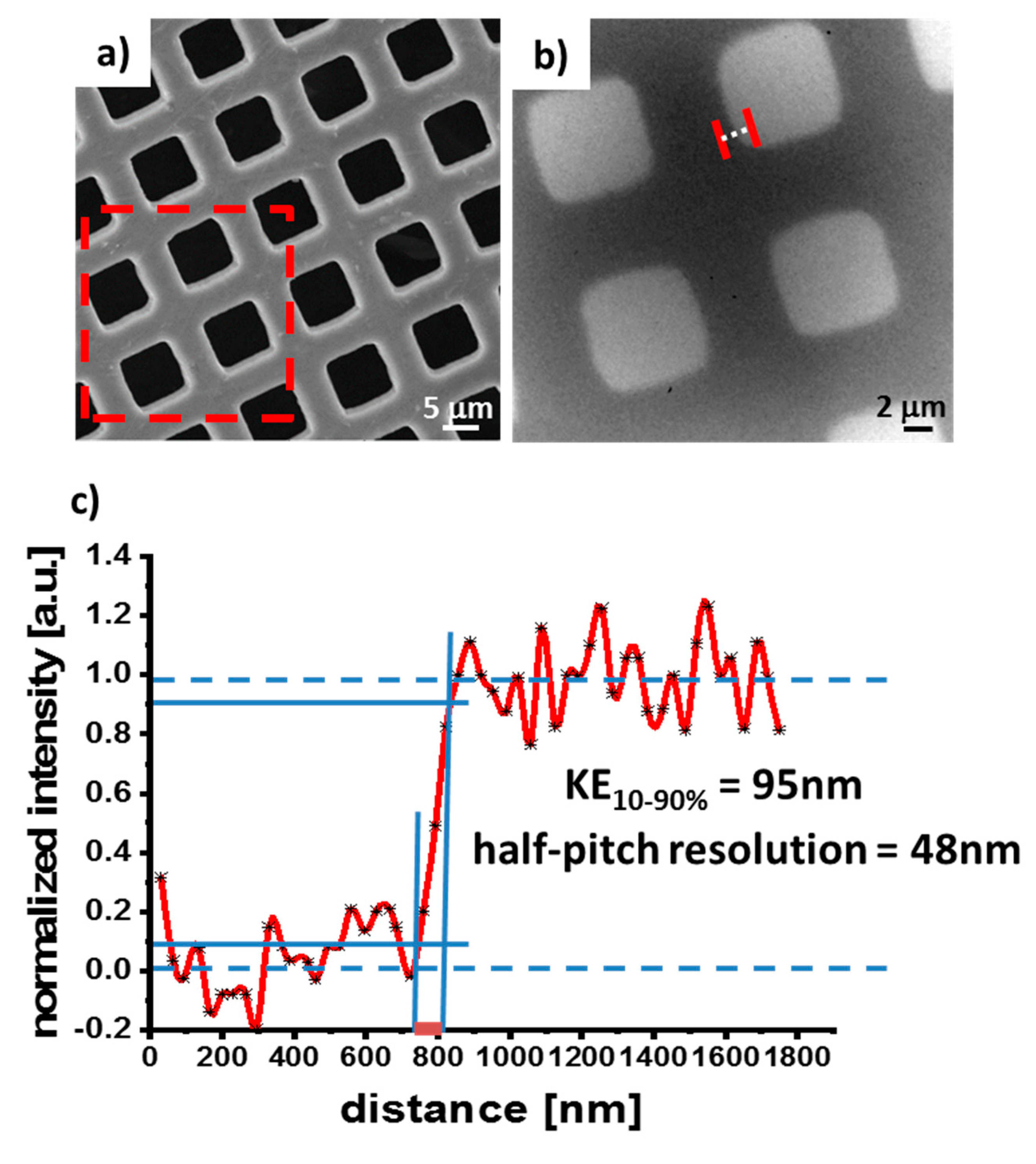
3.1.4. EUV Full Field Imaging of Test Objects and Spatial Resolution Estimation
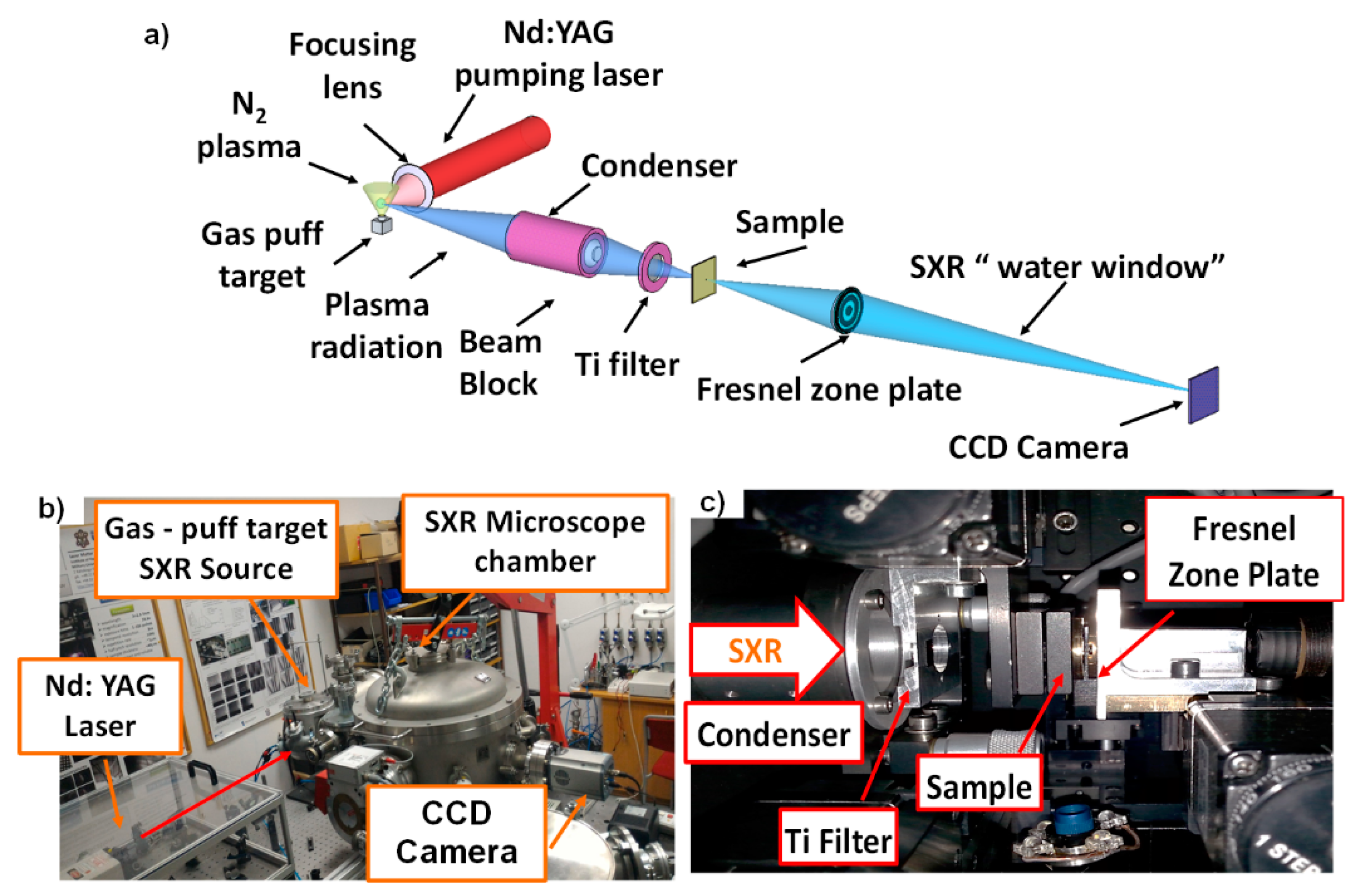
3.2. Full Field SXR Microscope
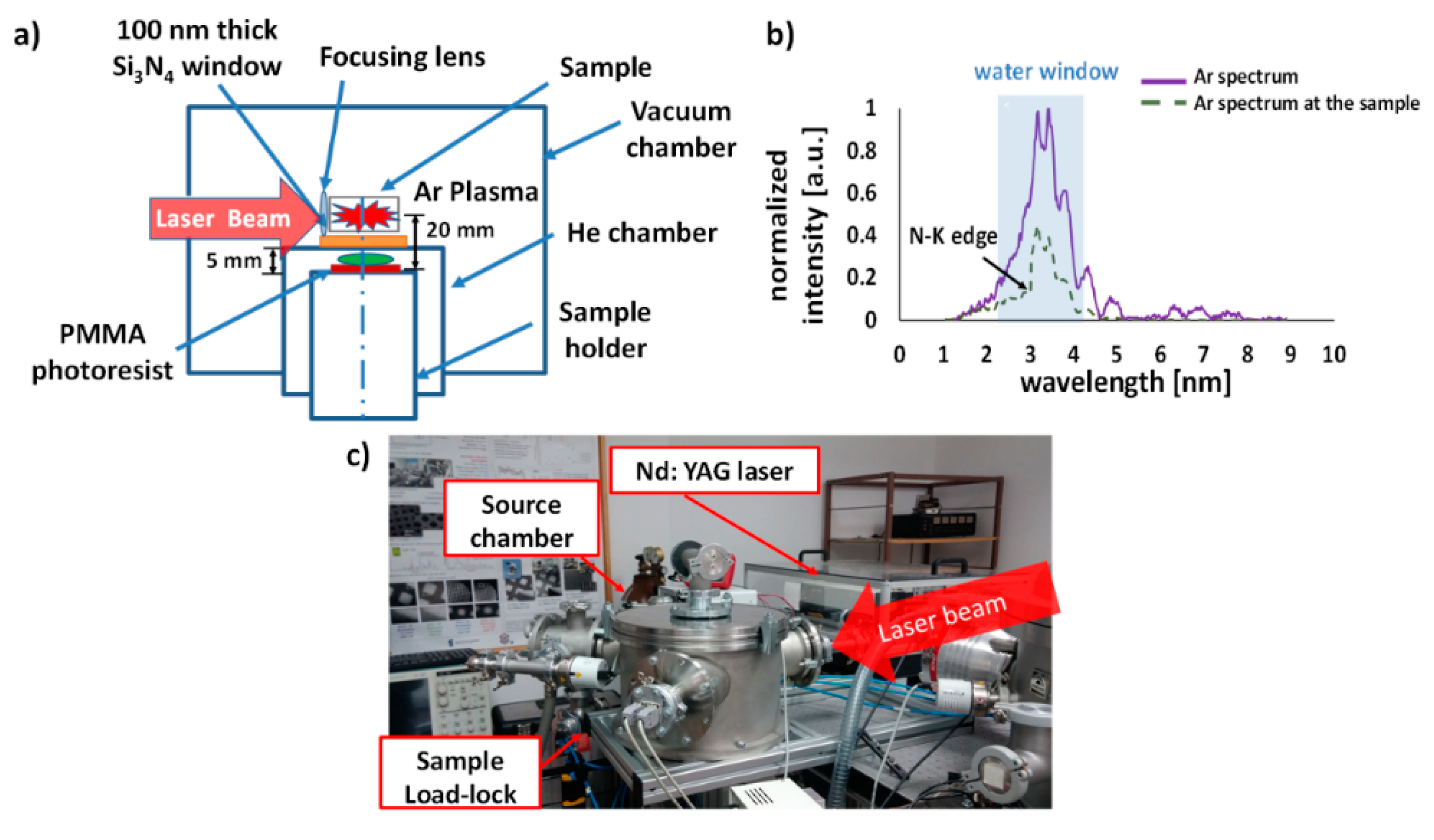
3.2.1. SXR Source Spectral Distribution and Photon Flux Estimation
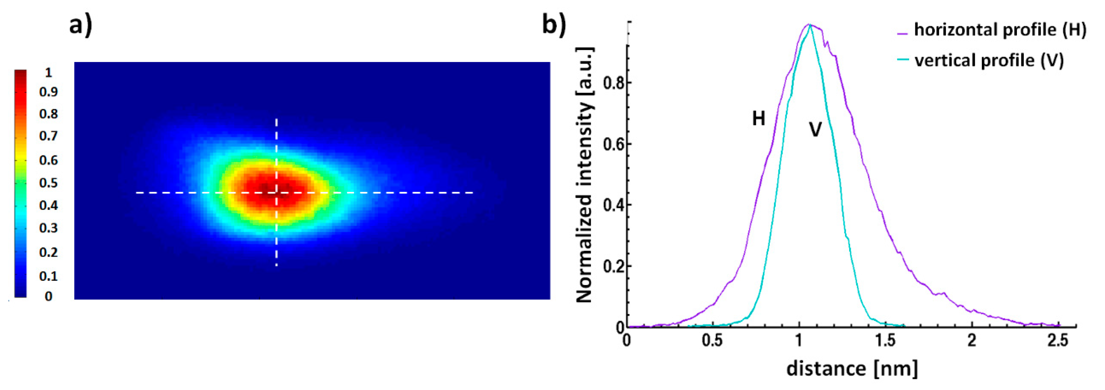
3.2.2. SXR Source Plasma Size Estimation
3.2.3. Fresnel Zone Plate for SXR Microscopy
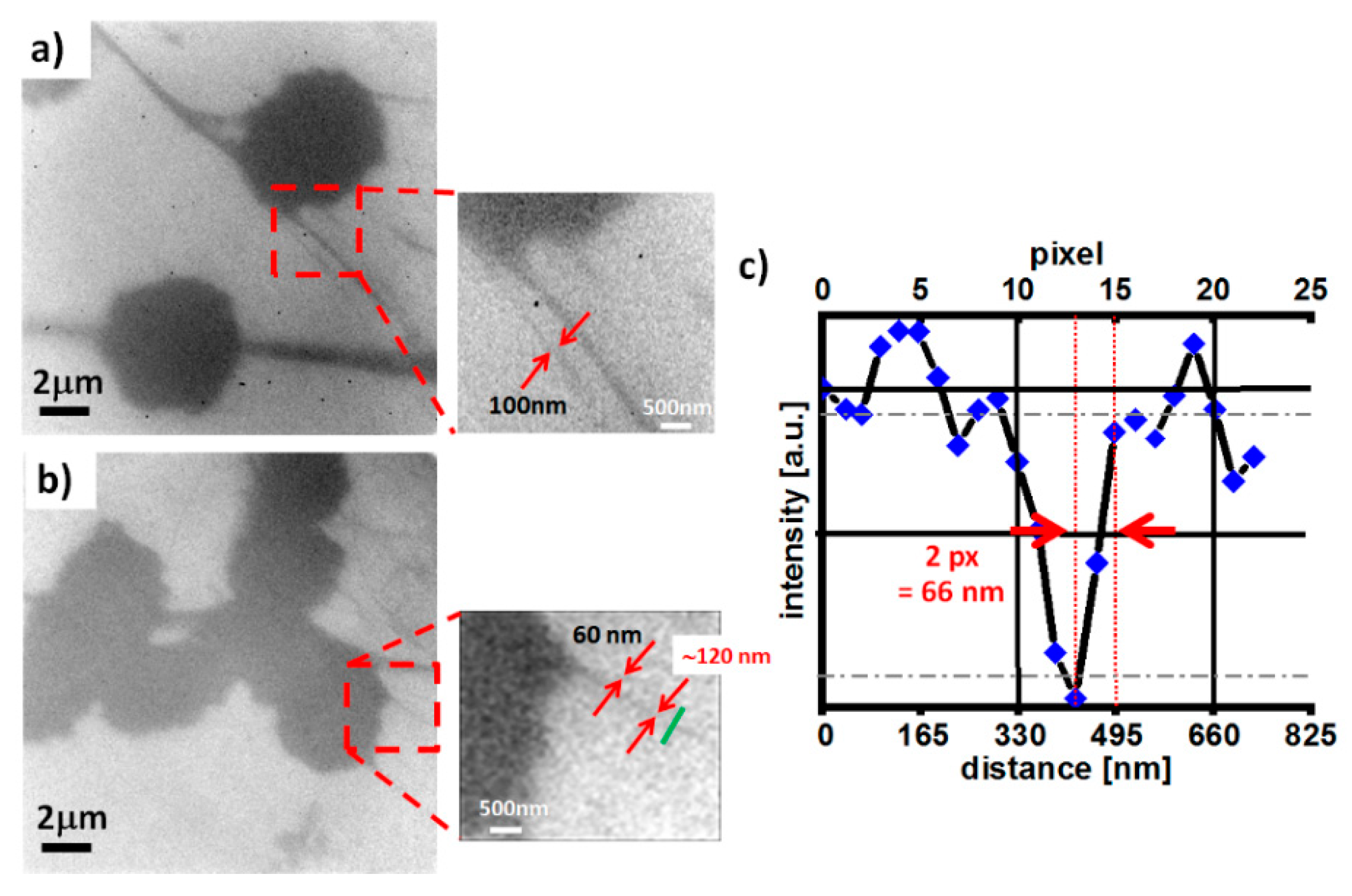
3.2.4. SXR Full Field Imaging of Test Objects and Spatial Resolution Estimation
3.3. SXR Tomography and 3D Imaging
3.4. SXR Contact Microscope
4. Biological Applications of EUV/SXR Microscopes Based on a Double Stream Gas-Puff Target Source
4.1. A 2D Full Field Imaging of Biological Samples
4.1.1. EUV Bioimaging
CT 26 Fibroblast Cells from Mus musculus Colon Carcinoma
Diatoms
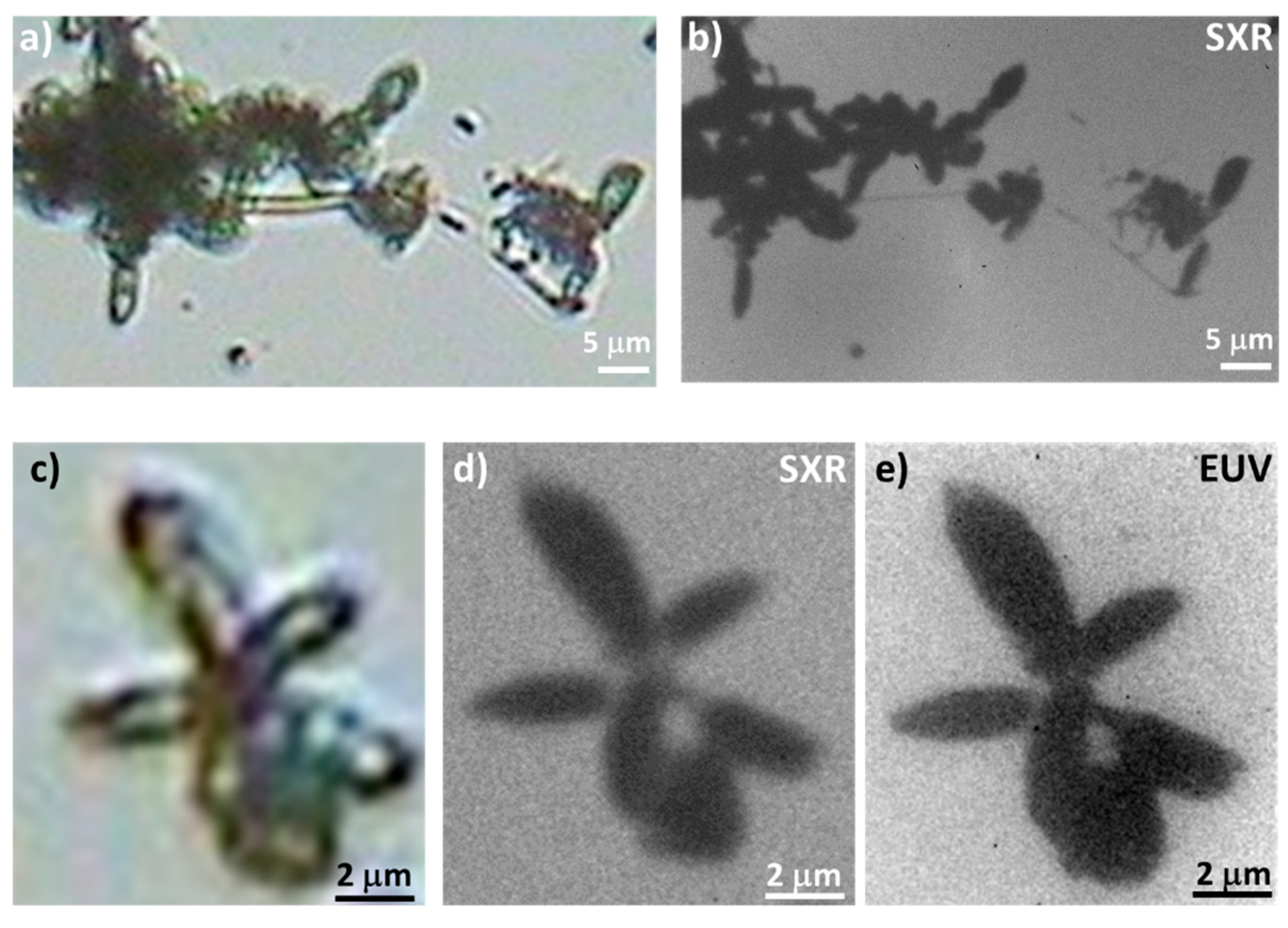
Chrysodidymus synuroideus Algae
4.1.2. SXR Bioimaging
DNA Plasmids pBR322
CT 26 Fibroblasts Cells from Mus Musculus Colon Carcinoma
Diatoms
Chrysodidymus synuroideus Algae
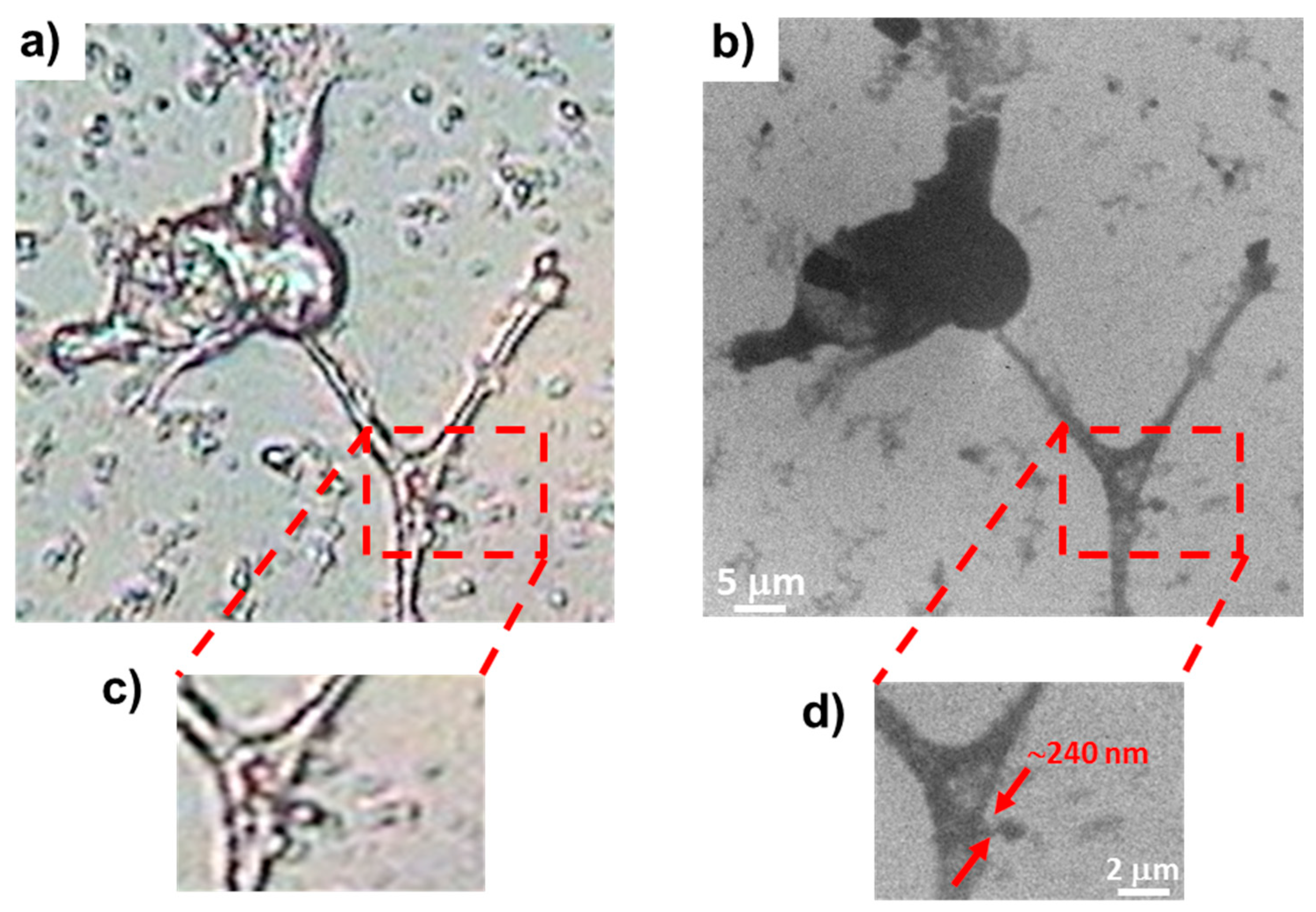
Hippocampal Neurons from E17 Mouse Embryos
4.2. Angular Projection SXR Tomography for Biological Nanoimaging
4.2.1. Hep-2 Cells Crystals
4.2.2. Caffeine Fibers
4.3. Imaging of Dried and Fixed Biological Samples Using Contact Microscopy
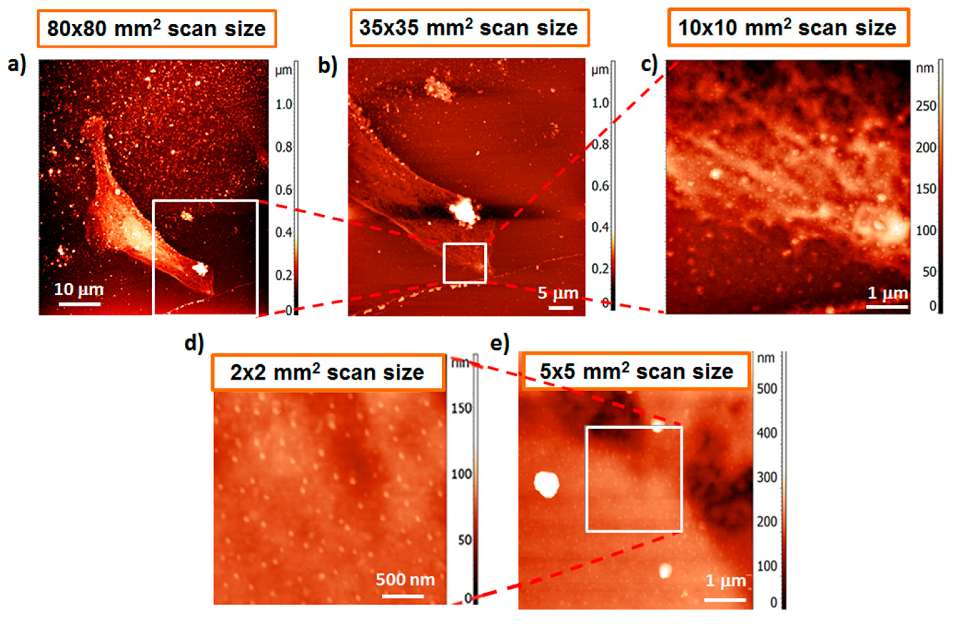
4.3.1. Non-Malignant Human Bladder HCV29 Cells
4.3.2. T24 Cancer Cells
4.3.3. Epidermal Cells (Keratinocyte)
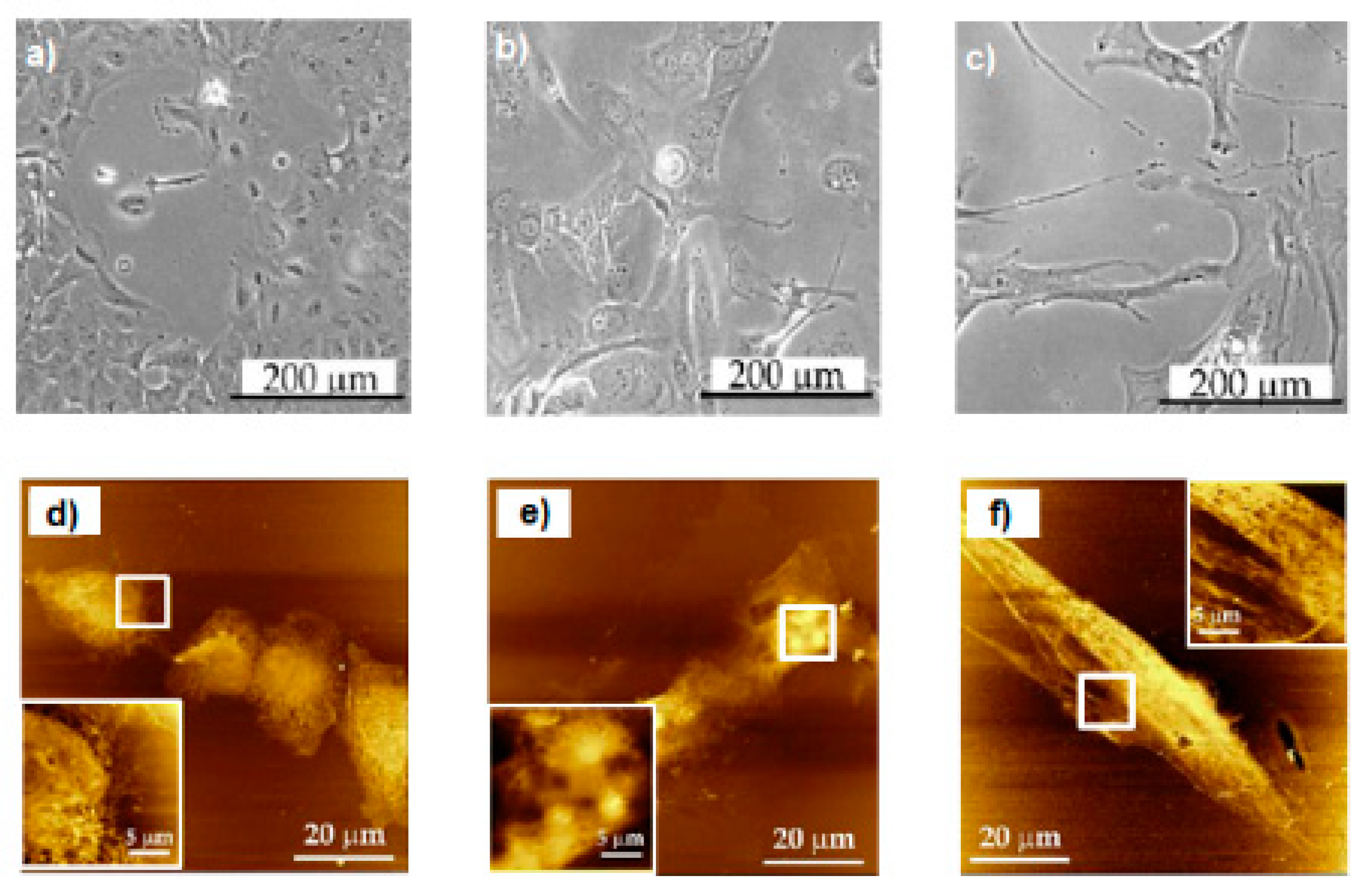
4.3.4. Imaging of Various Cell Lines
5. Discussion and Conclusions
Author Contributions
Funding
Acknowledgments
Conflicts of Interest
References
- Attwood, D.T. Soft X-rays and Extreme Ultraviolet Radiation; Cambridge University Press (CUP): Cambridge, UK, 1999. [Google Scholar]
- Rumsby, P.T. Laser produced plasmas as intense X-ray sources for microscopy at the Central Laser Facility. J. Microsc. 1985, 138, 245–265. [Google Scholar] [CrossRef]
- NBSP. International Organization for Standardization (ISO). ISO 14813–1:2015. 2015. Available online: https://www.iso.org/obp/ui/#iso:std:iso:14813:-1:ed-2:v1:en (accessed on 26 October 2020).
- Kördel, M.; Dehlinger, A.; Seim, C.; Vogt, U.; Fogelqvist, E.; Sellberg, J.A.; Stiel, H.; Hertz, H.M. Laboratory water-window X-ray microscopy. Optica 2020, 7, 658. [Google Scholar] [CrossRef]
- Hädrich, S.; Rothhardt, J.; Krebs, M.; Demmler, S.; Limpert, J.; Tünnermann, A. High photon flux and repetition rate table-top EUV sources based on ultrashort pulse fiber lasers. In Proceedings of the 2015 IEEE Photonics Conference (IPC), Reston, VA, USA, 4–8 October 2015; pp. 72–73. [Google Scholar]
- Ojeda, J.; Arrell, C.A.; Grilj, J.; Frassetto, F.; Mewes, L.; Zhang, H.; Van Mourik, F.; Poletto, L.; Chergui, M. Harmonium: A pulse preserving source of monochromatic extreme ultraviolet (30–110 eV) radiation for ultrafast photoelectron spectroscopy of liquids. Struct. Dyn. 2016, 3, 023602. [Google Scholar] [CrossRef] [PubMed]
- Spiller, E.; Segmüller, A.; Rife, J.; Haelbich, R. Controlled fabrication of multilayer soft-X-ray mirrors. Appl. Phys. Lett. 1980, 37, 1048–1050. [Google Scholar] [CrossRef]
- Ortega, R.; Bohic, S.; Tucoulou, R.; Somogyi, A.; Devès, G. Microchemical element imaging of yeast and human cells using synchrotron X-ray microprobe with Kirkpatrick−Baez optics. Anal. Chem. 2004, 76, 309–314. [Google Scholar] [CrossRef] [PubMed]
- Snigirev, A.; Kohn, V.G.; Snigireva, I.; Lengeler, B. A compound refractive lens for focusing high-energy X-rays. Nat. Cell Biol. 1996, 384, 49–51. [Google Scholar] [CrossRef]
- Kang, H.C.; Yan, H.; Winarski, R.P.; Holt, M.V.; Maser, J.; Liu, C.; Conley, R.; Vogt, S.; Macrander, A.T.; Stephenson, G.B. Focusing of hard x-rays to 16 nanometers with a multilayer Laue lens. Appl. Phys. Lett. 2008, 92, 221114. [Google Scholar] [CrossRef] [Green Version]
- Chao, W.; Fischer, P.; Tyliszczak, T.; Rekawa, S.; Anderson, E.; Naulleau, P. Real space soft X-ray imaging at 10 nm spatial resolution. Opt. Express 2012, 20, 9777–9783. [Google Scholar] [CrossRef] [PubMed]
- Legall, H.; Blobel, G.; Stiel, H.; Sandner, W.; Seim, C.; Takman, P.; Martz, D.H.; Selin, M.; Vogt, U.; Hertz, H.M.; et al. Compact X-ray microscope for the water window based on a high brightness laser plasma source. Opt. Express 2012, 20, 18362–18369. [Google Scholar] [CrossRef] [PubMed]
- Yase, S.; Nagaya, K.; Mizoguchi, Y.; Yao, M.; Fukuzawa, H.; Motomura, K.; Yamada, A.; Ma, R.; Ueda, K.; Saito, N.; et al. Crossover in the photoionization processes of neon clusters with increasing EUV free-electron-laser intensity. Phys. Rev. A 2013, 88, 043203. [Google Scholar] [CrossRef]
- Kashiwagi, S.; Kato, R.; Oyama, T.G.; Sakaue, K.; Masuda, A.; Nomoto, T.; Gowa, T.; Washio, M.; Kuroda, R.; Urakawa, J. Development of compact coherent EUV source based on laser Compton scattering. Radiat. Phys. Chem. 2009, 78, 1112–1115. [Google Scholar] [CrossRef]
- Rösner, B.; Koch, F.; Döring, F.; Guzenko, V.A.; Meyer, M.; Ornelas, J.L.; Späth, A.; Fink, R.H.; Stanescu, S.; Swaraj, S.; et al. 7 nm Spatial Resolution in Soft X-ray Microscopy. Microsc. Microanal. 2018, 24, 272–273. [Google Scholar] [CrossRef] [Green Version]
- CXRO-Center for X-ray Optics Database. Available online: http://henke.lbl.gov/optical_constants/ (accessed on 24 October 2020).
- Wachulak, P.; Bartnik, A.; Fiedorowicz, H.; Panek, D.; Bruza, P. Imaging of nanostructures with sub-100 nm spatial resolution using a desktop EUV microscope. Appl. Phys. A 2012, 109, 105–111. [Google Scholar] [CrossRef] [Green Version]
- Wachulak, P.; Torrisi, A.; Bartnik, A.; Węgrzyński, Ł.; Fok, T.; Jarocki, R.; Kostecki, J.; Szczurek, M.; Fiedorowicz, H. Fresnel zone plate telescope for condenser alignment in water-window microscope. J. Opt. 2015, 17, 055606. [Google Scholar] [CrossRef]
- Wachulak, P.; Węgrzyński, Ł.; Zápražný, Z.; Bartnik, A.; Fok, T.; Jarocki, R.; Kostecki, J.; Szczurek, M.; Korytár, D.; Fiedorowicz, H. Extreme ultraviolet tomography using a compact laser-plasma source for 3D reconstruction of low density objects. Opt. Lett. 2014, 39, 532–535. [Google Scholar] [CrossRef]
- Park, I.Y.; Choi, J.; Lee, D.-H.; Han, S.; Kim, S.; Kim, S.-W. Generation of EUV radiation by plasmonic field enhancement using nano-structured bowties and funnel-waveguides. Ann. Phys. 2012, 525, 87–96. [Google Scholar] [CrossRef]
- Li, L.; Liu, X.; Pal, S.; Wang, S.; Ober, C.K.; Giannelis, E.P. Extreme ultraviolet resist materials for sub-7 nm patterning. Chem. Soc. Rev. 2017, 46, 4855–4866. [Google Scholar] [CrossRef]
- DiCicco, D.S.; Kim, D.; Rosser, R.; Suckewer, S. First stage in the development of a soft-x-ray reflection imaging microscope in the Schwarzschild configuration using a soft-X-ray laser at 182 nm. Opt. Lett. 1992, 17, 157–159. [Google Scholar] [CrossRef]
- Vaschenko, G.; Brizuela, F.; Brewer, C.; Grisham, M.; Mancini, H.; Menoni, C.S.; Marconi, M.C.; Rocca, J.J.; Chao, W.; Liddle, J.A.; et al. Nanoimaging with a compact extreme-ultraviolet laser. Opt. Lett. 2005, 30, 2095–2097. [Google Scholar] [CrossRef] [Green Version]
- Brewer, C.A.; Brizuela, F.; Wachulak, P.; Martz, D.H.; Chao, W.; Anderson, E.H.; Attwood, D.T.; Vinogradov, A.V.; Artyukov, I.A.; Ponomareko, A.G.; et al. Single-shot extreme ultraviolet laser imaging of nanostructures with wavelength resolution. Opt. Lett. 2008, 33, 518–520. [Google Scholar] [CrossRef] [Green Version]
- Wachulak, P.; Marconi, M.C.; Bartels, R.A.; Menoni, C.S.; Rocca, J.J. Sub-50nm extreme ultraviolet holographic imaging. In Proceedings of the Holography: Advances and Modern Trends; SPIE-International Society of Optical Engineering: Bellingham, WA, USA, 2009; Volume 7358, p. 735806. [Google Scholar]
- Kasuya, K.; Kolacek, K.; Schmidt, J.; Frolov, O.; Straus, J.; Matejicek, J.; Choukoulov, A.; Motokoshi, S.; Nakai, M.; Tokunaga, K. Surface changes of structural materials ablated with nanosecond EUV laser light. In Proceedings of the 16th Symposium on Advanced Photon Research, Kizugawa, Kyoto, Japan, 15–16 October 2015. [Google Scholar] [CrossRef]
- Brewer, C.; Vaschenko, G.; Brizuela, F.; Wang, Y.; Larotonda, M.A.; Luther, B.M.; Marconi, M.C.; Rocca, J.J.; Menoni, C.S.; Chao, W.; et al. Sub-38 nm resolution microscopy with a tabletop 13 nm wavelength laser. In Proceedings of the 2006 Conference on Lasers and Electro-Optics and 2006 Quantum Electronics and Laser Science Conference, Long Beach, CA, USA, 21–26 May 2006; Volume 31, pp. 1–2. [Google Scholar] [CrossRef]
- Mey, T.; Rein, M.; Großmann, P.; Mann, K. Brilliance improvement of laser-produced soft x-ray plasma by a barrel shock. New J. Phys. 2012, 14, 073045. [Google Scholar] [CrossRef]
- Wieland, M.; Spielmann, C.; Kleineberg, U.; Westerwalbesloh, T.; Heinzmann, U.; Wilhein, T.; Spielmann, C. Toward time-resolved soft X-ray microscopy using pulsed fs-high-harmonic radiation. Ultramicroscopy 2005, 102, 93–100. [Google Scholar] [CrossRef] [PubMed]
- Kishimoto, M.; Tanaka, M.; Tai, R.; Sukegawa, K.; Kado, M.; Hasegawa, N.; Tang, H.; Kawachi, T.; Lu, P.; Nagashima, K.; et al. Development of soft X-ray microscopy system using X-ray laser in JAERI Kansai. J. Phys. IV Fr. 2003, 104, 141–143. [Google Scholar] [CrossRef]
- Zürch, M.; Jung, R.; Späth, C.; Tümmler, J.; Guggenmos, A.; Attwood, D.; Kleineberg, U.; Stiel, H.; Spielmann, C. Transverse coherence limited coherent diffraction imaging using a Molybdenum Soft X-ray Laser Pumped at Moderate Pump Energies. Sci. Rep. 2017, 7, 5314. [Google Scholar] [CrossRef] [Green Version]
- Cardin, V.; Schimdt, B.E.; Thiré, N.; Beaulieu, S.; Wanie, V.; Negro, M.; Vozzi, C.; Tosa, V.; Légaré, F. Self-channelled high harmonic generation of water window soft X-rays. J. Phys. B At. Mol. Opt. Phys. 2018, 51, 174004. [Google Scholar] [CrossRef]
- Frank, V.; Chushkin, Y.; Fröhlich, B.; Abuillan, W.; Rieger, H.; Becker, A.S.; Yamamoto, A.; Rossetti, F.F.; Kaufmann, S.; Lanzer, M.; et al. Lensless tomographic imaging of near surface structures of frozen hydrated malaria-infected human erythrocytes by coherent X-ray diffraction microscopy. Sci. Rep. 2017, 7, 14081. [Google Scholar] [CrossRef] [Green Version]
- Treacher, D.J.; Lloyd, D.T.; Wiegandt, F.; O’Keeffe, K.; Hooker, S.M. Optimised XUV holography using spatially shaped high harmonic beams. Opt. Express 2019, 27, 29016–29025. [Google Scholar] [CrossRef]
- Chen, Z.; Odstrcil, M.; Jiang, Y.; Han, Y.; Chiu, M.-H.; Li, L.-J.; Muller, D.A. Mixed-state electron ptychography enables sub-angstrom resolution imaging with picometer precision at low dose. Nat. Commun. 2020, 11, 2994. [Google Scholar] [CrossRef]
- Helk, T.; Zürch, M.; Spielmann, C. Perspective: Towards single shot time-resolved microscopy using short wavelength table-top light sources. Struct. Dyn. 2019, 6, 010902. [Google Scholar] [CrossRef]
- Wenz, J.; Schleede, S.; Khrennikov, K.; Bech, M.; Thibault, P.; Heigoldt, M.; Pfeiffer, F.; Karsch, S. Quantitative X-ray phase-contrast microtomography from a compact laser-driven betatron source. Nat. Commun. 2015, 6, 7568. [Google Scholar] [CrossRef]
- Johansson, G.A.; Holmberg, A.; Hertz, H.M.; Berglund, M. Design and performance of a laser-plasma-based compact soft X-ray microscope. Rev. Sci. Instrum. 2002, 73, 1193–1197. [Google Scholar] [CrossRef] [Green Version]
- Benk, M.; Bergmann, K.; Schäfer, D.; Wilhein, T. Compact soft X-ray microscope using a gas-discharge light source. Opt. Lett. 2008, 33, 2359–2361. [Google Scholar] [CrossRef] [PubMed]
- Legall, H.; Stiel, H.; Blobel, G.; Seim, C.; Baumann, J.; Yulin, S.; Esser, D.; Hoefer, M.; Wiesemann, U.; Wirtz, M.; et al. A compact laboratory transmission X-ray microscope for the water window. In Proceedings of the Journal of Physics: Conference Series; IOP Publishing: Bristol, UK, 2013; Volume 463, pp. 5–10. [Google Scholar]
- Martz, D.H.; Selin, M.; Von Hofsten, O.; Fogelqvist, E.; Holmberg, A.; Vogt, U.; LeGall, H.; Blobel, G.; Seim, C.; Stiel, H.; et al. High average brightness water window source for short-exposure cryomicroscopy. Opt. Lett. 2012, 37, 4425–4427. [Google Scholar] [CrossRef] [PubMed]
- Müller, M.; Mey, T.; Niemeyer, J.; Mann, K. Table-top soft X-ray microscope using laser-induced plasma from a pulsed gas jet. Opt. Express 2014, 22, 23489–23495. [Google Scholar] [CrossRef] [Green Version]
- Yu, Y.-S.; Farmand, M.; Kim, C.; Liu, Y.; Grey, C.P.; Strobridge, F.C.; Tyliszczak, T.; Celestre, R.; Denes, P.; Joseph, J.; et al. Three-dimensional localization of nanoscale battery reactions using soft X-ray tomography. Nat. Commun. 2018, 9, 921. [Google Scholar] [CrossRef]
- Chiappi, M.; Conesa, J.J.; Pereiro, E.; Sorzano, C.O.S.; Rodríguez, M.J.; Henzler, K.; Schneider, G.; Chichón, F.J.; Carrascosa, J.L. Cryo-soft X-ray tomography as a quantitative three-dimensional tool to model nanoparticle:cell interaction. J. Nanobiotechnology 2016, 14, 15. [Google Scholar] [CrossRef] [Green Version]
- Harkiolaki, M.; Darrow, M.C.; Spink, M.C.; Kosior, E.; Dent, K.; Duke, E. Cryo-soft X-ray tomography: Using soft X-rays to explore the ultrastructure of whole cells. Emerg. Top. Life Sci. 2018, 2, 81–92. [Google Scholar] [CrossRef] [Green Version]
- Leontowich, A.F.; Berg, R.; Regier, C.N.; Taylor, D.M.; Wang, J.; Beauregard, D.; Geilhufe, J.; Swirsky, J.; Wu, J.; Karunakaran, C.; et al. Cryo scanning transmission X-ray microscope optimized for spectrotomography. Rev. Sci. Instrum. 2018, 89, 093704. [Google Scholar] [CrossRef]
- Yabashi, M.; Tanaka, H. The next ten years of X-ray science. Nat. Photon. 2017, 11, 12–14. [Google Scholar] [CrossRef]
- Kimura, T.; Joti, Y.; Shibuya, A.; Song, C.; Kim, S.; Tono, K.; Yabashi, M.; Tamakoshi, M.; Moriya, T.; Oshima, T.; et al. Imaging live cell in micro-liquid enclosure by X-ray laser diffraction. Nat. Commun. 2014, 5, 3052. [Google Scholar] [CrossRef] [Green Version]
- Fiedorowicz, H.; Bartnik, A.; Jarocki, R.; Rakowski, R.; Szczurek, M. Enhanced X-ray emission in the 1-keV range from a laser-irradiated gas puff target produced using the double-nozzle setup. Appl. Phys. A 2000, 70, 305–308. [Google Scholar] [CrossRef]
- Wachulak, P. Contributed Review: The novel gas puff targets for laser-matter interaction experiments. Rev. Sci. Instrum. 2016, 87, 091501. [Google Scholar] [CrossRef] [PubMed]
- Wachulak, P.; Bartnik, A.; Jarocki, R.; Fiedorowicz, H. Characterization of multi-jet gas puff targets for high-order harmonic generation using EUV shadowgraphy. Nucl. Instrum. Methods Phys. Res. Sect. B Beam Interact. Mater. Atoms 2012, 285, 102–106. [Google Scholar] [CrossRef]
- Rakowski, R.; Bartnik, A.; Fiedorowicz, H.; Jarocki, R.; Kostecki, J.; Mikolajczyk, J.; Szczurek, A.; Földes, I.; Tóth, Z.; Szczurek, M. Pulsed X-ray radiography of a gas jet target for laser–matter interaction experiments with the use of a CCD detector. Nucl. Instrum. Methods Phys. Res. Sect. A Accel. Spectrom. Detect. Assoc. Equip. 2005, 551, 139–144. [Google Scholar] [CrossRef]
- Adjei, D.; Ayele, M.G.; Wachulak, P.; Bartnik, A.; Węgrzyński, Ł.; Fiedorowicz, H.; Vyšín, L.; Wiecheć, A.; Lekki, J.; Kwiatek, W.; et al. Development of a compact laser-produced plasma soft X-ray source for radiobiology experiments. Nucl. Instrum. Methods Phys. Res. Sect. B Beam Interact. Mater. Atoms 2015, 364, 27–32. [Google Scholar] [CrossRef]
- Bartnik, A.; Fiedorowicz, H.; Wachulak, P. Spectral investigations of photoionized plasmas induced in atomic and molecular gases using nanosecond extreme ultraviolet (EUV) pulses. Phys. Plasmas 2014, 21, 073303. [Google Scholar] [CrossRef]
- Rakowski, R.; Bartnik, A.; Fiedorowicz, H.; Jarocki, R.; Kostecki, J.; Krzywiński, J.; Mikołajczyk, J.; Pína, L.; Ryć, L.; Szczurek, M.; et al. Metrology of Mo/Si multilayer mirrors at 13.5 nm with the use of a laser-produced plasma extreme ultraviolet (EUV) source based on a gas puff target. Opt. Appl. 2006, 36, 593–600. [Google Scholar]
- Wachulak, P.; Bartnik, A.; Jarocki, R.; Fok, T.; Węgrzyński, Ł.; Kostecki, J.; Szczurek, M.; Fiedorowicz, H. Study of uniformity of elongated plasma channels formed in gas puff targets using extreme ultraviolet and soft X-ray radiation. Laser Part. Beams 2015, 33, 293–298. [Google Scholar] [CrossRef]
- Wachulak, P.; Bartnik, A.; Kostecki, J.; Węgrzyński, Ł.; Fok, T.; Jarocki, R.; Szczurek, M.; Fiedorowicz, H. Extreme ultraviolet and soft X-ray imaging with compact, table top laser plasma EUV and SXR sources. Nucl. Instrum. Methods Phys. Res. Sect. B Beam Interact. Mater. Atoms 2015, 364, 40–48. [Google Scholar] [CrossRef]
- Torrisi, A.; Węgrzyński, Ł.; Fok, T.; Vondrová, Š.; Turňová, J.; Bartosewicz, B.; Wachulak, P.; Bartnik, A.; Parkman, T.; Jankiewicz, B.; et al. A stand-alone compact EUV microscope based on gas-puff target source. J. Microsc. 2016, 265, 251–260. [Google Scholar] [CrossRef]
- Wachulak, P.W.; Torrisi, A.; Krauze, W.; Bartnik, A.; Kostecki, J.; Maisano, M.; Sciortino, A.M.; Fiedorowicz, H. A “water window” tomography based on a laser-plasma double-stream gas-puff target soft X-ray source. Appl. Phys. A 2019, 125, 70. [Google Scholar] [CrossRef]
- Wachulak, P.W.; Torrisi, A.L.; Nawaz, M.F.; Adjei, D.; Bartnik, A.; Kostecki, J.; Wegrzynski, Ł.; Vondrová, Š.; Turňová, J.; Fok, T.; et al. A compact “water-window” microscope with 60-nm spatial resolution based on a double stream gas-puff target and Fresnel zone plate optics. In Proceedings of the EUV and X-ray Optics: Synergy between Laboratory and Space; SPIE-International Society for Optical Engineering: Bellingham, WA, USA, 2015; p. 95100M. [Google Scholar]
- Werner, S.; Rehbein, S.; Guttmann, P.; Schneider, G. Three-dimensional structured on-chip stacked zone plates for nanoscale X-ray imaging with high efficiency. Nano Res. 2014, 7, 528–535. [Google Scholar] [CrossRef]
- Lübcke, A.; Braenzel, J.; Dehlinger, A.; Schnürer, M.; Stiel, H.; Guttmann, P.; Rehbein, S.; Schneider, G.; Werner, S.; Kemmler, R.; et al. Soft X-ray nanoscale imaging using a sub-pixel resolution charge coupled device (CCD) camera. Rev. Sci. Instrum. 2019, 90, 043111. [Google Scholar] [CrossRef] [PubMed]
- Kado, M.; Daido, H.; Yamamoto, Y.; Shinohara, K.; Richardson, M.C. Development of a laser plasma X-ray microscope to observe live hydrated biological specimens. Laser Phys. Lett. 2006, 3, 205–207. [Google Scholar] [CrossRef]
- Sakdinawat, A.; Attwood, D.T. Nanoscale X-ray imaging. Nat. Photon. 2010, 4, 840–848. [Google Scholar] [CrossRef]
- Kado, M.; Kishimoto, M.; Tamotsu, S.; Yasuda, K.; Shinohara, K. In situ observation of cellular organelles with a contact x-ray microscope. In Proceedings of the Journal of Physics: Conference Series; IOP Publishing: Bristol, UK, 2013; Volume 463, p. 012056. [Google Scholar]
- Majima, T. Soft X-ray imaging of living cells in water: Flash contact soft X-ray microscope. TrAC Trends Anal. Chem. 2004, 23, 520–526. [Google Scholar] [CrossRef]
- Ayele, M.; Wachulak, P.; Czwartos, J.; Adjei, D.; Bartnik, A.; Węgrzyński, Ł.; Szczurek, M.; Pina, L.; Fiedorowicz, H. Development and characterization of a laser-plasma soft X-ray source for contact microscopy. Nucl. Instrum. Methods Phys. Res. Sect. B Beam Interact. Mater. Atoms 2017, 411, 35–43. [Google Scholar] [CrossRef]
- Fiedorowicz, H.; Bartnik, A. X-ray laser emission from a laser-irradiated gas puff target. Bull. Pol. Acad. Sci. Tech. Sci. 2005, 53, 103–111. [Google Scholar] [CrossRef]
- Torrisi, A. Soft X-ray and Extreme Ultraviolet Nanoscale Imaging Using Compact Laser-Plasma Sources based on a Double Stream Gas-Puff Target and Fresnel Optics. Ph.D. Thesis, Military University of Technology, Warsaw, Poland, 10 April 2017. [Google Scholar]
- Wachulak, P.; Bartnik, A.; Fiedorowicz, H.; Rudawski, P.; Jarocki, R.; Kostecki, J.; Szczurek, M. “Water window” compact, table-top laser plasma soft X-ray sources based on a gas puff target. Nucl. Instrum. Methods Phys. Res. Sect. B Beam Interact. Mater. Atoms 2010, 268, 1692–1700. [Google Scholar] [CrossRef]
- Wachulak, P.; Torrisi, A.; Bartnik, A.; Węgrzyński, Ł.; Fok, T.; Fiedorowicz, H. A desktop extreme ultraviolet microscope based on a compact laser-plasma light source. Appl. Phys. A 2016, 123, 25. [Google Scholar] [CrossRef] [Green Version]
- Marconi, M.C.; Wachulak, P. Extreme ultraviolet lithography with table top lasers. Prog. Quantum Electron. 2010, 34, 173–190. [Google Scholar] [CrossRef]
- Kelly, R.L. Atomic and ionic spectrum lines below 2000 Angstroms: Hydrogen through Krypton Part I (H-Cr). J. Phys. Chem. Ref. Data 1987, 16, 1–404. [Google Scholar]
- Heck, J.M.; Attwood, D.T.; Meyer-Ilse, W.; Anderson, E.H. Resolution determination in X-ray microscopy: An analysis of the effects of partial coherence and illumination spectrum. J. X-Ray Sci. Technol. 1998, 8, 95–104. [Google Scholar]
- Torrisi, A.; Wachulak, P.; Bartnik, A.; Węgrzyński, Ł.; Fok, T.; Fiedorowicz, H. Development and optimization of a “water window” microscope based on a gas-puff target laser-produced plasma source. EPJ Web Conf. 2018, 167, 3002. [Google Scholar] [CrossRef] [Green Version]
- Wachulak, P.; Torrisi, A.; Ayele, M.; Czwartos, J.; Bartnik, A.; Węgrzyński, Ł.; Fok, T.; Parkman, T.; Salačová, Š.; Turňová, J.; et al. Bioimaging using full field and contact EUV and SXR microscopes with nanometer spatial resolution. Appl. Sci. 2017, 7, 548. [Google Scholar] [CrossRef] [Green Version]
- Wachulak, P.; Torrisi, A.; Nawaz, M.F.; Bartnik, A.; Adjei, D.; Vondrová, Š.; Turňová, J.; Jančarek, A.; Limpouch, J.; Vrbová, M.; et al. A compact “Water Window” microscope with 60 nm spatial resolution for applications in biology and nanotechnology. Microsc. Microanal. 2015, 21, 1214–1223. [Google Scholar] [CrossRef]
- Engström, A. Microradiography and roentgen microscopy. In Encyclopedia of Medical Radiology; Springer Science and Business Media LLC: Berlin, Germany, 1967; Volume 3, pp. 677–693. [Google Scholar]
- Torrisi, A.; Wachulak, P.; Nawaz, M.F.; Bartnik, A.; Węgrzyński, L.; Jancarek, A.; Fiedorowicz, H. Characterization and optimization of images acquired by a compact soft X-ray microscope based on a double stream gas-puff target source. J. Instrum. 2016, 11, C04003. [Google Scholar] [CrossRef]
- Wachulak, P.; Torrisi, A.; Bartnik, A.; Adjei, D.; Kostecki, J.; Wegrzynski, L.; Jarocki, R.; Szczurek, M.; Fiedorowicz, H. Desktop water window microscope using a double-stream gas puff target source. Appl. Phys. A 2015, 118, 573–578. [Google Scholar] [CrossRef]
- Ayele, M.G. Soft X-ray Contact Microscopy Using a Laser-Plasma Light Source Based on a Gas Puff Target. Ph.D. Thesis, Military University of Technology, Warsaw, Poland, 17 April 2018. [Google Scholar]
- Sousa, A.A.; Leapman, R.D. Development and application of STEM for the biological sciences. Ultramicroscopy 2012, 123, 38–49. [Google Scholar] [CrossRef] [Green Version]
- Pu, S.; Gong, C.; Robertson, A.W. Liquid cell transmission electron microscopy and its applications. R. Soc. Open Sci. 2020, 7, 191204. [Google Scholar] [CrossRef] [Green Version]
- Jacobsen, C.; Kirz, J. X-ray microscopy with synchrotron radiation. Nat. Genet. 1998, 5, 650–653. [Google Scholar] [CrossRef] [PubMed]
- Ayele, M.; Czwartos, J.; Adjei, D.; Wachulak, P.; Ahad, I.U.; Bartnik, A.; Węgrzyński, Ł.; Szczurek, M.; Jarocki, R.; Fiedorowicz, H.; et al. Contact microscopy using a compact laser produced plasma soft X-ray Source. Acta Phys. Pol. A 2016, 129, 237–240. [Google Scholar] [CrossRef]
- Osuchowska, P.N.; Wachulak, P.; Nowak-Stępniowska, A.; Bartnik, A.; Gnanachandran, K.; Lekka, M.; Czwartos, J.; Fiedorowicz, H.; Trafny, E.A. Imaging of cell structures using optimized soft X-ray contact microscopy. Appl. Sci. 2020, 10, 6895. [Google Scholar] [CrossRef]
- Wachulak, P.; Torrisi, A.; Ayele, M.; Czwartos, J.; Bartnik, A.; Jarocki, R.; Kostecki, J.; Szczurek, M.; Wegrzyński, Ł.; Fiedorowicz, H. Nanoscale imaging using a compact laser plasma source of soft X-rays and Extreme Ultraviolet (EUV). In Springer Proceedings in Physics; Springer Science and Business Media LLC: Berlin, Germany, 2018; Volume 202, pp. 251–260. [Google Scholar]
- Adjei, D.; Wiecheć, A.; Wachulak, P.; Ayele, M.G.; Lekki, J.; Kwiatek, W.; Bartnik, A.; Davidkova, M.; Vyšín, L.; Juha, L.; et al. DNA strand breaks induced by soft X-ray pulses from a compact laser plasma source. Radiat. Phys. Chem. 2016, 120, 17–25. [Google Scholar] [CrossRef]
- Wachulak, P.; Torrisi, A.; Ayele, M.; Bartnik, A.; Węgrzyński, Ł.; Fok, T.; Czwartos, J.; Fiedorowicz, H. Nanoimaging using soft X-ray and EUV sources based on double stream gas puff targets. Acta Phys. Pol. A 2018, 133, 271–276. [Google Scholar] [CrossRef]
- Wachulak, P.; Torrisi, A.; Ayele, M.; Bartnik, A.; Czwartos, J.; Węgrzyński, Ł.; Fok, T.; Fiedorowicz, H. Nanoimaging using soft X-ray and EUV laser-plasma sources. EPJ Web Conf. 2018, 167, 3001. [Google Scholar] [CrossRef] [Green Version]
- Torrisi, A.; Wachulak, P.W.; Bartnik, A.; Węgrzyński, Ł.; Fok, T.; Fiedorowicz, H. Biological and material science applications of EUV and SXR nanoscale imaging systems based on double stream gas puff target laser plasma sources. Nucl. Instrum. Methods Phys. Res. Sect. B Beam Interact. Mater. Atoms 2017, 411, 29–34. [Google Scholar] [CrossRef]
- Wachulak, P.; Torrisi, A.; Krauze, W.; Bartnik, A.; Kostecki, J.; Maisano, M.; Fiedorowicz, H. Tomographic imaging using a compact soft X-ray microscope based on a laser plasma light source. In EUV and X-ray Optics: Synergy between Laboratory and Space VI; SPIE: Bellingham, WA, USA, 2019; Volume 11032, p. 110320N. [Google Scholar] [CrossRef]
- ImageJ. Available online: http://imagej.nih.gov/ij/ (accessed on 20 May 2009).
- MessaoudiI, C.; Boudier, T.; Sorzano, C.O.S.; Marco, S. TomoJ: Tomography software for three-dimensional reconstruction in transmission electron microscopy. BMC Bioinform. 2007, 8, 288. [Google Scholar] [CrossRef] [Green Version]
- Krauze, W.; Makowski, P.; Kujawińska, M.; Kuś, A. Generalized total variation iterative constraint strategy in limited angle optical diffraction tomography. Opt. Express 2016, 24, 4924–4936. [Google Scholar] [CrossRef]
- Devaney, A.J. Inverse-scattering theory within the Rytov approximation. Opt. Lett. 1981, 6, 374–376. [Google Scholar] [CrossRef]
- Chambolle, A.; Pock, T. A first-order primal-dual algorithm for convex problems with applications to imaging. J. Math. Imaging Vis. 2011, 40, 120–145. [Google Scholar] [CrossRef] [Green Version]
- Bleiner, D.; Staub, F.; Guzenko, V.; Ekinci, Y.; Balmer, J.E. Evaluation of lab-scale EUV microscopy using a table-top laser source. Opt. Commun. 2011, 284, 4577–4583. [Google Scholar] [CrossRef]
- Eschen, W.; Tadesse, G.K.; Klas, R.; Tschernajew, M.; Tuitje, F.; Spielmann, C.; Tünnermann, A.; Limpert, J.; Rothhardt, J. High resolution ptychographic coherent diffractive imaging using table-top XUV sources. In Imaging and Applied Optics 2018 (3D, AO, AIO, COSI, DH, IS, LACSEA, LS&C, MATH, pcAOP); Optical Society of America: Washington, DC, USA, 2018; p. JM3E.4. [Google Scholar] [CrossRef]
- Keunecke, M.; Möller, C.; Schmitt, D.; Nolte, H.; Jansen, G.S.M.; Reutzel, M.; Gutberlet, M.; Halasi, G.; Steil, D.; Steil, S.; et al. Time-resolved momentum microscopy with a 1 MHz high-harmonic extreme ultraviolet beamline. Rev. Sci. Instrum. 2020, 91, 063905. [Google Scholar] [CrossRef] [PubMed]
- Nawaz, M.; Nevrkla, M.; Jancarek, A.; Torrisi, A.; Parkman, T.; Turnova, J.; Stolcova, L.; Vrbova, M.; Limpouch, J.; Pina, L.; et al. Table-top water-window soft X-ray microscope using a Z-pinching capillary discharge source. J. Instrum. 2016, 11, P07002. [Google Scholar] [CrossRef]
- Popmintchev, D.; Galloway, B.R.; Chen, M.-C.; Dollar, F.; Mancuso, C.A.; Hankla, A.; Miaja-Avila, L.; O’Neil, G.; Shaw, J.M.; Fan, G.; et al. Near- and extended-edge X-ray-absorption fine-structure spectroscopy using ultrafast coherent high-order harmonic supercontinua. Phys. Rev. Lett. 2018, 120, 093002. [Google Scholar] [CrossRef] [PubMed] [Green Version]
- Hanne, J.; Falk, H.J.; Görlitz, F.; Hoyer, P.; Engelhardt, J.; Sahl, S.J.; Hell, S.W. STED nanoscopy with fluorescent quantum dots. Nat. Commun. 2015, 6, 7127. [Google Scholar] [CrossRef] [Green Version]


Publisher’s Note: MDPI stays neutral with regard to jurisdictional claims in published maps and institutional affiliations. |
© 2020 by the authors. Licensee MDPI, Basel, Switzerland. This article is an open access article distributed under the terms and conditions of the Creative Commons Attribution (CC BY) license (http://creativecommons.org/licenses/by/4.0/).
Share and Cite
Torrisi, A.; Wachulak, P.W.; Bartnik, A.; Węgrzyński, Ł.; Fok, T.; Fiedorowicz, H. Biological Applications of Short Wavelength Microscopy Based on Compact, Laser-Produced Gas-Puff Plasma Source. Appl. Sci. 2020, 10, 8338. https://doi.org/10.3390/app10238338
Torrisi A, Wachulak PW, Bartnik A, Węgrzyński Ł, Fok T, Fiedorowicz H. Biological Applications of Short Wavelength Microscopy Based on Compact, Laser-Produced Gas-Puff Plasma Source. Applied Sciences. 2020; 10(23):8338. https://doi.org/10.3390/app10238338
Chicago/Turabian StyleTorrisi, Alfio, Przemysław W. Wachulak, Andrzej Bartnik, Łukasz Węgrzyński, Tomasz Fok, and Henryk Fiedorowicz. 2020. "Biological Applications of Short Wavelength Microscopy Based on Compact, Laser-Produced Gas-Puff Plasma Source" Applied Sciences 10, no. 23: 8338. https://doi.org/10.3390/app10238338