


Abstract
The interaction between the edge-plasma in a fusion reactor and the surrounding first-wall components is one of the main issues for the realisation of fusion energy power plants. The EUROfusion Work Package on plasma-facing components addresses the key areas of plasma-surface interaction in view of ITER and DEMO operation, which are mostly related to material erosion, surface damage and fuel retention. These aspects are both investigated experimentally (in tokamaks, linear plasma devices and lab experiments) and by modelling. Here, selective results regarding the main research topics are presented: in the area of tungsten (W) surface modifications, the interplay between W fuzz formation and W fuzz erosion depends strongly on the local plasma and surface conditions, as demonstrated by tokamak experiments. Complementary, experimental findings on the dependence of erosion on the surface structure in lab-scale experiments have led to the successful implementation of surface structure effects in numerical modelling. The qualification of ITER-like monoblocks at high fluences of up to 1031 D m−2 in linear plasma facilities has shown no visible damages at cold plasma conditions. However, experiments with simultaneous plasma and pulsed heat loading (edge-localized modes simulations) show that synergistic effects can lower the W damage thresholds. Additionally, fuel retention studies show that nitrogen as a plasma impurity increases the fuel retention in W, and that deuterium implanted in the surface of W is capable of stabilizing displacement damages caused by neutron damage. Finally, the implications of these results on ITER and DEMO operation are discussed and an outlook on follow-up experiments is given: the results indicate that there are possible impacts on the ITER divertor lifetime and tritium removal. Other areas like the divertor shaping and the erosion need additional investigations in the future to quantify the impact on ITER and DEMO operation.
Export citation and abstract BibTeX RIS

Original content from this work may be used under the terms of the Creative Commons Attribution 4.0 licence. Any further distribution of this work must maintain attribution to the author(s) and the title of the work, journal citation and DOI.
1. Introduction
The EUROfusion [1] WP PFC (Work Package on plasma-facing components) focuses on critical plasma-surface interaction studies and components qualification in view of upcoming ITER operation and in preparation for DEMO exhaust solutions. Consequently, the main research topics within WP PFC are also oriented along the research requirements to support the ITER Research Plan [2, 3]. For the area of plasma–wall-interaction (PWI) issues, this includes primarily the qualification of wall materials under hydrogen or helium plasma loads, including the influence of plasma impurities (seeding gases envisaged for ITER operation) or ELM heat loads during plasma exposure [3].
WP PFC is addressing the three key areas which ensure a safe and efficient use of PFCs for ITER and DEMO: the lifetime aspect (material properties, material erosion, surface damage), the safety aspect (fuel retention, neutron damage and its impact on retention, seeding, dust production), and the aspect of predictive modelling for those processes in the local and global manner (code validation for ITER and DEMO). The bridge between linear plasma devices [4–7], particle and heat load facilities [8–10], and the WEST tokamak [11] is ensured via the application of theoretical interpretation and numerical interpretative modelling of experimental findings. Additional information is obtained by dedicated laboratory experiments addressing the physics behind the different PSI processes and the power handling capabilities of PFCs. Not only the overall effect of exposure to a tokamak plasma is covered by post-mortem analysis of components, also the detailed physics processes on atomistic level is studied, modelled, and transferred to larger scale models. These models are used for predictions of material migration, fuel retention and dust production in ITER and DEMO (with PSI codes such as ERO [12] and WallDYN [13]).
In the following sections, selected recent key results from the WP PFC program are presented. The goal of this paper is to summarize the results that have been reached within WP PFC, and to discuss their impact on future follow-up studies as well as on the ITER and DEMO operation and design. Regarding the list of research areas covered by this summary paper, we focus on the helium–tungsten (He–W) interaction with respect to surface modifications (W fuzz) during tokamak exposure (section 2.1), the impact of the surface structure on erosion (section 2.2), the qualification of ITER-like monoblocks (MBs) (section 2.3), and finally the fuel retention in W under the influence of impurities and neutron damage (section 2.4).
2. Key results
2.1. Helium–tungsten interaction
Helium (He) as a plasma impurity is of great interest when investigating plasma–wall interactions since it will be present in a fusion plasma as an intrinsic impurity (due to the fusion reaction of deuterium (D) and tritium (T)). It is well-known that He also has an impact on the surface morphology during plasma exposure, for example by inducing tungsten (W) fuzz [14]. Both the detailed mechanisms of W fuzz growth [15] as well as the conditions under which it occurs [16] have already been investigated. However, systematic studies are also required in tokamaks since the complex interaction and synergistic effects of parameters can influence the formation of W fuzz. Here we show some of the results from high flux experiments at AUG with He pre-damaged bulk W [17–19], and from the dedicated He campaign on W-coated MBs in the full W tokamak WEST [11]. The goal of these experiments is the prediction of the He–W interaction in the different phases of ITER, where He is present both during the pre-fusion-power operation phase with pure He plasma scenarios, as well as during fusion power operation in DT with the resulting He ash [2].
At AUG [17], samples have been exposed to H-mode (for eroding W fuzz) and L-mode (for growing W fuzz) plasmas, after they have been pre-damaged in the linear plasma facility PSI-2 [20] or the ion beam facility GLADIS [10]. While GLADIS has exposed the samples to a high energy (15 keV) H ion beam with 6 at.% of He at surface temperatures of up to 2000 K, the He plasma at PSI-2 has a lower impact energy of 100 eV for the He ions, and a lower sample surface temperature of 1200 K. With these parameters, both facilities can produce samples with He nanobubbles and W fuzz/nanostructure. This provides the target for studies related to W fuzz growth from W with He nanobubbles and W fuzz erosion from full grown nanostructures.
The pre-damaged samples have been exposed to He plasmas at the outer strike point of ASDEX-Upgrade utilising the DIM-II manipulator [21]. The samples were oriented in lines along the poloidal direction, allowing the investigation of the surface structure at several points at, above and below the strike line. The plasma and surface conditions around the strike-line matches the required conditions for W fuzz formation and growth [22]. The figures 1(a)–(d) (reproduced with permission from [17]-slides 11, 13, 15) show SEM images of the W samples at different magnifications before and after the tokamak exposure.
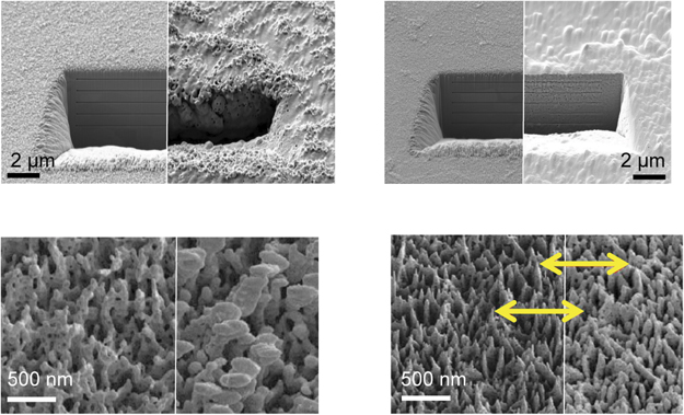
Figure 1. (a) SEM image of W divertor sample, before (left) and after (right) exposure, exposure conditions: AUG H-Mode, ELMs, above strike line. (b) SEM image of W divertor sample, before (left) and after (right) exposure, exposure conditions: AUG H-Mode, ELMs, at strike line. (c) SEM image of W divertor sample, before (left) and after (right) exposure, exposure conditions: AUG H-Mode, ELMs, below strike line. (d) SEM image of W divertor sample, before (left) and after (right) exposure, exposure conditions: AUG L-Mode, at strike line. Reprinted from [17], Copyright (2021), with permission from Elsevier.
Download figure:
Standard image High-resolution imageIn figure 1(a), the sample location above the strike line exhibits clear formation of new W fuzz on the sample. The focussed ion beam (FIB) cut visible in figures 1(a) and (b) were used as marker scales to measure the erosion of W during the exposure at ASDEX-Upgrade. The FIB cuts also show that W fuzz is not only forming on the direct surface of the sample, but also inside the FIB cut. In figure 1(b), which shows the sample that was located directly at the strike line, the erosion of the pre-existing W fuzz is observed. With the marker scale (distance between scale markings: 1 μm), a surface erosion of 200 nm was measured.
Strong arcing was observed at and below the strike line during the exposure at ASDEX-Upgrade on the samples with pre-existing W fuzz [18]. While the W fuzz completely disappears on the sample at the strike line location due to ELM-induced W erosion [23], the W fuzz is not eroded on the sample below the strike line, although arcing was also observed here. The closeup of the sample surface in figure 1(c) shows that the structure of the W fuzz changes, which is likely an effect of melting due to the arcing, or a denser deposition layer on top of the pre-existing W fuzz.
For comparison, figure 1(d) shows the surface structure of a sample that was exposed to L-mode plasma at ASDEX-Upgrade. Here, almost no change of the pre-existing W fuzz was observed even directly at the strike line confirming the importance of ELMs in the balance of W fuzz formation and erosion [24]. The yellow arrows in the picture indicate identical locations on the sample. Only a minor erosion of the tips and a slight swelling of the structures due to deposition can be observed.
He plasma exposures were also studied at the WEST tokamak in 2019 [17]. Reference samples (coated W MBs without pre-existing W fuzz) were exposed to L-mode He plasmas at WEST with conditions that would enable the growth of W fuzz on the surface. After the exposure, there was no evidence of any W nanostructure formed on the sample [11]. Here it is suspected that the properties of the W coating (opposed to full W samples) or specific properties of the WEST tokamak (for example the high electron temperature at the divertor, which could lead to extensive W self-sputtering) are preventing the formation of W fuzz, though fuzz growing conditions were fulfilled in a region around the outer strike-line.
In general, the experiments at ASDEX-Upgrade further confirm that pronounced evolutions of complex surface structures (growing of W fuzz) can occur not only in laboratory environments, but also in the divertor of a tokamak. Therefore, such structures are included for example in lifetime estimations of the ITER divertor [24], since there is a risk of severe consequences (dust generation [25], exfoliation [26]) due to the W fuzz formation. As an example, results from JET show that the formation of metallic dust is at a low level (1 g per campaign) with no severe consequences for the operation [27]. On the other hand, experiments at PISCES-B suggest that W fuzz can enhance the dust generation, increasing with the thickness of the W fuzz layer [25]. Currently, the ITER lifetime estimation [24] shows a low risk of severe consequences from the W fuzz formation due to the erosion of W fuzz by ELMs, which limits the W fuzz thickness to a few µm. However, in ELM-free scenarios [28] this type of erosion is missing, which could result in an increased thickness of W fuzz layers, and consequently also increased levels of dust generation. This emphasizes the need to further investigate the conditions under which W fuzz is created, and to further develop erosion/deposition models for tokamaks that include these effects (these models are introduced in more detail in the following section 2.2). The experiments at ASDEX-Upgrade already show that the conditions for growing or eroding W fuzz are sensitive to many key impact parameters: surface temperature, impact energy of He ions, He fluence and other impact species which can cause erosion or co-deposition. This gives valuable input for the benchmark of the erosion/deposition models. The results from WEST show that impurities and/or exposure properties, which might not have been considered in the first place, can change the evolution of the surface structure. Here, further experiments are needed to clearly identify those missing parameters and to give implications for ITER operation.
2.2. Surface morphology and erosion
The general influence of surface structures on erosion has also been investigated in laboratory experiments. In this section we discuss results from experiments with monoenergetic ion beam bombardment and experiments with plasma exposure at linear plasma facilities, and their comparison with modelling. The main purpose of these experiments was to measure the sputtering yield of such 3D structured surfaces, also as a function of the impact angle. The results are used as a benchmark for numerical modelling, which is finally also used to predict the erosion in tokamaks.
Stadlmayr et al [29] showed that the erosion yield of the W fuzz is in general lower than the yield of the flat W surface and has a broader angular dependence. Accordingly, the erosion yield predicted by the standard SDTrimSP-2D modelling is only valid for flat surface samples [29]. Complementary simulations of the erosion of structured surfaces and the resulting evolution of the structures were performed with the TRI3DYN code [29], and also with the ERO 2.0 [30] and TRIMSP-3D [31] models. The results have been compared to experimentally observed surface structures after plasma or ion beam exposure [30, 32, 33].
As an example, figure 2 (reproduced with permission from [34]) shows the effect of argon (Ar) ion beam exposures of cylindrical silicon (Si) and tantalum (Ta) structures in the nm-scale on an Si substrate [31]. The structures found in the scanning electron microscopy (SEM) images after exposure are then compared to ERO 2.0 modelling [35].
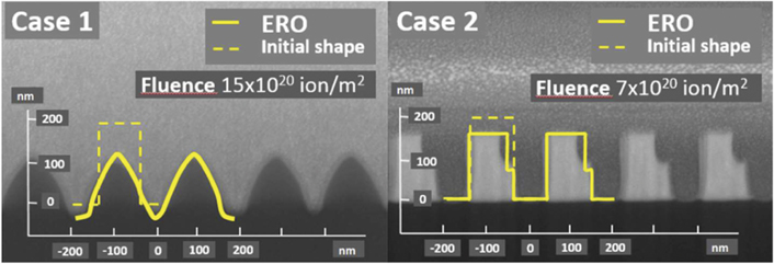
Figure 2. SEM images comparing Si (case 1) and Ta (case 2) surface structures after exposure to an Ar ion beam together with the surface structure modelled by ERO 2.0 indicated as yellow lines. Reproduced with permission from [34]. © 2020 Deutsche Physikalische Gesellschaft.
Download figure:
Standard image High-resolution imageThe comparison clearly shows that the ERO 2.0 model can reproduce the changes in the surface structure which were observed in the experiments. The differences in the resulting surface structure between case 1 and 2 is mostly related to the different incident angle of the Ar ions: the incident angle for case 1 was parallel to the surface normal, while it was at 45° for case 2. The resulting edges on one side of the cylinders is created because the lower part of the cylindrical structures is not reached by the Ar ions (shadowing effect). The different shading of the structures in the SEM images is caused by the different materials [Si substrate (both cases) with Si structures (case 1) or Ta structures (case 2)].
Another example of the influence of the surface structure on erosion yields is shown in figures 3 and 4, where the surface structure found on Beryllium (Be) samples after exposure to D plasmas at the linear plasma generator PISCES-B [36] is implemented in ERO2.0 [34].

Figure 3. Needle-like surface structure (schematic) found on Be samples [36] with exemplary trajectories (red arrows) of sputtered particles (red dots).
Download figure:
Standard image High-resolution image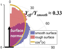
Figure 4. Angular dependence of the erosion yield for rough (needle structure, red) and smooth surface (blue) modelled with ERO2.0 (purple area: overlapping of both red and blue areas). Reproduced with permission from [34]. © 2020 Deutsche Physikalische Gesellschaft.
Download figure:
Standard image High-resolution imageFigure 3 shows a schematic 2D drawing of the needle structure that was found on the Be samples after exposure to the plasma [36]. These experiments with Be samples were performed at PISCES-B, UCSD, due to its unique Be handling capabilities in collaboration between WP PFC and UCSD. The needle-like structure was implemented with identical shape and scale in the ERO2.0 model. The resulting angular distribution of the eroded particles is shown in figure 4 (reproduced with permission from [34]). The figure shows the normalized erosion yield depending on the angle at which the particles are leaving the surface. For the smooth surface, most of the eroded particles are leaving the surface at an angle between 0° and 60° relative to the surface normal, with a maximum at around 45°. For the needle-like structure (rough surface), the angles are more concentrated between 0° and 45° (cos2(x) distribution). Particles leaving the surface at angles higher than this get easily re-deposited on the neighbouring needle structure (as schematically shown in figure 3). Only particles eroded at the top of a needle structure can leave the surface at higher angles without being immediately redeposited. This increased redeposition due to the needle-like structure also results in a decreased effective erosion yield (one third of the effective erosion yield on a smooth surface). Please note that this reduction in the erosion yield is not directly visible in figure 4, as the data is normalized (the same number of eroded particles is shown in both cases) and the coloured areas are not directly comparable on this type of plot.
The findings of these models are not only valid for artificial model structures like nm-scale cylinders or needles, but also for general rough surfaces [30]. The codes have been already applied to assess the temporal surface roughness evolution under linear plasma exposure and perpendicular impact angle, in order to study its impact on the erosion and deposition balance for fusion-relevant materials like W, Be and steel [32, 33, 37]. This will give valuable input for ITER and DEMO predictions, since their divertor surfaces will not be polished.
3D modelling utilising the ERO2.0 code without the surface roughness module has already been applied to benchmark JET (Be, W) [38–40] and WEST (W) [41, 42] experiments as well as to predict the Be migration in ITER [12, 43]. A variety of 2D plasma background solutions from SOLEDGE-EIRENE [44, 45], EDGE2D-EIRENE [46], and SOLPS-ITER [47, 48] were used in the different tokamak cases. The first conclusions from these applications regarding ITER predictions are that the erosion of Be could be higher than previously assumed in certain areas (upper first wall panels) [12]. However, wider parameter studies are required to reduce uncertainties correlated to certain parameters such as the far-scrape-off-layer (SOL) conditions [49]. Additionally, the inclusion of parameters like the surface roughness presented in this section, might change the results of the ITER predictions [12]. If these first results are confirmed though, changes to the first wall design like a replacement of certain Be first wall panels by W at a later stage could be considered [50].
2.3. Qualification of ITER-like monoblocks
In addition to investigating individual effects and topics in the field of PWIs, WP PFC also contributes to the qualification of already existing components and designs, like the reference design concept for the PFCs of the ITER divertor. The reference design consists of W MBs with copper alloy cooling tubes [51]. These elements, either as a mock-up construction for the use in facilities like MAGNUM-PSI [52], or as complete divertor elements in WEST [53], are qualified regarding cracking, melting and other types of damages under variations of plasma and/or heat loads.
Tests of ITER-like MBs at elevated temperature were performed in high fluence experiments in MAGNUM-PSI [52, 54]. The MBs were exposed to the plasma under ITER like divertor conditions with respect to Te, ne, and at sample temperatures of up to 1580 °C. The D fluence reached record values of 1031 D m−2, comparable to one year of ITER divertor operation. A picture of the W MBs during exposure at MAGNUM-PSI is shown in figure 5 (reproduced with permission from [52]-figure 1). The target used in this study is a mock-up consisting of 7 MBs attached to a cooling tube. The plasma seemingly missing the target in figure 5 is only a minor fraction of the outer parts of the plasma profile: the plasma profile of MAGNUM-PSI has a Gaussian shape with a typical full-width at half maximum of 11–14 mm, while the front facing area of a single MB is 21 × 12 mm [52]. Therefore, with the plasma centred at the MB, most of the plasma profile is hitting the target.
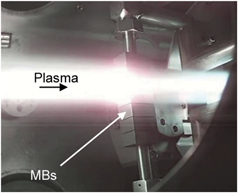
Figure 5. ITER-like MB exposure to D plasma at MAGNUM-PSI. Reproduced from [52]. © Dutch Institute for Fundamental Energy Research.
Download figure:
Standard image High-resolution imageThe results of the exposures showed no visible damage to the samples and extremely low fuel retention, related to the high sample temperature. Re-crystallisation of W occurred in the high fluence experiments in D at the theoretically predicted material temperatures. These results give confidence in the lifetime predictions of the ITER divertor. However, follow-up experiments on the impact of pulsed heat loads by laser (ELM simulations) [55] have shown a significantly lower resistance of the samples for fatigue cracking, which suggests extensive cracking at the strikepoint locations in ITER when ELMs are present, both for recrystallized and non-recrystallized W.
Parallel to these studies, ELM simulations by combined laser and plasma exposition and e-beam impact were carried out for high cycle numbers of up to 106 ELM-like pulses [56, 57], to study the response of W to repetitive transient heat loads. In figures 6(a) and (b), results from Gago et al (reproduced with permission from [56]-figure 2) show the surface structure after 106 ELM-like pulses with and without plasma exposure. During the exposure, the samples (forged W with transversal grain elongation) reached a base temperature of 700 °C–900 °C, increasing by 300 °C during the thermal shock events (depending on the power density, here: 0.2 GW m−2, with a pulse frequency of 10 Hz and a pulse duration of 0.5 ms).
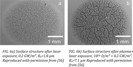
Figure 6. (a) Surface structure after laser exposure, 0.2 GW m−2, Ra = 1.8 μm. (b) Surface structure after plasma + laser exposure, 1026 D m−2 + 0.2 GW m−2, Ra = 7.1 μm. Reproduced with permission from [56].
Download figure:
Standard image High-resolution imageA reference experiment without laser pulses shows that plasma exposure alone does not lead to any visual change in the surface structure of the sample [57]. On the other hand, the laser pulses without plasma exposure cause an increase in the roughness (Ra) of the sample surface and small cracks on the surface (figure 6(a)). While also the increase of the laser power density leads to stronger cracking and melting of the material [56, 58], the damage to the surface also increases significantly for a combined plasma and laser exposure (figure 6(b)) at the same laser power density of 0.2 GW m−2. This synergistic effect is attributed to the D trapped in the surface layer of the sample, which reduces the damage threshold of the material. Both this study and the experiments at MAGNUM-PSI confirm the significant impact of ELM-like heat loads on cracking and therefore also on the overall lifetime expectancy of the ITER divertor.
Additional emphasis was put on the study of MB castellation, shaping and height to mimic the specifications in ITER (+/− 0.3 mm). ITER MBs with different shaping were installed in WEST for this purpose [11, 59, 60]. The local damage of optical hot spots, which are the optical projection of toroidal gaps on the leading edges of neighbouring MBs [61], has been observed. These optical hotspots are also predicted for ITER and no additional protection or shadowing of these locations is currently foreseen. The question of the impact of edge melting on ITER operation still needs to be further investigated; but it is a complex issue which might only be fully solved with the beginning of ITER exploitation [61]. On the side of modelling, dedicated particle-in-cell (PIC) modelling was applied and identified the particle and power fluxes [62]. The same modelling code was used for ITER predictions about the particle and power fluxes in the castellation and role of MB shaping.
All three studies contribute to the determination of the operational window for the W MBs in the ITER divertor regarding heat loads, transients, and surface temperature conditions [63]. While the edge melting requires additional studies to clarify the impact on ITER operation [61], the fatigue cracking of W surfaces to ELM-like heat loads is confirmed by multiple studies [55–57]. This issue could be mitigated either by the suppression of ELMs (ELM-free scenario [28]), or by the development of advanced materials that have a higher damage threshold under these conditions. For this purpose, studies with plasma and high heat flux exposure on advanced W materials started in WP PFC in 2019. The surface damage evolution was compared to previous studies on the ITER-grade reference W regarding synergistic effects with combined plasma and heat loads. As an example, micro-structured W [64] (parallel W fibres with 150 μm diameter and no interface material, oriented vertical to the sample surface) has proven to withstand the combined plasma and laser loads without significant damage. New, advanced materials always require the full investigation of other important parameters like fuel retention and erosion. The micro-structured W has not shown significant drawbacks in these areas so far [65]. Of course, a completely qualified and proven divertor design with such materials is currently not available for ITER. Nonetheless, advanced materials could be a possible solution if no method to avoid the ELM-induced damages is viable for ITER, or if other effects not related to ELMs (for example first wall heat loads due to blobs in DEMO [66]) cause similar issues.
2.4. Fuel retention
The fuel retention in wall materials, as an important safety and operational issue in ITER and DEMO, is also one of the main research areas of WP PFC. Dedicated experiments were carried out to quantify the fuel retention in W with combined D and impurity seeding exposure in laboratory and linear plasma devices. The latest studies were focussed on nitrogen (N) as a potential ITER seeding species. Here, a strong enhancement of the D retention has been identified in experiments at PSI-2 [67], even at high sample temperatures of up to 800 K during plasma exposure. This in contrast to exposures with pure D or D + He plasmas, where the D retention is reduced significantly with higher temperatures above 500 K [67, 68]. At higher temperatures, diffusion of D is increased and D in low-energy trapping sites is desorbed during the plasma exposure, resulting in an overall reduced D retention in the samples. For the case of D + N exposure, it is assumed that the formation of a WN layer on the surface acts as a permeation barrier [67, 69], which reduces the desorption of D during the plasma exposure. Consequently, the D retention with D + N exposure is 2 orders of magnitude bigger than the D retention with pure D exposure, and more than 3 orders of magnitude bigger than the D retention with D + He exposure [67].
As a next step, the influence of N impurities at temperatures above 800 K will be investigated. Previous experiments with pure D or D + He plasmas and sample temperatures of 1100 K show that the resulting D retention is reduced below the detection limit of the thermal desorption spectroscopy (TDS) system (1018 D m−2) [68]. It is assumed that the D retention will decrease also for D + N exposure at temperatures above 800 K, since the WN layer dissolves at temperatures above 800 K [70]. Nevertheless, the clear increase in D retention for sample temperatures of up to 800 K alone could have negative consequences on the fuel retention in ITER, which need to be considered when applying N seeding at ITER. However, the influence of N seeding on the tritium removal cycles at ITER is not quantified yet and must be investigated in future studies. Also, follow-up experiments are underway to study the retention with the help of model systems in the form of co-deposits consisting of W and/or Be plus a variety of gases like D, He, N, or neon (Ne).
Another area which was investigated is the fuel retention in combination with neutron damage proxies in view of DEMO conditions. Self-damaging by energetic W ions was applied to simulate neutron-induced defects in W and mimic the impact of fusion neutrons. Markelj et al [71] found that the retention also depends on the sequence of damage creation and plasma exposure. As an example, figure 7 (reproduced with permission from [71]-figure 9) shows the results for the D retention in samples with sequential damaging and plasma exposure (pink, 'sequent. W–D') compared to the D retention in samples with simultaneous damaging and plasma exposure (blue, 'simult. W/D–D'). The results are shown as a function of the sample temperature during W ion damage (x-axis). For the sequential case, the D plasma exposure was performed afterwards at 450 K sample temperature. For the simultaneous case, the samples have been additionally exposed to D plasma in the same way at 450 K after the simultaneous damaging + plasma exposure. This was done to populate the created defects and make the conditions in terms of D loading comparable to the sequential case. The D retention was measured with TDS and nuclear reaction analysis (NRA). NRA was performed at 2 different locations on the sample: 'NRA max' is the location of maximum proton signal during NRA measurements, while 'NRA centre' is the centre of the ion damage area.
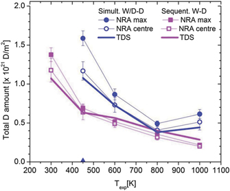
Figure 7. Total D amount for sequential W–D exposure and simultaneous W/D–D exposure as obtained by TDS (thermal desorption spectroscopy, line) and NRA (nuclear reaction analysis, symbols) with two different locations for NRA measurements: 'NRA max' = location of maximum proton signal during NRA measurements, 'NRA centre' = centre of the ion damage area. Reproduced courtesy of IAEA. Figure from [71]. Copyright (2019) IAEA.
Download figure:
Standard image High-resolution imageThe results of the different measurement techniques and locations are in good agreement, except for the 'NRA max' measurement at 450 K, where the maximum D retention was found outside of the centre of the W ion damaging zone.
In general, the results show that the D retention is higher for the case of simultaneous damaging + plasma exposure, compared to the sequential case. The plasma exposure during the W ion damaging leads to a stabilisation of the displacement damages due to the implanted D in the surface; resulting in more trapping sites for the D in the sample. The D retention is in both cases reduced with increasing sample temperature during W ion damaging, which is related to the annealing of the created damages at higher temperatures [71]. At a sample temperature of 800 K, the damage stabilisation effect has almost no influence anymore, as the D concentration in the implantation zone is decreased due to increased D diffusion. Interestingly, at 1000 K sample temperature, there is again an increase in the D retention for the simultaneous case. It is speculated that this is caused by a new type of defect being created in the sample, which can be stabilised by D even at such high temperatures [71]. Additional experiments are needed to clarify the effects at high temperatures. If the stabilisation of ion damaging effects and the resulting increased D retention is indeed occurring also at temperatures of 1000 K and more, this could also have negative consequences for the fuel retention and fuel removal at ITER.
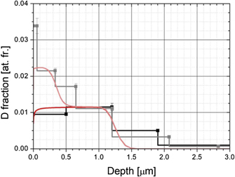
Additionally, detailed modelling was applied to simulate the observed enhancement of retention in the near surface. The work from Pecovnik et al [72] shows that the damage stabilisation effect and the resulting increased fuel retention can be reproduced with a rate-equation model using the MHIMS code [73] (figure 8, reproduced with permission from [72]).
Figure 8. D retention depth profile (D atomic fraction vs depth) with NRA measurements (black) and by modelling (red) for sequential (opaque) and simultaneous (transparent) ion damaging + plasma exposure at 450 K sample temperature. Reproduced with permission from [72].
Download figure:
Standard image High-resolution image
Both the results from the model and from the NRA measurements show the increased D retention in the first 500 nm below the surface for the case of simultaneous damaging and plasma exposure at 450 K sample temperature. This depth corresponds to the depth where D can reach high concentrations by implantation and diffusion under the exposure conditions present [71]. The atomic fraction (fraction of D atoms in relation to total number of atoms at a certain depth) plotted in figure 8 increases from 1% for the sequential case to 2% for the simultaneous case. This significant increase indicates that additional trapping sites are present in the first 500 nm for the simultaneous case. Therefore, it can be concluded that the high D concentration during exposure in this area leads to a stabilisation of the displacement damages, which results in a higher D retention in this area.
The impact of neutron damage is one of the main topics that require a lot of new and follow-up studies in the future, due to multiple reasons: firstly, neutron damage can potentially have an impact on all areas of PFC research (fuel retention, material damage thresholds, erosion). Secondly, experiments are difficult due to the specifics of fusion neutrons, which are hard to reproduce or to mimic by proxies, and due to the safety issues related to the handling of neutron activated materials. Within the EUROfusion consortium, new facilities are designed and constructed for the operation with activated material samples, like the JULE-PSI linear plasma facility [74]. However, the results from [71, 72] presented here are already showing that synergistic effects must be always taken into account, especially when interpreting results from experiments where such simultaneous damaging and plasma exposure of the sample is not possible.
Finally, WP PFC also investigates new methods for PWI diagnostics. The goal is not only to improve the diagnostics required for the studies within WP WPC, but also to develop methods for later use in ITER and other facilities. One example is the quantification of the T and D retention in the first wall material of fusion devices with in-situ methods (without removing samples from the facility). A dedicated task utilising laser-induced breakdown spectroscopy (LIBS) in PSI-2 [75] and MAGNUM-PSI [76] as well as LIBS/laser-induced ablation with quadrupole mass spectroscopy (LIA-QMS) in laboratory arrangements was executed successfully for this purpose [77–79]. The set of laser-based experiments demonstrated the capability to resolve hydrogen isotope as well as quantify the fuel retention in different types of ITER-like co-deposits, containing Be and W as well as other impurities found in JET samples.
3. Summary and outlook
The paper gives an overview about the recent key results of research within WP PFC regarding He–W interaction, surface modifications and erosion, qualification of ITER-like W MBs, and fuel retention in W under the influence of plasma impurities and neutron irradiation. As described in the introduction of the paper, the Work Package covers a very wide range of topics, therefore the paper can only focus on some of the recent highlights.
In the area of He–W interaction, experiments with W samples exposed to He plasmas in the divertor region of the ASDEX-Upgrade and WEST tokamaks showed that the W fuzz creation or erosion depends strongly on the local plasma and surface temperature conditions around the outer strike line. Depending on the position, new W fuzz was formed at ASDEX-Upgrade during the tokamak exposure (above strike line), or pre-existing W fuzz was completely eroded during the tokamak exposure (at the strike line). At the same time, He plasmas in the WEST tokamak have not created any W fuzz on the divertor sample surfaces, although the conditions for W fuzz growth have been reached. This shows that other parameters, which might have been not taken into account previously, could suppress the growth of W fuzz. In this case, further studies are required to clearly identify any parameters that suppress the W fuzz growth. In general, it is currently estimated that W fuzz growth will not negatively affect the lifetime of the ITER divertor. But if important parameters like the erosion by ELMs are changed (for example with an ELM-free scenario for ITER), the resulting lifetime estimations might change. Here, the resulting data of the presented experiments can be used to benchmark models relevant for the lifetime estimation of the ITER divertor.
Studies on the surface structure modifications and erosion in lab-scale experiments have shown how the W fuzz or other microstructures on the sample can influence the effective W erosion yields by increased redeposition within the surface structure. These influences have been successfully implemented in erosion models. The combination of these laboratory and tokamak experiments is used to benchmark also global migration codes with novel surface roughness modules (e.g. in ERO2.0), and to predict global material erosion and migration in ITER. As an example, current predictions of the Be erosion and transport (without the implementation of surface roughness effects) predict a negative impact on the first wall lifetime due to enhanced erosion in certain areas of the first wall (upper first wall panels). Including the surface roughness effects and other improvements might change the results and therefore the predictions for ITER.
For the qualification of ITER-like MBs under plasma load, multiple aspects have been investigated: in the linear plasma facility MAGNUM-PSI, record values for the D fluence of 1031 D m−2 have been reached under ITER-like divertor conditions at low electron temperature. The MBs proved to withstand this high fluence with no visible surface damages of the W MBs and a very low fuel retention at 1580 °C surface temperature. However, follow-up experiments with ELM-like laser-induced heat loads show a significantly lower damage threshold with respect to cracking. The same was observed in experiments with simultaneous plasma and heat loading (ELM-simulation) at PSI-2 and JUDITH. The results revealed that the damage thresholds of the material are reduced due to synergistic effects, as the D implanted in the surface amplifies the damage and cracking caused by the pulsed laser heat loads. These results show that during ITER operations, ELMs need to be mitigated. Advanced materials, that have a higher damage threshold with the synergistic effects taken into account, are being designed and qualified as alternative solutions. First concepts, such as micro-structured W, show a much higher damage threshold under ELM-like heat loads, and are also comparable with respect to other parameters such as erosion and fuel retention. Therefore, such advanced materials could be a backup strategy, if other effects cause similar cracking issues in future devices, even with ELM-free scenarios. Additionally, damages due to optical hotspots have been observed for the ITER-like MBs in the divertor at WEST under D and He plasmas. Particle and power flux to these hotspots was modelled by PIC simulations and applied for ITER predictions about castellation and shaping. However, to fully quantify the consequences of edge melting on ITER operation, more modelling efforts are necessary, and ultimately also experiments at ITER in the future.
Finally, in the area of fuel retention, it was identified that N as a plasma impurity increases the fuel retention of W PFCs. The results indicate that there are negative consequences for the fuel retention and tritium removal in ITER if N seeding is foreseen. Additionally, experiments with simultaneous plasma exposure and W ion damaging, have revealed that the displacement damages caused by neutrons (or W ions as a proxy) can be stabilized by the implanted D from the plasma, also leading to an increase in fuel retention. This damage stabilisation effect was also successfully implemented in fuel retention modelling.
Overall, the results support the PFC qualification for ITER and DEMO, and contribute to the understanding of PSI physics, as well as the progress of PSI modelling.
Acknowledgments
This work has been carried out within the framework of the EUROfusion Consortium and has received funding from the Euratom Research and Training Programme 2014–2018 and 2019–2020 under Grant agreement No. 633053. The views and opinions expressed herein do not necessarily reflect those of the European Commission.