
Abstract
Optical generators of strong magnetic fields based on the laser-driven-coil target concept are considered to be useful tools for studies of magnetized plasmas in particular, for the study of implosion of magnetized fusion targets in inertial fusion research and astrophysical applications. This paper presents the results of the research directed at an investigation of the plasma properties in a laser-induced magnetic field. In the experiment carried out on the kilojoule PALS laser facility, a generator of the magnetic field was a disc-coil (DC) target composed of a Cu disk coupled to a single-turn coil irradiated by a 1ω laser beam with an energy of 500 J. The attention was focused on examining the influence of the magnetic field on properties of the hot electron (HE) flux emitted from the front surface of the irradiated target. The three-frame complex interferometry and four-frame x-ray camera combined with the measurements of the HE population and energy using a multi-channel magnetic electron spectrometer and 2D-resolved imaging of the induced Cu Kα line emission were applied to characterize the ablative plasma and the generated particles. Based on the measured angular distributions of the electron energy spectra, 3D simulations have been performed to visualize the effect of the magnetic field on the HE flux and to provide information on space-time distribution of the electron and current density both without and with the presence of an axial magnetic field. The obtained results confirmed the possibility of generating magnetic fields above 5 T using the proposed DC target design as well as the significant impact of these fields on properties of the ablative plasma and the HE emission.
Export citation and abstract BibTeX RIS

Original content from this work may be used under the terms of the Creative Commons Attribution 4.0 license. Any further distribution of this work must maintain attribution to the author(s) and the title of the work, journal citation and DOI.
1. Introduction
In inertial confinement fusion (ICF) [1–3], a capsule consisting of cryogenic deuterium and tritium and filled with DT gas is rapidly compressed to high temperatures and densities sufficient for nuclear fusion reactions. Provided the α particles generated by the D-T reactions are confined and deposit their energy in the compressed core, the capsule ignites and the energy released via the fusion burn can exceed the energy driving the implosion, i.e., the fusion gain exceeds unity. The requirements for hot-spot ignition, particularly the ion temperature, impose a lower limit on the shell implosion velocity. It must be large enough so that the shell-imparted work overcomes the core's thermal losses. Therefore, the minimum imposed by thermal losses directly limits the gain achievable through ignition. In the concept of magnetized ICF [4], additional thermal insulation of the hot spot is achieved by applying a strong magnetic field to an otherwise conventional ICF fuel assembly [5, 6]. The first experiments were performed on the OMEGA Laser at the Laboratory for Laser Energetics and they constitute the first experimental evidence of a fusion performance enhancement through magnetization of an ICF hot spot [6]. In particular, a neutron yield enhancement of 30% and an ion temperature increase of 15% were observed. It shows enough, that magnetization is a promising strategy to increase ICF yields, as the presence of a B-field strongly modifies fundamental properties of the compressed plasmas. The key issue is heat transport, which regulates the laser energy transfer from the corona to the ablation front and becomes anisotropic in the presence of a strong field (kT) [7, 8]. Furthermore, seed B-fields can be amplified by ∼500 times to strengths up to B > 10 kT through compression of the plasma [6]. In contrast to the conventional ICF, the magnetic implosion may be less prone to hydrodynamic instabilities [9, 10] which is crucial for achieving fusion ignition.
The most promising magnetic field geometry for the implementation of the ICF magnetic implosion is the axial magnetic field Z-pinch used in the Magnetized Liner Inertial Fusion experiments [11, 12]. These experiments confirmed the expected effect of plasma magnetization in terms of obtaining a more stable (adiabatic) compression leading to an increase in neutron yield enhancement and an ion temperature.
Large opportunities in the research related to the implementation of inertial fusion by magnetic implosion are offered by optical generators of strong magnetic fields based on laser-driven-coil targets (LDCT) [13–15]. Such targets are predicted to implement the idea of the ICF magnetic implosion on the Laser Mégajoule (LMJ) laser system in Bordeaux, their role bears upon pre-magnetizing a cylindrical target with fuel [16]. The assessments presented in that paper show that for laser intensities of around 1015 W cm−2 available on the LMJ, the conditions for extreme magnetization can be reached using a relatively low seed B-field. The initial field at the 5 Tesla level can be compressed to more than 10 kT which is sufficient to effectively influence the electron and ion heat transport to obtain the temperature and fuel density values required for the fusion ignition.
The significant influence of the quasi-static magnetic field on the properties and possible use of plasma as a secondary source was experimentally and theoretically proven in relation to the pre-plasma produced by a sub-nanosecond laser [17, 18], where the femtosecond laser pulse interacts with the pre-plasma on the critical surface. It has been shown that such controlled parameters of ablative plasma can find application in various fields of applications, such as generation of THz radiation [19], production of fast ions for implantation [20] and also help to elucidate nonlinear laser-plasma interactions.
This paper presents preliminary results of experiments carried out at the Prague Asterix Laser System (PALS) iodine laser facility [21] concerning the production of magnetized plasma streams with the use of disc-coil (DC) targets (DCTs). The aim of this research is to understand the influence of the magnetic field on parameters of the ablative plasmain particular, on the generation of hot electrons (HEs) and ions responsible for the transport of the laser radiation energy to the shock wave. These phenomena are important for the implementation of the ICF, in accordance with the shock ignition concept, the idea of magnetic implosion and astrophysical applications.
The subject of this research is the magnetized plasma generated by the interaction of the 1ω PALS laser beam with a target consisting of a copper foil disc coupled to a coil (figure 1). Plasma expands in the axial magnetic field generated by the current flowing in the DC circuit. To investigate the influence of the magnetic field on the parameters of the expanded plasma, the three-frame complex interferometry [22–24] and four-frame x-ray camera [25] were implemented in combination with measurements of the HE energy distributions using the multi-channel magnetic spectrometer [26] and 2D imaging of the Cu Kα line emission [27].

Figure 1. Experimental setup: (a) scheme of diagnostics location in the experimental chamber, (b) DCT with the SC for creation of the magnetized plasma (DT-STCM), (c) DCT-SC for measuring magnetic field in the coil via Faraday effect in the TGG crystal.
Download figure:
Standard image High-resolution imageThe paper is structured as follows. In section 2 the experimental set-up is presented including description of the target construction and diagnostics used. Section 3 presents results of measurements and their discussion. In section 4, results of 3D numerical simulations demonstrating influence of the axial magnetic field on the HE emission are presented. The general conclusions resulting from the performed studies are presented in section 5.
2. Experimental setup
Investigation of the axial magnetic field effect on the expansion of the ablative plasma created at the Cu foil accompanied by the emission of electrons was carried out by means of the experimental set-up presented in figure 1(a). To simultaneously generate the plasma and the axial magnetic field, the targets consisted of Cu discs coupled to a single-turn coil(SC). The detailed design of these targets operating on the principle of LDC targets is shown in figure 1(b). The origin of the magnetic field generated by the coil is the current flowing through the DC circuit, which results from the disc uncompensated charge due to the escape of a portion of the laser-produced HEs away from the disc.
The targets were irradiated by a random-phase-plate-smoothed beam of the PALS iodine laser with an energy of about 500 J and duration 300 ps focused to the minimum focal spot radius (about 50 μm), which resulted in an intensity on the target above 1016 W cm−2.
To assess the current and magnetic field distribution in the coil, measurements of the Faraday effect were carried out using the terbium gallium garnet (TGG) crystal placed at an appropriate distance from the coil, as shown in figure 1(c). The coil was located perpendicularly to the disc in a special holder, which protected the TGG crystal against x-rays. To determine the current and the magnetic field in the coil, the quantitative analysis of the measurements of the Faraday rotation angle in TGG crystal was used [24].
The complex investigation of the influence of the axial magnetic field on the parameters of the ablative plasma benefitted from a versatile diagnostic system consisting of:
- Three-frame complex interferometry measuring the space-time electron density and the SMF distributions in the expanded plasma [22, 23],
- Four-frame x-ray pinhole camera visualizing the expansion plasma process in the range of the soft x-ray radiation [25],
- 2D imaging of the Cu Kα line emission [27] providing information on parameters of the HE emission, namely the total number of photons generated as a result of the interaction of HEs with a copper disc, the energy and laser-to-HE conversion efficiency for HEs deposited in the central hot spot of the targets, the fraction of the HEs deposited outside the central hot spot and
- the multi-channel electron magnetic spectrometer [26] measuring the angular characteristics of the HEs emitted outside the Cu discs, i.e. the number of HEs emitted at different angles vs the target normal and angular distributions of their energy and temperature.
The location of all diagnostics in the interaction chamber is schematically shown in figure 1(a).
In order to verify the origin of effects induced by the coil generated magnetic fields on the plasma, all diagnostic data were collected alternately by irradiating the bare Cu discs, as reference interaction shots, and those connected with the coils. Via the comparison with the reference measurements performed at similar experimental conditions, the field affected phenomena could reliably be identified.
3. Results of measurements
Exemplary results of measurements obtained by all diagnostics are presented in figure 2. The results shown on the left illustrate the influence of the generated magnetic field on various characteristics of the ablative plasma produced from the Cu DCT irradiated by the 1ω laser beam with an energy of about 500 J. On the right side, the analogous results obtained from the Cu disc without the coil are shown. The effect of the magnetic field generated by the coil on the plasma expansion is clearly visible in soft x-ray images from the four-frame pinhole camera, figure 2(b). In particular, in the presence of the magnetic field, the plasma stream, even in the late phase of the expansion of about 10 ns after the laser-plasma interaction, is strongly collimated, whereas in the absence of a field, i.e. at the beginning of the interaction, e.g. 370 ps before the maximum intensity of the laser, the plasma is still expanding into the cone by default, as demonstrated by the complex interferograms recorded after the end of the laser pulse in figure 2(a). The breaking point in radial plasma expansion caused by the axial magnetic field produced by the coil is visible on the interferogram for t = −17 ps, as figure 3 shows. The elucidation of this phenomenon requires a quantitative analysis, which will be presented later. The strong influence of the axial magnetic field on the HE emission results also from the 2D imaging of the Cu Kα emission (figure 2(c)) and the measurements of the angular energy distribution of the HE spectra recorded by the multi-channel electron magnetic spectrometer (figure 2(d)). In the case of the Kα (figure 2(c)), the presence of the axial magnetic field leads to the enhanced laser energy deposition and HE production in the Cu disc target. The comparison of the electron energy spectra (figure 2(d)) also shows the magnetic field-induced increase in the energy of HEs emitted in the backward direction along the target normal.
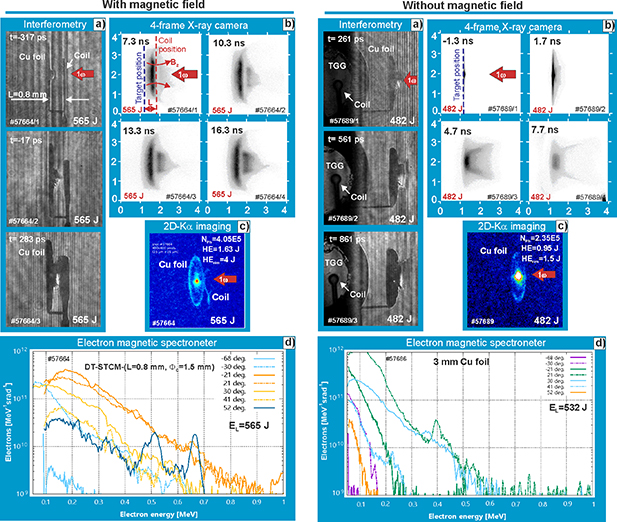
Figure 2. Sample results of measurements obtained using: (a) complex interferometry, (b) 4-frame x-ray camera, (c) 2D imaging of Cu Ka emission, and (d) multi-channel electron spectrometer, using the DCT (with B-field, on the left) or the disk-only target (without B-field, on the right).
Download figure:
Standard image High-resolution image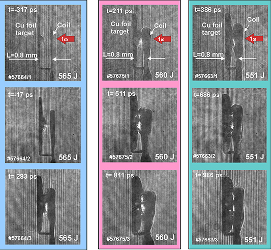
Figure 3. The sequences of complex interferograms illustrating the plasma expansion in axial magnetic field recorded at different time delays. The DCT producing the magnetic field was irradiated by the 1ω laser beam with the energy of about 500 J.
Download figure:
Standard image High-resolution imageMore detailed information on the influence of the magnetic field on the plasma expansion and electron emission will be presented in further sections where the results obtained from individual diagnostics will be discussed.
3.1. Complex interferometry results
3.1.1. Interferometric investigations with use DT-STCM targets.
To obtain information about space-time distribution of spontaneous magnetic field (SMF) and electron density in expanding plasma stream, the three-frame polaro-interferometer operating in the complex interferometry option has been implemented [22, 23]. Here we report the research performed with DCT with the SC for creation of the magnet (DT-STCM) targets defined in figure 1(b). The interferometric system used the radiation of the Ti:Sa laser with a pulse length of about 40 fs delivered via an optical delay line, which allowed to register 3-frame sequences of complex interferograms with an adjustable interval between individual records. Typically, three interferograms with the temporal interval of 300 ps between the frames were registered. The covered range could be adjusted from t = −500 ps up to about t = 1000 ps, as defined by the first frame delay vs the main laser beam maximum. Three frame sequences of complex interferograms illustrating the plasma expansion in axial magnetic field generated by the DT-STCM target are presented in figure 3. For t < 283 ps, the presented interferograms show the visible Faraday effect in the lower half of interferograms only. This confirms the axial symmetry of the SMF in the formed plasma and no influence of the Couton–Mouton effect on the polarization state of the diagnostic beam caused by the coil induced axial magnetic field.
In the later phases of the expansion, but still during the laser-plasma interaction, starting from t > 283 ps, the influence of the Cotton–Mouton effect is clearly visible, as evidenced by the luminous spots in the top half of interferograms. A gradual limitation of the field of view due to the expansion of the coil material under the current flows and the coil irradiation with x-rays emitted from the disc target represents an additional difficulty in the quantitative interpretation of interferograms. With respect to this, only the interferogram for t = −17 ps is readable enough to obtain quantitative information on the SMF and electron density distributions.
Distributions of the SMF, electron density and current density which demonstrate the influence of the coil-created axial magnetic field on the expanding plasma at t = −17 ps are presented in figure 4(a), while figure 4(b) shows the expansion of the plasma produced from the Cu disc without the coil. In contrast with the soft x-ray images from the pinhole camera, figure 2(b), which show the effect of the magnetic field on the thermal plasma, the complex interferometry reveals the influence of the axial magnetic field on the ablative plasma during the laser pulse period when the HEs are emitted. The comparison of the distributions presented in figures 4(a) and (b) clearly demonstrates that the axial magnetic field gives rise to changes in the distribution of the electron density and to the increased amplitudes of the SMF and the current density, which consequently cause the increase in total current associated with the motion of electrons both from and to the target.

Figure 4. Distributions of electron density, SMF, direct current density and total current obtained in the case of: (a) presence and (b) absence of the magnetic field.
Download figure:
Standard image High-resolution image3.1.2. Interferometric investigations with use DCT-SC targets.
The measurements of the current and magnetic field in the coil were carried out using the targets DCT-SC (see figure 1(c)). To measure the Faraday effect in the TGG crystal, the coil was positioned perpendicularly to the Cu disc in a special holder which protects the TGG crystal against x-rays emitted by the plasma (see figure 5(a)). The sequence of complex interferograms illustrating the Faraday effect in the TGG crystal and the ablative plasma at laser irradiated Cu foil is shown in figure 5(a). To determine the current and the magnetic field in the coil, the quantitative analysis of the measurements of the Faraday rotation angle in TGG crystal described in paper [24] was applied. As results from the sequence of recorded interferograms, figure 5(a), the signal in the TGG crystal darkens, therefore there is an ambiguity connected with two different rotation angles (ϕ1 or ϕ2) for the same signal intensity, see the diagram on figure 5(b). These alternate angles correspond to two different magnetic fields. The distribution of the magnetic field in the coil calculated on the basis of the second variant (ϕ2 = 2β–θ), which seem appropriate taking into account the diagram of figure 5(b), are shown in figure 5(c).
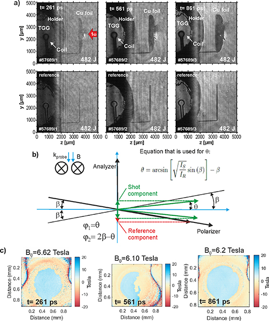
Figure 5. Current and magnetic field measurement using DCT-SC targets. (a) The sequence of the optical probing experimental images illustrating the Faraday effect in the TGG crystal along the coil axis and the ablative plasma at the Cu plate by complex interferometry. The bottom images are the reference images without pump laser for each of the top images (b) the diagram illustrating ambiguity connected with two possible different rotation angles due to the same signal intensity, and (c) distribution of the axial magnetic field in the coil derived from measurements of the Faraday effect in TGG crystal in different times of plasma expansion.
Download figure:
Standard image High-resolution imageThe summary of the results obtained at two different energy levels of the main laser and various delays of the diagnostic laser vs the maximum of the iodine laser intensity is presented in figure 6. These results confirm that the DCT used in the present research, figure 1(c), allow to obtain a magnetic field with an induction of about 5–7 Tesla in the center of a SC.
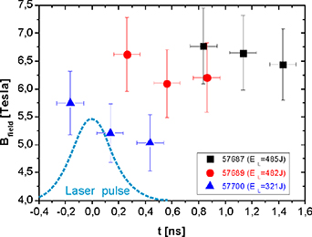
Figure 6. The measured value of the magnetic field generated in the center of the coil when irradiating the DCT-SC targets at two different energy levels of the main laser and for different times of the plasma expansion related to the maximum intensity of the pump laser (indicated by the dashed blue curve).
Download figure:
Standard image High-resolution image3.2. 2D imaging of the HE-induced Cu Kα line emission
The 2D x-ray Cu Kα imaging system with the spherically bent crystal of quartz (422) was applied for a characterization of the spatial extent, total population and the efficiency of the laser energy conversion into HEs propagating inside the DC Cu targets. The HEs with energies above the Cu K-edge ionization limit (i.e. above 8979 eV) interact with the relatively cold and dense target material and create holes in the K atomic shells which results in the emission of the Cu Kα photons. The details of the method used are described in the paper [23], here we assume that the 2D-resolved magnified images of the Cu Kα1 emission were observed at the angle of 17.2° vs the irradiated Cu disc surface, recorded onto the FUJI BAS MS imaging plates and scanned using the Amersham Typhoon reader with a pixel size of 25 × 25 μm2. The lateral extent of the HE emission from the central target area corresponding to the laser incidence onto the Cu foil was slightly larger (with the FWHM value of 160 µm) than that of the focused laser beam. This broadening can be explained by a slightly divergent flux of HEs created in the plasma corona above the target surface and/or by the lateral spreading of the HEs along the target surface. The spatially and temporally integrated monoenergetic photon fluxes from the central parts of the discs were correlated with the generated HE dose (0.9–2.2 J) and the conversion efficiency of the laser beam energy into HEs (0.2%–0.4%) using the GEANT4 code [28]. We note that these values were estimated under assumption that a prevailing part of the created HEs propagates inside the target, i.e., they represent lower limits and the real HE populations can be proportionally larger. The scheme of the HE diagnostic and sample 2D images of the integral Kα1 emission from disc targets in the presence and absence of a magnetic field are presented in figure 7.
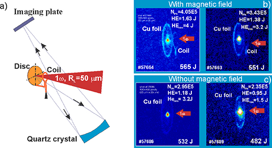
Figure 7. Scheme of the HE diagnostic based on 2D x-ray imaging of the Cu Kα1 emission (a) and a comparison of the emission characteristics observed at the DC and bare Cu disc targets with a diameter of 3 mm at the presence (b) and the absence of the magnetic field (c).
Download figure:
Standard image High-resolution imageThe presence of the magnetic field increases both the emission of HEs and the energy deposited in the target material, which in turn leads to an increase in the conversion of the laser radiation into the HE energy. An overall comparison of the Cu Kα1 emission parameters from targets with DCT-SC and the bare Cu disc foil taking into account the shot-to-shot laser energy variation of the target irradiation is shown in figure 8.

Figure 8. Comparison of the Cu Kα emission parameters measured at single coil targets with parameters found for bare Cu foil discs. They characterize: (a) the number of photons generated from the central spot due to the interaction of HEs with a copper disc, (b) the energy of the HEs deposited in the central hot spot, (c) conversion efficiency of the laser energy into HEs and (d) the total energy of the HEs deposited in and outside the central hot spot.
Download figure:
Standard image High-resolution imageThese graphs indicate that the magnetic field generated by a SC causes an increase: (a) in emission of HEs (as shown by the emission of photons per unit solid angle (figure 8(a)), (b) in the energy of HEs deposited in a Cu disc (figure 8(b)), and in the conversion of the laser radiation into energy of HEs (figure 8(c)). However, as shown in figure 8(d), the energy of HEs deposited outside the central 'hot spot' area is largest in the case of copper foil discs. This is an important experimental fact, as it confirms the expected positive influence of the magnetic field on the emission of HEs. This finding, however, needs to be confirmed in a larger number of shots at similar irradiation conditions of discs-coil and bare-foil discs.
3.3. Measurements using multi-channel magnetic electron spectrometer
The characteristics of HEs emitted from the interaction region outside the target surface were investigated using a multi-channel magnetic electron spectrometer [26] schematically shown in figure 9 where the configuration of individual modules is depicted. The typical measured data processed using the known characteristics of the spectrometer are presented in figure 10.

Figure 9. Multi-channel magnetic electron spectrometer: (a) location of the dipole magnet array in the experiment, (b) the construction of individual magnetic dipole modules and (c) the calibration curve.
Download figure:
Standard image High-resolution image
Figure 10. Typical electron energy spectra measured at different angles of the HE emission vs the normal to the target surface for the case of: (a) Cu discs with a coil and (b) Cu discs without a coil. The discs of 3 mm in diameter were irradiated by the 1ω PALS laser beam with an energy of about 500 J.
Download figure:
Standard image High-resolution imageDifferences in parameters of the electron emission from the ablative plasma caused by the influence of the magnetic field are also evident in angular measurements of the electron energy spectra recorded with the multi-channel magnetic electron spectrometer, presented in figure 10. The differences between the total energy and temperature of the HEs emitted from DT-STCM targets with the coil compared to the HEs emitted from the Cu discs without the coil are clearly visible in the collective distributions shown in figure 11, where the measured data are fitted by Gaussian functions. Results from the comparison of figures 11(a) and (b), the presence of the magnetic field does not significantly affect the number of emitted electrons caused by the laser energy dispersion (which is in line with expectations), but it reveals in a noticeable increase in the HE energy and their temperature observed in the backward directions with respect of the laser beam. Under the presence of the magnetic field generated by a SC, the maximum energies of electrons emitted in the vicinity of the axis may exceed a value of 1 MeV, while their temperature may reach almost 100 keV, what is illustrated by the sequence of figure 11(a). The methodology described in [26] was used here for the quantitative analysis of energy spectra.
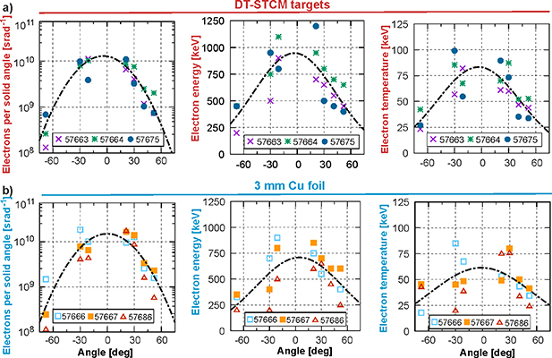
Figure 11. Collective comparison of the electron emission parameters: (i) total number of electrons emitted per unit solid angle, (ii) electron energy and (iii) their temperature, in the case of: (a) Cu DCTs and (b) copper foil discs of 3 mm in diameter. Irradiated by the 1ω PALS laser beam with an energy of about 500 J.
Download figure:
Standard image High-resolution image4. Numerical simulations
Angular measurements of the HE emission using the multi-channel electron spectrometer turned out to be particularly useful diagnostics for investigating the magnetic field influence on the properties of HEs emitted from the plasma generated by DT-STCM. Based on the observed angular distributions of the electron energy spectra in combination with the measurements of the magnetic fields in the coil using the DCT-SC targets, 3D-simulations have been performed which visualize the effect of the magnetic field on the HE flux and model the space-time distribution of the electron density and the electron current density both without and with the presence of the magnetic field. The movement of electrons in the magnetic field has a spiral, essentially three-dimensional character. Hence, the use of 3D simulation is crucial to obtain valuable results.
The developed methodology assumed that:
- electrons are emitted from the target surface within an area of 500 µm in diameter, as results from Kα measurements presented in III.B section and
- the spectral properties of the emitted electrons in the compartments around the measurement channels are identical with the characteristics resulting from the measurements, the spatial borders being defined by the midplane between the adjacent channels (in the case of the channel at an angle of −68°, the range limits are defined from −79° to −49°, respectively).
For the numerical simulation of the effect of the magnetic field generated in the DC system on the flux of HEs emitted from the irradiated target, the procedure described below was used. The input data for the simulation represent the energy spectra measured with the multi-channel electron spectrometer in the experiment without a coil (i.e. without the magnetic field), as well as the data about the shape and position of the coil and the current flowing through it. The initial positions and velocities of electrons (represented by one million macroparticles) were determined using the Monte Carlo method based on the knowledge of the energy spectra, the position of the target (source) in relation to the coil and the diameter of the source area, estimated to be 0.5 mm. The distribution of the B field in the space around the coil was determined with respect to the Biot–Savart law. The calculations consisted in taking the integral along the coil wire for each point of a regular three-dimensional grid of points, 3 mm × 3 mm × 3 mm in size and consisting of 250 × 250 × 250 points. Knowing the initial positions and velocities of electrons as well as the distribution of the B field and using the equations of motion for a charged particle in the magnetic field, new positions and velocities of electrons were calculated in successive time steps of the simulation. The calculation scheme was similar to that of the particle-in-cell (PIC) code [29], except that the influence of the moving macroparticles on the surrounding E-M field, and thus also the interactions between the macroparticles, was not taken into account. This means that in our simulation we do not determine currents and we do not solve Maxwell's equations (the EM field is constant). The use of such a scheme thus ignores the influence of magnetic and electric fields induced by moving particles on other particles, and thus particles on themselves. The results obtained by the simulation are therefore not quantitatively accurate, but they give a general qualitative picture of the influence of the magnetic field generated in the DCT on the HE flux.
Figure 12 shows the HE density distribution at different moments of the electron flux expansion in the absence of a magnetic field. These distributions visualize the expansion of the HE flux in three different planes: (i) from the front in the xy plane, (ii) from the top in the xz plane and (iii) from the side in the (yz) plane. As expected, the electron flux expands quasi-spherically. The asymmetry of the electron flux visible in the distributions results from the measurement data.
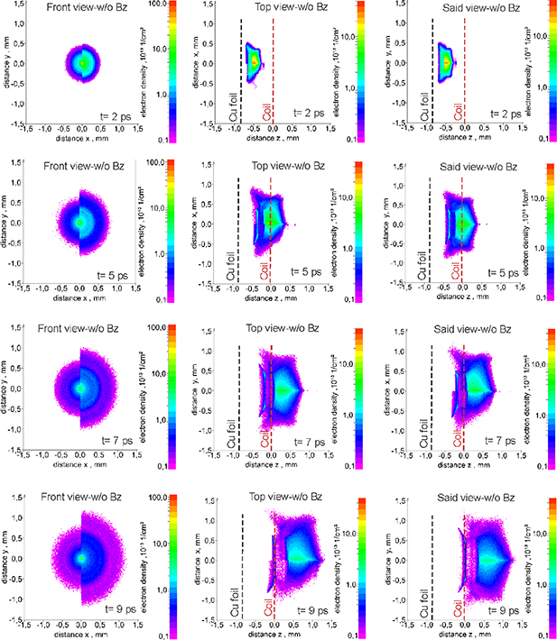
Figure 12. Density distributions of HEs in absence of the axial magnetic field obtained numerically for different expansion time: (a) front view, (b) top view and (c) side view. The asymmetry of the electron flux occurring in the distributions is related to the asymmetry observed experimentally.
Download figure:
Standard image High-resolution imageIn order to obtain information about the space-time evolution of the HE flux in the presence of a magnetic field, the distribution of the magnetic field around the coil was determined based on the measurements of the Faraday rotation angle in TGG crystal presented in III.A section taking into account its dimensions and shape. The field distribution calculated using the Biot-Savart relation is shown in figures 13(a) and (b). The energy spectra of HEs for the case with a magnetic field are shown in figure 13(c).

Figure 13. Dimension (a) and the magnetic field distribution around the coil (b) used in 3D simulations of the HE flux and the electron energy spectra for the case with presence the magnetic field obtain from the simulations (c).
Download figure:
Standard image High-resolution imageThe electron density distributions illustrating the influence of the magnetic field on the evolution of the HE flux at different times are shown in figure 14. As follows from the figure, the magnetic field clearly collimates the electron flux in the area behind the coil. However, in front of the coil, the lower energy electrons are strongly deflected from the coil axis and even turned back towards the target. It should also be noted that the asymmetry of the electron flux is significantly smaller than in the case without magnetic field (figure 12). Such homogeneity of the electron density distributions probably results from the electron spinning around the force lines of the magnetic field.

Figure 14. Electron density distributions of HEs obtained at presence of the axial magnetic field for different expansion time: (a) front view, (b) top view and (c) side view. The asymmetry of the electron density occurring in the distributions is related to the asymmetry observed experimentally.
Download figure:
Standard image High-resolution imageThe magnetic field collimates the HE flux but also leads to an increase in the electron current density and the average electron energy in the central region (near the axis), as shown in figures 15 and 16. As results from figure 15, the maximum HE current density obtained in the presence of a magnetic field is above 1012 A m−2 for t = 9 ps, which is about two orders of magnitude higher than that in the absence of a field.

Figure 15. Electron current density distributions for different expansion times in the case of: (a) absence and (b) presence of the magnetic field.
Download figure:
Standard image High-resolution image
Figure 16. The number of HEs per solid angle (a) and their average energy (b) as a function of the angle of propagation, with and without a ma.gnetic field calculated from experimentally obtained HE energy distributions.
Download figure:
Standard image High-resolution image
The results of the calculations characterizing the total number of electrons and their mean energies as a function of the propagation angle, are presented in figure 16. Figure 16(a) shows the number of electrons per solid angle as a function of the propagation angle in the absence and presence of a magnetic field, while changes in their average energy depending on the angle in the case with and without the presence of a magnetic field are shown in figure 16(b). The increase in the energy of the electrons on the coil axis under the influence of the magnetic field visible in figure 16(b) can be explained as follows. The simulation takes into account the interaction of electrons only with a magnetic field. Therefore, during the simulation, only the directions of the electron movement change, not their total velocities and energy. Moreover, the angles of propagation of individual electrons (relative to the coil axis) can only be changed by the magnetic field components perpendicular to the coil axis (Bx, By). The increase in the average energy of electrons with propagation angles close to 0 is mainly due to the defocusing of the beam in front of the coil. This effect is caused by a deviation of the electron paths from the coil axis resulting from the action of perpendicular B-field components. Due to the perturbation of the full coil symmetry (introduced by the presence of wires connecting the coil to the ground), these components are also non-zero directly on the coil axis. Electrons with lower energies are characterized by greater sensitivity to the action of the magnetic field compared to those with higher energies, and thus their paths are prone to greater deviations, i.e. they are more deflected from the paraxial area. Consequently, there is an increase in the average energy of electrons at small angles of propagation. Moreover, in the area behind the coil, the electron flux is focused due to a change in the direction of perpendicular components of the B field with respect to the situation in front of the coil. This process contributes to the increase in the number of electrons with small angles of propagation, but it is more significant for electrons with higher energies, which causes a further increase in the average energy in the group of paraxial electrons.
The simulation carried out was aimed at examining the general influence of the magnetic field generated in the DCT on the HE flux and contained a number of simplifications, including the lack of influence of electric fields generated between electrons and ions propagating through the coil on the movement of electrons or the magnetic field induced by the electron flux. In the near future, it is planned to conduct more detailed simulations in order to estimate the impact of the simplifications made on the obtained results.
5. Conclusions
The preliminary presented evaluation of the experiments performed at the PALS facility confirmed the possibility to generate magnetic fields above 5 T with 0.5 kJ laser energy using the DCT composed of a Cu disc coupled to a SC, which is operated in the capacitor-coil target mode. A significant impact of these fields on properties of the ablative plasma and the HE emission was also demonstrated. The results of measurements carried out with the use of various diagnostics and 3D simulations proved, in particular, that the magnetic field generated in the DC system leads to the collimation of the HE flux, to an increase in temperature and average energy of the electrons, and also to a considerable increase of the HE current density.
The proposed tested DCTs have a great potential to be used in a research directed to the production of magnetized plasma fluxes for various applications. In particular, they could be used in studies of the magnetized fusion target implosion where a control of the HE flux parameters plays a key role for achieving the fusion ignition. In this aspect, studies of CD targets irradiated by 3ω beam of the iodine PALS laser, i.e. at the wavelength similar to that of the LMJ and National Ignition Facility (NIF) lasers currently used for ICF research, are of particular interest.
Acknowledgments
This scientific paper has been published as a part of the international project co-financed by the Polish Ministry of Science and Higher Education within the programme called 'PMW' for 2022. This research was supported by the Access to the PALS RI under the EU LASERLAB AISBL (Grant Agreement No. 871124) project; by the Ministry of Youth and Sports of the Czech Republic (Project Nos. LM2015083 and LM2018114 (PALS RI), LTT17015, EF16_013/0001552) and by the Czech Science Foundation (Grant No. 19-24619S). This work has been carried out within the framework of the EUROfusion Consortium, funded by the European Union via the Euratom Research and Training Programme (Grant Agreement No 101052200—EUROfusion). Views and opinions expressed are however those of the author(s) only and do not necessarily reflect those of the European Union or the European Commission. Neither the European Union nor the European Commission can be held responsible for them.
Data availability statement
The data that support the findings of this study are available upon reasonable request from the authors.
The authors dedicate
This paper to memory of dr Miroslav Pfeifer, who was a great electronics specialist and with his knowledge and commitment he supported research conducted at PALS as part of research projects carried out in scientific cooperation by international research teams. This concerns in particular to the contribution to the implementation of last common studies presented in this paper, for which all the co-authors thank him.