

Abstract
Improving parameters of laser-driven proton and ion beams becomes one of the most important goals in the field of laser acceleration in order to fulfill requirements of foreseen applications. This work presents parametric 2D and 3D particle-in-cell simulations of various target designs in order to reduce proton beam divergence without significant drop in maximum energies or in proton number. The optimal target design proved to be a channel-like target which produces not only a long-lasting focusing transverse electric field in contrast to a flat foil, but also a magnetic quadrupole with strong octupole component inside the guiding channel. A combination of both electric and magnetic features results in a strong proton beam divergence reduction, accompanied by a higher uniformity of the beam, which is studied as a function of proton energy.
Export citation and abstract BibTeX RIS
1. Introduction
The increasing interest in laser-acceleration technique has been pushing the efforts made in studying and manufacturing micro/nano-structured targets forward in order to improve ion beam parameters. Such improvements aim to meet the requirements of foreseen applications with wide socioeconomic impact such as laser-driven hadrontherapy, 'fast ignition' of ICF targets, laser triggering and control of nuclear reactions, material science, chemistry (e.g. proton pulsed radiolysis), non-destructive heritage testing, etc [1, 2].
Concerning targets structuring, it was shown, both numerically and experimentally, that whereas nano-structures on the target front surface increase the maximum proton energy and enhance the number of accelerated particles significantly [3], rear-placed periodical structures affect rather angular spread of accelerated ion/proton beam [4]. In fact, ion divergence is a crucial parameter for effectiveness of the beam handling, for the transport through beamlines and often also for the fulfillment of various applications' requirements. Studies performing besides microstructures on the target back side also various materials of the target itself [5] or employing laser-excited electromagnetic pulses directed along a helical path formed by a wire attached to the target rear side [6] were already published. The post-collimation of laser-driven protons accelerated from a single flat foil was firstly demonstrated experimentally when a separated metallic cylinder (irradiated by the 2nd laser pulse) was placed as a guiding channel in the accelerated beam trajectory [7]. This clearly illustrates the promising potential of the guiding-channel geometry, even though the cylinder structure was not a part of the target and has much larger dimensions than those which have been studied in this paper. Various kinds of straight or tapering metal channels attached to or encircling a fully ionized hydrogen flat target were investigated also numerically because of their promising impact on proton beam parameters [8, 9].
The presented work introduces 2D and 3D particle-in cell (PIC) simulations of advanced target designs in order to reach as small proton divergence as possible without lowering particle number or maximum energy in a significant way. In the first part, a parametric investigation of flat and curved targets with channels of various lengths and slopes attached to their back side is compared to a reference flat foil. The second part accommodates 3D PIC simulations comparing the optimal target design chosen from 2D study with a reference flat target. In order to study the origin of changes in particle divergence related to the diverse target designs, the creation of both electric and magnetic fields is discussed. We will demonstrate that the source of ion beam focusing observed for channel-like targets is related to the establishment of focusing electric field in contrast to the flat foil case and to the creation of magnetic quadrupole with strong octupole component being well-developed and confined inside the channel. Such combined function target-magnet has focusing/defocusing planes providing additional focusing capability to the existing electric field in favorable direction and, furthermore, create a higher degree of spatial beam uniformity. In other words, individual symmetric elements of the magnetic field form a symmetric magnetic multipole which has asymmetric impact on the divergence of passing particle beam.
2. Simulations parameters
In order to adjust ion beam parameters, various designs of advanced plastic targets were performed by the use of collisionless 2D and 3D PIC code EPOCH [10], see figure 1. Different shapes consisting of both flat and curved foils with flat or tapering microstructures forming a 'channel' attached to their rear side were simulated and compared to a single flat foil. In 3D, a cylindrical geometry of the channel (i.e. the channel transverse cut is a circle) instead of a block one (i.e. the channel transverse cut would be a square) was chosen because of high-level of symmetry. The thickness both of the target itself (the part perpendicular to the laser pulse) and of the structures is set to 1 µm and the distance between the channel arms is 7 µm, which corresponds to the target lateral dimension of 9 µm. The thickness was chosen with respect to well-manufacturable limits of mylar targets already used in experiments [3] and in order to be relevant for widely used TNSA mechanism of laser-driven ion acceleration [1]. Transverse target dimensions were chosen in agreement with actual experimental conditions in terms of fitting the laser focal spot size between the rear-placed structures and in terms of reasonable limits of laser pointing stability. As a result, the target width is three times larger than the size of the laser focus having 3 µm [11, 12] which is close to optimal laser beam width in order to reach the highest laser-driven ion acceleration efficiency [13].

Figure 1. Simulated plastic targets: (a) flat target, (b) flat target with tapering 6 µm long arms forming a hole between them being 1 or 3 µm wide; (c) curved target with straight arms forming 6 µm channel of two types—firstly measured from the target rear side, i.e. from the rear side of the curved part, secondly measured from the beginning of the straight part only; (d) flat target with a straight channel having various lengths: 4, 6 or 8 µm; all targets were simulated by 2D PIC code EPOCH. The single flat foil and the flat target with 6 µm channel having cylindrical shape were simulated in 3D PIC as well—case (e) and (f), respectively.
Download figure:
Standard image High-resolution imageThe straight channels vary in lengths between 4 µm, 6 µm and 8 µm. The rising channel length is studied in order to demonstrate a proper formation of generated quasistatic EM fields, to establish a higher field integral and also in order to reach more optimal ratio between transverse and longitudinal dimensions widely used when designing magnets [14–16]. All mentioned aspects will be discussed further in following sections. In the case of the flat target with tapering channel, the arms length is set to 6 µm while the dimension of the hole between these arms is changed as depicted in figure 1(b) in green (i.e. the angle between the flat part and the arm varies). Curved foils have a radius of curvature of 3.5 µm (the distance between parallel arms is the same as in the case of flat foils with straight channels, i.e. 7 µm) and the length of the attached channel varies. The case of 2.5 µm straight arms represents the situation where the 6 µm channel is measured already from the rear side of the curvature, whilst the case of 6 µm arms represents the situation where only the straight part is considered to be a 'channel'.
In all simulations, the full ionization of targets is assumed. Since we are using relatively light and thin/tiny plastic targets, the approximation of fully ionized dielectric material is acceptable [17] and widely used because of an efficient propagation of generated hot electrons through such thin target material [18–20]. Typically, ionization by laser pulse occurs already for values of  , which implies that the partial ionization would occur already during the rising edge of the pulse. In fact, the profile of the realistic laser pulse is complicated and it includes a pedestal of amplified spontaneous emission (ASE) as well as compressed prepulses and a so-called coherent pedestal which is the slope rising slower than an ideal Gaussian pulse [21]. The hot electrons are thus generated even before the main peak pulse comes. Generally in PIC simulations, only a limited part of the laser pulse (usually assumed to have an optimal shape) is simulated, which supports the approximation of fully ionized targets used here.
All simulations were performed with a linearly polarized laser pulse (the polarization plane corresponds to the simulation area in 2D) having the wavelength λ = 800 nm and intensity I = 5 × 10²¹ W cm−2 which corresponds to dimensionless laser amplitude of a0 = 48. The laser beam has the focal spot size of 3 µm (FWHM) and propagates along the x-axis in the positive direction, i.e. has 0∘ angle of incidence on the target. The spatial profile of the laser pulse is Gaussian, whilst the time profile has sin2 shape in intensity both in 2D and 3D. The full duration of the pulse is 60 fs which approximately corresponds to 30 fs at FWHM for a Gaussian profile. The used laser parameters are in good agreement with the L3 HAPLS laser at ELI-Beamlines [22], which is the 1 PW laser system with high repetition rate capability (up to 10 Hz), which will be available at the ELIMAIA beamline dedicated to various user experiments [11]. Both 2D and 3D simulations were run for additional 270 fs after the beginning of the laser–target interaction and the simulation area has dimensions of 50 µm × 30 µm (one cell was a square having the edge of 8 nm) in 2D and of 32.0 µm × 13.2 µm × 13.2 µm (one cell was a cube with the edge of 16 nm) in 3D. Targets are made of plastic having density 200 nc . Three particle species are used in the simulation (electrons, protons and carbon ions C6 + ), while quasineutrality stays conserved.
3. Investigation of various target designs
Various target designs were primarily proposed in order to improve particle beam parameters, mainly angular characteristics of the accelerated proton beam. Half-angle divergence was measured at FWHM at the end of both 2D and 3D simulations, i.e. at 270 fs after the start of laser–target interaction. All presented target designs were simulated primarily in 2D geometry and only protons moving forward in ±3.5 µm cut or in ±0.5 µm cut around the laser propagation axis were analyzed, see results in table 1. The first space interval corresponds to the inner diameter of the channel(s) and it was used in order to analyze mainly the protons accelerated from the channel along the laser propagation axis. The half-angle proton divergence was reduced in comparison to the flat foil by 34% in the case of the flat target with 8 µm long channel, which is the strongest decrease from all targets being studied in 2D within this work. In fact, divergence was reduced by 29% and by 2% for the flat target with 6 µm and 4 µm long channel, respectively.
Table 1. Summary of reached proton beam parameters (divergence and energy) from both 2D and 3D simulations obtained at the end of the each simulation. Two-dimensional study includes all simulated flat foil (FF) and curved foil (CF) target types (according to figure 1), in 3D only the optimal target design and the flat foil (as a reference) were simulated.
| Half-angle divergence a (∘) |
 (MeV) (MeV) | ||||||||
|---|---|---|---|---|---|---|---|---|---|
| 2D b | 3D c | ||||||||
| Target type | ±3.5 µm | ±0.5 µm | Interval | x–y | x–z | 2D | 3D | ||
| Flat foil (=FF) | 11.2 | 100% | 4.6 | 100% | > 0.5 MeV | 15.4 | 17.7 | 108 | 62 |
| > 10 MeV | 10.3 | 12.4 | |||||||
| > 30 MeV | 9.3 | 9.8 | |||||||
| FF with straight 4 µm channel | 11.0 | 98% | 2.5 | 54% | — | 97 | — | ||
| FF with straight 6 µm channel | 8.0 | 71% | 1.8 | 39% | > 0.5 MeV | 6.8 | 8.6 | 96 | 56 |
| > 10 MeV | 3.1 | 5.5 | |||||||
| > 30 MeV | 3.0 | 7.2 | |||||||
| FF with straight 8 µm channel | 7.4 | 66% | 1.5 | 33% | — | 88 | — | ||
| FF with tapering channel (1 µm hole) | 18.1 | 162% | 4.6 | 100% | — | 78 | — | ||
| FF with tapering channel (3 µm hole) | 12.6 | 113% | 2.8 | 61% | — | 94 | — | ||
| CF with straight 6 µm channel | 14.8 | 132% | 3.3 | 72% | — | 92 | — | ||
| CF with straight 2.5 µm channel | 20.0 | 179% | 3.7 | 80% | — | 103 | — | ||
a Half-angle proton divergence measured at FWHM; only protons which are moving forward (px > 0) were analyzed. b In 2D, only protons within the specified space cut around the laser propagation axis and with energy above 0.5 MeV were analyzed. The percentage reduction of the divergence in comparison to the flat foil is given. c In 3D, only protons inside the cylinder of radius 3.5 µm around the laser propagation axis (i.e. the channel inner dimension) and exceeding various energy thresholds were analyzed; two divergence planes are investigated.
The second presented 2D space cut in table 1 (i.e. ±0.5 µm around the laser propagation axis) was done in order to analyze the narrow on-axis-proton beam only (visible in figure 3(b)) and in order to investigate if the targets ability to modify the proton divergence strongly depends on the space interval being analyzed. This analysis shows even stronger divergence reduction—namely by 61% for the flat target with 6 µm channel in comparison to the flat foil. Nevertheless, in spite of diverse nominal values, flat targets with channels show a clear ability to decrease the proton divergence. Moreover, the dependence on the channel length was clearly demonstrated independently from the space cut used.
Although the longer channel proved to provide a better focusing capability because of the higher electric field integral (which quantifies the total field strength produced), the effectiveness of decreasing the particle divergence does not increase linearly with the extension of the channel length. In fact, this effectiveness would be developed to its full potential (and it does not rise much more) for a specific value, see table 1. Moreover, the length of the arms has natural limits regarding a fabrication of such targets which has to be taken into account (i.e. the arms cannot be too long and too thin to ensure the mechanical stability of the channel).
In 3D, the angular proton distributions were analyzed only within the cylinder having radius of 3.5 µm around the laser propagation axis but for various energy intervals—namely for protons above 0.5 MeV, above 10 MeV and above 30 MeV. From the results presented in table 1 and in figure 2, showing the 3D comparison of proton beam divergence between the flat and the 6 µm long channel targets, it is clearly observable that protons are focused slightly better in x–y than in x–z plane. This feature does not change with time, only the focusing efficiency varies with the energy interval. Furthermore, it corresponds well to the slightly z-elongated shape of the proton beam cross section already visible in the middle of the channel, see figure 3(a). The dependence of half-angle divergence reduction on proton energy will be discussed in section 5, where the analysis of electric and magnetic field effectiveness in various energy intervals is presented. The reason of different focusing efficiency in various planes is bounded with the establishment of magnetic multipoles inside the channel and it will be discussed in section 4.2.

Figure 2. Comparison of proton angular distributions in x–y and x–z planes between the flat target and the flat target with 6 µm long channel at the end of 3D simulations. Only protons moving forward (px>0) within the cylinder of radius 3.5 µm (i.e. the channel inner dimension) and having energy (a) above 0.5 MeV, (b) above 10 MeV or (c) above 30 MeV were taken for the analysis.
Download figure:
Standard image High-resolution image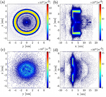
Figure 3. Comparison of proton density plots and angular distributions between the flat foil and the channel target, 3D simulations. Proton density plots are shown in y–z plane at 3 µm behind the flat rear side of both (a) the channel target (i.e. in the middle of the channel length) and (c) the flat target at 180 fs after the start of laser–target interaction. Proton density plots (b) and (d) are shown in x–y plane for the channel and the flat target, respectively, at the end of the simulation, i.e. at 270 fs after the start of laser–target interaction.
Download figure:
Standard image High-resolution imageFrom 2D parametric study, a clear tendency towards maximum proton energy reduction in the case of targets with straight channels is observed, see table 1. This phenomenon is stronger with longer guiding arms, because the maximum proton energy depends on the strength of the accelerating sheath field Ex
, which varies with the target design. Nevertheless, the difference between the field magnitudes is not very large, as well as the energy drop. Numerically, the proton energy was reduced in comparison to the flat foil by 19% and by 12% in the case of 8 µm and of 6 µm long arms. Consequently, the optimal target design, from the point of view of a significant divergence decrease accompanied by a small drop in maximum energies and a conservation of proton number, is the flat target with 6 µm straight channel. Actually, the proton numbers, i.e. precisely the ratios between the number of forwardly accelerated protons above 10 MeV and above 0.5 MeV in 2D, were similar in the case of the channel target of any length compared to the flat foil. In 3D, the energy drop was weaker—only 10% in comparison to the flat foil, i.e. energies decreases from  MeV to
  MeV. The energy reduction between 3D and 2D was slightly above 40% for both target designs. The difference between maximum proton energy observed in 2D and 3D simulations is caused by the fact that electrons can spread in y- and z-directions in the case of 3D simulation in contrast to 2D where only one direction is possible. This results in a lower electron density and temperature in the 3D case, which then leads to a weaker proton acceleration compared to the 1D and 2D cases [23–25].
Eventually, we would like to briefly comment the results of other target designs studied in 2D. Firstly, it was investigated that flat foils with tapering channel can conceptually act as a collimator. In a nutshell, tapering arms provide electrostatic field which is strong enough to catch the protons with low energy and high divergence. In other words, this channel is able to 'cut' the particle beam accelerated from the target flat part and thus to select the maximum divergence angle being accepted (i.e. it cuts the low energy part of the beam). For example, the target with a 3 µm wide hole between its tapering arms can reduce the number of protons having 0–5 MeV by 49%, whilst the target with a 1 µm wide hole by 58%. Since the less energetic protons have bigger divergence [26, 27], the energy interval of the stopped ones naturally depends on the size of the hole, i.e. a smaller hole stops more energetic particles.
The growth of proton divergence associated with curved channel targets is caused by the TNSA mechanism [28], i.e. by the fact that ions are accelerated perpendicularly to the target rear surface. Consequently, protons are focused into a small area corresponding to the geometrical center of the curvature. Unfortunately, the focusing field is not strong enough to sustain the particles in a narrow beam when they reach the geometrical center. Consequently, the beam is defocused again in a short time behind the center of the target curvature (located at 3.5 µm behind the target back side in the laser propagation direction), because particles follow their original trajectory. This feature is suppressed with the longer straight channel attached to the curved part, see table 1, because of the bigger electric field integral, i.e. stronger particle focusing since the field acts over a longer distance.
4. Establishment of electromagnetic fields and their role in modification of proton divergence
The principle of the decreasing divergence phenomenon in the case of the channel target in comparison to the flat foil stems from the combination of two things: (a) the change in transverse Ey field in the case of the channel target due to different hot electrons motion (Ey and Ez in 3D) and (b) the formation of multipole magnetic field.
4.1. Focusing by the transverse electric field
The origin of the focusing phenomenon in the case of targets with channel is connected to the establishment of transverse electric fields. Whereas in the case of the channel target the transverse electric field components (Ey and Ez ) are positive for negative transverse positions (y and z, respectively) and vice versa, in the case of the flat foil the situation is radically changed to opposite orientation after a few tens of fs after the laser–target interaction. In other words, electric force components affecting divergence are established in focusing direction for both foils at the very beginning, but the field orientation lasts during the whole simulation (i.e. ∼ 270 fs) only in the case of the channel target. Contrary, in the case of the flat foil the focusing field is attenuated quickly (i.e. ∼ 20 fs) and it is switched to the defocusing orientation, see figure 4. The forces push positively charged particles produced from the flat target away from the laser axis which increases proton beam divergence.
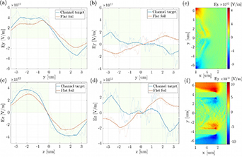
Figure 4. Demonstration of the opposite orientation establishment of electric field components affecting particle divergence. Transverse electric field components Ey and Ez are plotted along their corresponding axis for the flat foil (red curve) and the flat foil with 6 µm channel (blue curve) at 30 fs ((a), (c)) and at 90 fs ((b), (d)) after the start of laser–target interaction. Focusing regions for ions are highlighted in green, defocusing regions in white. The analysis was done 3 µm behind the rear side of the flat part of the both foils, i.e. in the middle of the channel length in the case of the target with guiding arms. Graphs (e) and (f) show transverse electric field Ey in the plane x–y at 90 fs after the start of laser–target interaction for the flat foil and the channel target, respectively.
Download figure:
Standard image High-resolution imageSuch big difference in electric field formation is caused by the target shape and by the corresponding spatial density and the movement of hot electrons in the region where protons are accelerated. In the case of the flat foil without any additional structure, hot electrons escape the target at its rear side, which temporarily leads to the focusing electric field formation (figures 4(a) and (c)), since the area, where the ions are accelerated, is filled with negative electrons. Nevertheless, such electrons are spread to the sides quickly (few tens of femtoseconds), which results in uncompensated transverse density gradient of the accelerated ions bounded with the establishment of transverse electric field with opposite, i.e. defocusing, direction as visible in figures 4(b) and (d).
In the case of the flat foil with channel, the situation is different. Firstly, electrons are accelerated from the flat part of the target, however in contrast to the flat foil, they are confined by the channel afterwards. In particular, they do not spread to the sides, but propagate along the channel walls, recirculate in the target and/or bounce within the guiding cylinder walls. Originally focusing electric field is thus confined in its orientation longer in contrast to the flat foil, because electrons do not spread away from the laser axis quickly, but they stay in the vicinity of the guiding channel walls where the quasineutrality is consequently violated. Therefore these electrons are attracted back to the center which causes the presented focusing electric field. Such feature is the same for both electric fields affecting the divergence, i.e. for Ey as well as for Ez as shown in figure 4. The electrons motion inside the channel and their corresponding formation of current loops will be discussed later in the section 4.2.
The difference between electric field orientation of the flat target and the channel target is also demonstrated in figures 4(e) and (f), where Ey component is shown in side view, i.e. in x–y plane at 90 fs after the start of laser–target interaction, which corresponds to the situation depicted in figure 4(b). This is a clear demonstration of the efficient divergence reduction in the case of flat targets with straight channels.
4.2. Influence of multipole magnetic field
Strong magnetic fields driven by nonparallel gradients of electron temperature and density are generated at the back side of a target flat-part (i.e. the part perpendicular to the laser beam axis direction) by radial thermal transport mechanism as described in [29, 30], and experimentally seen in [31]. In fact, the orientation of transverse magnetic fields schematically depicted in figure 5(a) corresponds to the laser-generated hot electron transport along channel arms forming loops from the return current. The situation is demonstrated by plots showing current densities in the laser axis direction for both target designs, see figures 5(b) and (c). In the case of the channel target, electron forward and return flows are visible along the arms, whereas in the case of the flat foil, electrons do not undergo any preferable motion.
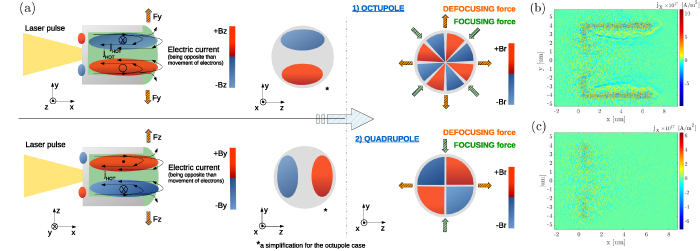
Figure 5. (a) Schematic sketch of the establishment of magnetic field components driven by electron motion, i.e. by the formation of current loops, and of the magnetic multipoles creation in all planes of Cartesian coordinate system. Both magnetic octupole and quadrupole were observed inside the channel, depending on the time and the position along the channel length. Electron current density jx showing prevailing electron motion in the laser axis direction for (b) the channel target and for (c) the flat foil is presented at the end of 2D simulations.
Download figure:
Standard image High-resolution imageConsequently, well-organized magnetic field structure inside the guiding channel is expected and will be proved. From a divergence point of view, both By
magnetic field (in x–z plane) and Bz
field (in x–y plane) have defocusing effect on a proton beam passing through the cylinder. Nevertheless, if these symmetric magnetic fields are combined together into the radial one  (where r represents the radius measured from the channel center), a quadrupole as well as an octupole magnetic fields are obtained. The order of prevailing multipole depends on the time and the exact position along the channel, see figures 6(g) and (h), where both eight- and four-pole multipoles are visible, respectively.

Figure 6. Magnetic field comparison; 2D case: magnetic field component Bz for various target types at the end of the simulation: (a) the flat foil; (b) the flat target with straight 6 µm long channel; (c) the curved foil with straight 6 µm long channel. 3D case: Magnetic field components Br and Bz in various 2D planes of (d)–(f) the flat foil and of (g)–(i) the channel target (i.e. the case corresponding to (b) in 2D). Radial magnetic field Br in y–z plane is taken at 160 fs after the start of laser–target interaction (d) + (g) at 3 µm (the channel case (g) shows the octupole (i.e. the quadrupole with strong octupole component)) and (e) + (h) at 5.85 µm (the channel case (h) shows the quadrupole) behind the rear side of the flat target parts. At the presented time scan, the acceleration process is fully developed and a majority of protons are still in the channel. (f) + (i) show Bz field at the end of the simulations.
Download figure:
Standard image High-resolution image4.2.1. Quadrupole field with strong octupole component.
The combination of quadrupole and octupole magnetic fields is natural, since an octupole is the first and the strongest not allowed high order harmonics of a quadrupole [16, 32]. Actually, the so-called not allowed harmonics become present when the magnet symmetry is somehow violated, which is exactly the case of disintegrated target by the laser pulse. Contrary, allowed harmonics are always present in real multipoles and can be only suppressed but not removed.
In fact, octupole magnets are usually used in combination with quadrupoles for correction of spherical aberrations in accelerator physics [33] and they make particle beam spatially uniform [34]. As depicted in figure 5(a), if a simple analysis of magnetic Lorentz force is made for an octupole, we can see defocusing forces along the Cartesian coordinate system and focusing forces along the axes rotated by 45∘. The space differences between these forces are small and uniformity of the produced particle beam is achieved (which can be justified from the beam optics formulation for an octupole [14]) instead of setting any preferable focusing or defocusing transverse directions. Contrary, quadrupoles are usually used for focusing particles in one plane only, because in the second plane they cause defocusing [14, 15]. The position of positive and negative poles determines their focusing and defocusing plane(s), see figure 5(a). This means that a perfect quadrupolar symmetric field (which arose from symmetric magnetic field components) will produce an asymmetric particle beam. Since this effect is widely known in accelerator physics, two quadrupoles are usually used in a so-called FODO cell, to have a net focusing effect, and three quadrupoles to have both vertical and horizontal focal points in the same position [14, 15]. Both divergence reduction in preferable plane and higher spatial uniformity of accelerated proton beam from the channel target were observed in our simulations.
Generally, any real magnetic or electrostatic lens, which is a good approximation of our channel target, suffers from geometrical aberration and from chromatic aberration (which is here strong due to the large energy spread). Whereas the various focusing in different planes is caused by magnetic quadrupole, the minor decentralization of some angular distributions is caused by the combination of non-ideally homogeneous particle beam, non-ideal hot electron transport and the field imperfections, see figure 2. All these features are contained also in accelerator beamlines [14, 15].
4.2.2. Strength of generated multipole and its time&space evolution.
Produced multipole magnetic field inside the guiding channel has a strong gradient, namely 5.7 kT µm−1 (i.e. 5.7 GT m−1 over 7 µm (the total length of the channel target)) in the case of both Bz field along y-axis and By field along z-axis. This corresponds to a relatively high field integral of 0.368 T·m (the maximum was reached at 90 fs after the start of the interaction). The values of the field integral vary with time although they remain comparatively strong during the whole simulation. Specifically, the magnetic field integral starts at the value of 0.217 T·m at the beginning of the ion acceleration, whereas it drops down from the maximum of 0.368 T·m to 0.098 T·m at the end of the simulation. For comparison, real quadrupole electromagnets used for the ion beam focusing at experimental beamlines have, e.g. gradients up to 10 T m−1 over 70 mm (the field integral 0.084 T·m); PMQ magnets have, e.g. 100 T m−1 over 36 mm (the field integral 0.291 T·m), [11, 35]. The field integral value gives a proper insight and a comparison of the magnetic field effectiveness for different magnetic lenses, since it is reflecting both the field strength and the distance at which it affects the particles directly. On the other hand, strong fluctuations were observed in By –y and Bz –z characteristics, which should be zero in ideal quadrupoles or octupoles. The amplitude of these fluctuations reaches at maximum 25% of By (along z-axis) and of Bz (along y-axis) field amplitudes, whilst in real quadrupole/octupole well-designed magnets it is a few tenths of percent. These oscillations are caused by the combination of the additionally generated fields by the moving particles, which are not present in standard magnets, and by a limited number of numerical macroparticles in computationally demanding 3D simulation(s). Nevertheless, a quadrupole/octupole structure of the field is definitely present.
Multipole magnetic field has different strength (gradient) from the central axis to the channel walls because of various density of current loops. Moreover, if we took the channel target as a magnet, the field would not be established properly because of insufficient target's (magnet's) dimensions. In fact, the magnet mechanical length should be at least two times longer than its diameter in order to let the magnetic field develop to its full power [14]. The radial magnetic field varies also along the channel length and with time, because the quadrupole has the strong octupole error (as discussed in section 4.2.1). Despite of that, the magnetic multipole remains relatively strong inside the channel during the whole acceleration process (few hundreds of femtoseconds), it has relatively well-defined shape and high field integral in contrast to the flat foil. In fact, in the case of the reference flat target, magnetic field components drop in amplitudes quickly (in 10 fs after the end of laser–target interaction) and the field spreads to the sides, which, in later times, results in a creation of only a week magnetic multipole with no specific order and low field integral, see figures 6(d) and (e). The difference between these two scenarios lies in already discussed organized or disorganized electron motion (see figures 5(b) and (c)) and in spatial confinement of the field structure. To summarize, although the general magnetic multipole creation was seen in both target cases, it was formed and confined well only for the channel one.
4.2.3. Comparison between 2D and 3D.
The magnetic field amplitude was suppressed in 3D for each target case compared to 2D, similarly as the electric field amplitude was, since the magnetic field is generated by the current loops of electrons. With an extra added dimension, electrons can expand in two transverse axes, not only in one, which limits their current in each direction over the same distance. Magnetic field amplitude is then reduced accordingly. Nevertheless, the orientation of transverse magnetic field is not affected by the target design as it is in the case of transverse electric field. Higher values of magnetic field were observed in 2D for all structured targets in comparison to the flat foil, see figure 6.
4.2.4. Summary.
A quadrupolar magnetic field with strong octupole component was observed in our 3D simulation of the channel target. Two effects on passing particle beam can be observed. Firstly, the formation of quadrupole magnetic field contributes to the establishment of the preferable focusing plane x–y (as discussed earlier, see figure 2 and table 1). Secondly, octupole field makes the beam more uniform, as visible also in the comparison of beam cross sections for various 3D simulated targets in figures 3(a) and (c).
5. Comparison of the effect of magnetic and electric field
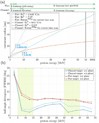
In fact, the ability of divergence modification can be assigned both to electric and to magnetic fields as already demonstrated, although their effectiveness depends on the proton energy. In figure 7(a) the comparison of electric and magnetic curvature radiuses in x–y plane (taken from the electric and the magnetic rigidity) of a reference proton having particular energy are shown for the flat and the channel target simulated in 3D. The reference proton moves only along the x-axis and the values of magnetic and of electric fields were taken as an average from 3D PIC simulation at its end for both targets. In other words, the graph shows how strongly a trajectory of the reference proton (moving along the laser axis with particular energy) would be affected by EM fields (3D PIC simulated values) when the particle propagates through. Even though the amplitudes of both fields fluctuate in time during the simulation, the average values are sufficiently stable. It was verified that the proton energy value, dividing the areas where electric and magnetic fields become more efficient, does not change substantially (i.e. quantitatively by a few mega electronvolts on the overall scale of tens mega electronvolts). In general, this analysis provides only an approximate information, because the assumption of a reference proton propagating only along the laser axis was used. In reality, particles move with a non-zero momentum also in the y- and z-directions. Consequently, the energetic boundary between electric and magnetic field effectiveness will vary, but the tendency remains the same.
Figure 7. Comparison of electric and of magnetic field impact on the proton beam divergence for the channel and the flat target at the end of 3D simulations: (a) the dependence of electric and magnetic curvature radius in x−y plane (taken from electric and magnetic rigidity) on a particular energy of the reference proton (moving along x-axis); the nature of the radius (de/focusing) is shown above the graph for both fields; (b) half-angle proton beam divergence (FWHM) in both x–y and x–z planes inferred from 3D PIC simulations and analyzed separately for energy intervals of 5 MeV width up to 55 MeV.
Download figure:
Standard image High-resolution image
One can notice that the electric field affects the low energetic particles more than those with high energies in both target cases (i.e. the radius of curvature (the bending of the particle trajectory) is smaller for the low energy particles). Nevertheless, this fact alone gives no information whether the effect is focusing or defocusing, which is why the additional knowledge of the bending direction is crucial. Therefore, the green legend was added at the top of figure 7(a) in order to highlight that the electric field causes a focusing effect on protons in the case of the channel target, whereas it generates defocusing effect in the case of the flat foil (see also the section 4.1 and figure 4). The proton beam parameters, including not only the divergence but also the uniformity of the beam, are mostly affected by magnetic fields for proton energies above 3.5 MeV and above 8.5 MeV for the flat and the channel target, respectively. In contrast to the electric field, the magnetic field is well-defined for the channel target only and it is disorganized for the flat one. Thus, the magnetic multipole is focusing (quadrupole) in y-direction and/or makes the beam more uniform (octupole) in the case of the channel target, but it has no specific order in the case of the flat foil, i.e. no specific effect on protons.
The effect of the electric and the magnetic fields is depicted in figure 7(b) where the values of half-angle divergence (FWHM) in x–y plane (studied in figure 7(a)) as well as in x–z plane are shown for the flat and the channel target with dependence on proton energy. Here, the proton divergence values are taken at the end of 3D PIC simulations, i.e. no reference proton strictly moving only in x-direction was used as in the case of figure 7(a). Consequently, this analysis indirectly covers various field conditions (e.g. various orders of the magnetic multipoles and various field strengths along and across the whole channel), because the resulting proton divergences were affected by them. In reality it means that, whereas, e.g. the 40 MeV protons experienced the quadrupole field in the middle of the channel, the 20 MeV protons did not, because the order of the multipole had been already changed when they arrived to that place. This is the difference from figure 7(a) which is more static in this meaning and it serves as a model situation.
The energy intervals analyzed in figure 7(b) were sampled from 0 MeV to 55 MeV with the width of 5 MeV. Although the maximum energies were slightly higher than 55 MeV (56 MeV and 62 MeV for the channel and the flat target, respectively), the statistics was low in these intervals, thus they are not included in the analysis. The results indicating a reduction in ion beam divergence by magnetic field depend on specific particle energy and they are in good agreement with the fact that a quadrupole and an octupole act as a chromatic lens [14]. We can clearly observe two regions of proton divergence reduction in the case of the channel target in comparison to the flat one (marked in green, being stronger in y-direction).
The first region is located approximately in the energy interval of  MeV and is caused by the combination of focusing electric field and well-defined magnetic field in the case of the channel target where both terms have significantly lower curvature radius (in figure 7(a)) than those for the flat foil. Moreover, in the case of the flat foil, the electric field has defocusing effect and the magnetic field does not form a proper multipole as discussed earlier, thus it has no specific effect on protons. The divergence of protons moving inside a cylinder with radius of 3.5 µm was reduced in this energy interval by 78% and by 69% for x–y and x–z planes in comparison to the flat foil, respectively (the overall divergence drop of protons above 0.5 MeV was 56% and 51% for various planes, see table 1 and figure 2).
The second region, where the proton divergence was effectively reduced, is located in the energy interval of  MeV and is caused by the favorable establishment of the magnetic quadrupole focusing in the y-direction and appearing at the position where the protons of corresponding energy were located at that time. In this case, the divergence of protons moving inside a cylinder with radius of 3.5 µm was reduced by 73% and by 46% in x–y and x–z planes in comparison to the flat foil, respectively (the overall divergence drop of protons above 30 MeV was 68% and 27% for various planes, see table 1 and figure 2).
Naturally, the difference between divergence values in various planes is greater in the channel target case than in the case of the flat foil where both planes show more similar results since no proper quadrupole was formed. Nevertheless, a moderate drop with respect to the flat foil was recorded in x–z quadrupole defocusing plane as well because the focusing electric field was still present. It is actually the reason why the difference between the channel target planes are bigger in the high-energy interval, where the electric field is less efficient, than in the low-energy interval.
6. Discussion: towards future experiments
Although the parametric study on laser parameters is above the scope of this work, some tendencies can be predicted. For instance, if significantly higher laser intensity had been used, the bigger thickness of target plastic material would be needed to avoid full penetration of the laser pulse through the foil. If the laser pulse penetrates the target completely, different accelerating mechanisms as well as diverse establishment of EM fields are expected. The main changes will be connected to breaking the symmetry, decomposing the target and corresponding change in the movement of hot electrons. Contrarily, if lower laser intensity had been used, lower energy of protons and weaker EM fields due to lower temperature of electrons would be expected.
Besides laser parameters, both material and dimensions of the target itself can be discussed. If the radius of the cylinder would be larger, but the channel length stays unchanged, the EM fields, mainly the magnetic multipole, would be worse confined because of a larger area where hot electrons can be spread. It would rise the difference in the field amplitude between the channel center and along the channel walls which results in less homogeneous EM field-effect on the accelerated particle beam. On the other hand, with longer channel arms and the same cylinder inner radius (which seems to be harder to manufacture), we expect a higher beam collimation because of the higher field integral (i.e. the longer path in the well-defined EM field for particles) and the more optimal ratio between the transverse and the longitudinal dimension of the self-produced target-magnet discussed earlier.
In previous works performing channel-like targets, usually two materials were used—a light low-Z material for the target part placed perpendicularly to the laser pulse, and a high-Z material for cylinder/arms/structures [8, 9]. The possible technologies able to fabricate variously structured targets include, for example, focused ion beam (FIB) technique. The FIB can produce targets having the thicknesses down to several tens of nm with lateral dimensions up to ones of centimeter [36]. Furthermore, the free-standing SiN membranes (hundreds of nanometers) have been already deposited by a plasma enhanced chemical vapor deposition (PECVD) reactor on a silicon substrate and then lithographically shaped into various gratings and structures by a chemical etching [4, 37]. This indicates possible ways how the suggested channel target design may be produced.
In principle, the single plastic channel target might be also 3D printed as a whole by advanced technologies, which are able to provide sub-micrometer scales resolutions and have been extended to polymer materials lately [38, 39]. The single target is then suitable to be attached to the supporting foil having an aperture, similarly as in [21]. Such target arrangement can be placed repeatedly in the target tower [11], which is be able to switch the targets even at relatively high repetition rates enabled by ultrashort-pulsed laser systems.
Naturally, the possibility of cryogenic or crystal targets, which can be even lighter than widely used plastic and thus can provide higher energy protons, can be questioned. Generally, forming a precise shape described in this paper is a nontrivial task for cryogenic engineering, although the cylindrical column, planar jets, hydrogen cryogenic ribbons or single-framed cryogenic targets have been already produced [40–45].
Each target material brings different advantages (e.g. higher energy of protons, suitability for high repetition rates experiments, vacuum compatibility, pure materials, debris free interaction) and suffers from various difficulties (e.g. hard possibility of shaping, handling and stabilizing, extra equipment present in a vacuum chamber). Plastic targets used in our simulations provide the accelerated proton beam of satisfactory parameters in return for sufficient balance between the vacuum compatibility, material availability and target handling and stability (which is important, e.g. for positioning of the laser focus on a target front surface).
7. Summary and conclusions
In order to improve laser-driven proton beam parameters, a set of 2D PIC simulations performing various target designs including flat or curved foils with straight or tapering channels attached to their rear side was compared to the flat foil as reference. The flat channel target with a few microns long straight arms was found in this 2D study as an optimal target design which is the reason why it was investigated in 3D as well.
Crucial differences between both the electric and the magnetic fields formation, their confinement and orientation were observed in 3D PIC simulations for the cylindrical channel target in comparison to the flat one. The long-lasting electric focusing field confined by the guiding cylinder was shown in contrast to mostly defocusing field of the reference flat foil. Furthermore, the creation of a magnetic quadrupole with extremely strong octupole component inside the cylindrical channel was described through the combination of well-confined transverse magnetic fields. These fields were established by the electron motion along the guiding arms and their formation of current loops. Contrarily, in the case of the flat target, no exact order magnetic multipole was established because electrons did not have any preferable flow and did not form desired current loops. In fact, the phenomenon of magnetic multipole formed inside channel targets was described for the first time according to our knowledge, which opens new possibilities in shaping particle beams magnetically already during the acceleration process by using ad-hoc designed targets.
To conclude, the presented work demonstrates the ability of straight channel targets to decrease proton beam divergence accompanied by no significant drop in proton number, negligible reduction of maximum proton energy and improved uniformity of the beam.
Acknowledgments
This work has been supported by the project Advanced research using high intensity laser produced photons and particles (CZ.02.1.01/0.0/0.0/16_019/0000789) from European Regional Development Fund (ADONIS), by the project LQ1606 with the financial support of the Ministry of Education, Youth and Sports as the part of targeted support from the National Programme of Sustainability II. The simulations were done by using Particle-in-cell code EPOCH being funded by the UK EPSRC Grants EP/G054950/1, EP/G056803/1, EP/G055165/1 and EP/M022463/1. Computational resources were provided by ECLIPSE cluster of ELI-Beamlines and by the IT4Innovations Centre of Excellence supported by The Ministry of Education, Youth and Sports from the Large Infrastructures for Research, Experimental Development and Innovations project 'e-Infrastructure CZ—LM2018140'. J Psikal also acknowledges the support from European Regional Development Fund—Project CAS ('Center of Advanced Applied Sciences') No. CZ.02.1.01/0.0/0.0/16_019/0000778. Fruitful discussions with T Chagovets from ELI-Beamlines are gratefully acknowledged.
Data availability statement
The data generated and/or analysed during the current study are not publicly available for legal/ethical reasons but are available from the corresponding author on reasonable request.